CN212329151U - Retractable drill pipe inner wall cleaning mechanism - Google Patents

Retractable drill pipe inner wall cleaning mechanism Download PDF

Info

Publication number
CN212329151U
CN212329151U CN202021003407.7U CN202021003407U CN212329151U CN 212329151 U CN212329151 U CN 212329151U CN 202021003407 U CN202021003407 U CN 202021003407U CN 212329151 U CN212329151 U CN 212329151U
Authority
CN
China
Prior art keywords
water pipe
drill pipe
wall
wall cleaning
pressure water
Prior art date
Legal status (The legal status is an assumption and is not a legal conclusion. Google has not performed a legal analysis and makes no representation as to the accuracy of the status listed.)
Expired - Fee Related
Application number
CN202021003407.7U
Other languages
Chinese (zh)
Inventor
夏浩
唐瑞
莫丽
Current Assignee (The listed assignees may be inaccurate. Google has not performed a legal analysis and makes no representation or warranty as to the accuracy of the list.)
Southwest Petroleum University
Original Assignee
Southwest Petroleum University
Priority date (The priority date is an assumption and is not a legal conclusion. Google has not performed a legal analysis and makes no representation as to the accuracy of the date listed.)
Filing date
Publication date
Application filed by Southwest Petroleum University filed Critical Southwest Petroleum University
Priority to CN202021003407.7U priority Critical patent/CN212329151U/en
Application granted granted Critical
Publication of CN212329151U publication Critical patent/CN212329151U/en
Expired - Fee Related legal-status Critical Current
Anticipated expiration legal-status Critical

Links

Images

Landscapes

  • Cleaning By Liquid Or Steam (AREA)

Abstract

本实用新型提供一种可收缩式钻杆内壁清洗机构,主要由内壁清洗部分、驱动部分、水管缠绕部分组成;其中内壁清洗部分高压喷头通过刚性高压水管与软性高压水管连接;驱动部分和水管缠绕部分通过电机、齿轮、摩擦轮、滚筒、皮带及皮带轮在清洗时将内壁清洗部分匀速推出,进入钻杆后,喷头释放出高压水流即可实现对钻杆内壁的清洗,同时从喷头喷出的侧向水流还可为内壁清洗部分提供向前的力使喷头顺利沿着内壁移动,清洗完毕后再收回;该实用新型主要应用于钻杆清洗的流水线上,主要优势在于,该机构结构简单能大大减少市面上钻杆内壁清洗装置的占地面积,还可实现对整个钻杆内壁的清洗,提高清洗质量及效率,增加钻杆使用寿命。

Figure 202021003407

The utility model provides a retractable drill pipe inner wall cleaning mechanism, which is mainly composed of an inner wall cleaning part, a driving part and a water pipe winding part; the high pressure nozzle of the inner wall cleaning part is connected with a soft high pressure water pipe through a rigid high pressure water pipe; the driving part and the water pipe The winding part pushes out the cleaning part of the inner wall at a constant speed through the motor, gear, friction wheel, roller, belt and pulley during cleaning. After entering the drill pipe, the nozzle releases high-pressure water flow to clean the inner wall of the drill pipe, and at the same time, it sprays out from the nozzle. The lateral water flow of the utility model can also provide a forward force for the cleaning part of the inner wall, so that the nozzle can move smoothly along the inner wall, and then be retracted after cleaning; the utility model is mainly used in the assembly line of drilling pipe cleaning, and the main advantage is that the structure of the mechanism is simple. It can greatly reduce the floor space of the drill pipe inner wall cleaning device on the market, and can also clean the entire drill pipe inner wall, improve the cleaning quality and efficiency, and increase the service life of the drill pipe.

Figure 202021003407

Description

Retractable drilling rod inner wall wiper mechanism
Technical Field
The utility model belongs to the technical field of the oil drill pipe washs, concretely relates to drilling rod inner wall wiper mechanism.
Background
The drill pipe is an important component of petroleum engineering, has the functions of applying drill bit pressure, conveying drilling fluid, extruding cement, treating underground accidents and the like on the shoulder, is severe in working environment condition, is easy to accumulate various dirt layers, oil stains and other sundries on the drill pipe, further corrodes the drill pipe body, and therefore the drill pipe is cleaned and maintained regularly, the service life of a pipeline is prolonged, the transmission efficiency is improved, the energy consumption is reduced, and the leakage is avoided. The manual cleaning is mostly adopted in the current cleaning mode, because the drill rod is longer and the pipe diameter is narrow and small, the inner wall of the drill rod is very difficult to clean, the cleaning effect is poor, the existing inner wall cleaning device also has the problems of large occupied area and the like, and therefore the retractable drill rod inner wall cleaning mechanism is provided for solving the problems.
SUMMERY OF THE UTILITY MODEL
The utility model provides a retractable drilling rod inner wall cleaning mechanism, which mainly comprises an inner wall cleaning part, a driving part and a water pipe winding part; wherein the high-pressure nozzle of the inner wall cleaning part is connected with the soft high-pressure water pipe through the rigid high-pressure water pipe; when the cleaning machine is used for cleaning, the driving part and the water pipe winding part push out the inner wall cleaning part at a constant speed through the motor, the gear, the friction wheel, the roller, the belt and the belt pulley, the spray head releases high-pressure water flow to clean the inner wall of the drill rod, meanwhile, the lateral water flow sprayed out of the spray head can provide forward force for the inner wall cleaning part to enable the spray head to move along the inner wall smoothly, and the spray head is withdrawn after the cleaning is finished.
In the scheme, the inner wall cleaning part comprises a high-pressure spray head, a rigid high-pressure water pipe and a soft high-pressure water pipe, wherein one end of the rigid high-pressure water pipe is connected with the high-pressure spray head, and the other end of the rigid high-pressure water pipe is fixedly connected with the soft high-pressure water pipe.
In the scheme, the driving part comprises two groups of micro speed reducing motors, driving gears, driven gears and friction wheels, the two groups have the same functions, and only one group is described in the following part; the miniature gear motor is connected with the driving gear, each friction wheel is respectively connected with and fixed with a driven gear, the driving gear is meshed with the driven gear, and the two driven gears of each group are meshed up and down.
In the above scheme, water pipe winding part includes cylinder, drum bracket, gear motor, motor support, belt and belt pulley, and gear motor fixes on the motor support, and the cylinder is installed on drum bracket, and the cylinder passes through belt and belt pulley connection with gear motor.
In the scheme, a gap is formed between the friction wheels and is smaller than the diameter of the water pipe.
In the above scheme, the high-pressure nozzle needs to be aligned with the axis of the drill rod when being installed.
In the above scheme, the length of the rigid high-pressure water pipe should be greater than the minimum distance from the spray head to the drill rod, and the length of the flexible high-pressure water pipe should be greater than the length of the drill rod.
In the scheme, the water flow spraying direction of the high-pressure spray head is inclined backwards, and an included angle of 60 degrees is formed between the water flow spraying direction of the high-pressure spray head and the inner wall of the drill rod.
In the above scheme, the linear speed of the friction wheel and the linear speed of the roller are consistent.
The utility model has the advantages that: compared with the prior cleaning mode, the utility model has simple structure, and can greatly reduce the floor space of the cleaning device for the inner wall of the drill rod; the utility model can realize the cleaning of the inner wall of the whole drill rod, improve the cleaning quality and efficiency and prolong the service life of the drill rod; the utility model discloses a collapsible wiper mechanism, application scope is big, applicable in the inside washing of drilling rod or the pipe class utensil of different specification and dimension.
Drawings
FIG. 1 is a schematic view of the working state of the retractable inner wall cleaning mechanism for the drill rod of the present invention;
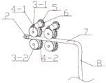
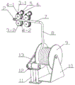
FIG. 2 is a schematic structural diagram of the retractable drill rod inner wall cleaning mechanism of the present invention;
FIG. 3 is a schematic view of the drive portion clamping the water pipe;
fig. 4 is a cross-sectional view of the high pressure showerhead.
In the figure: 1. the device comprises a drill rod, 2 parts of a high-pressure spray head, 3-1 parts of a friction wheel, 3-2 parts of a friction wheel, 4-1 parts of a driven gear, 4-2 parts of a driven gear, 5 parts of a miniature speed reducing motor, 6 parts of a driving gear, 7 parts of a rigid high-pressure water pipe, 8 parts of a flexible high-pressure water pipe, 9 parts of a roller, 10 parts of a roller bracket, 11 parts of a motor support, 12 parts of a speed reducing motor, 13 parts of a belt and a belt pulley.
Detailed Description
In order to make the objects, technical solutions and advantages of the present invention more clearly understood, the present invention is further described below with reference to the accompanying drawings.
As shown in fig. 1-3, the utility model provides a retractable drill rod inner wall cleaning mechanism, which mainly comprises an inner wall cleaning part, a driving part and a water pipe winding part; the inner wall cleaning part comprises a high-pressure spray head 2, a rigid high-pressure water pipe 7 and a soft high-pressure water pipe 8, one end of the rigid high-pressure water pipe 7 is connected with the high-pressure spray head 2, and the other end of the rigid high-pressure water pipe is fixedly connected with the soft high-pressure water pipe 8; the driving parts are two groups which are completely identical and fixed on the same horizontal line, wherein one group comprises a micro speed reducing motor 5, a driving gear 6, driven gears 4-1 and 4-2 and friction wheels 3-1 and 3-2, the micro speed reducing motor 5 is connected with the driving gear 6, the friction wheels 3-1 and 3-2 are respectively connected and fixed with one driven gear 4-1 and 4-2, the driving gear 6 is meshed with the driven gear 4-1, and the two driven gears 4-1 are meshed with the driving gear 4-2; the water pipe winding part comprises a roller 9, a roller support 10, a speed reducing motor 12, a motor support 11, a belt and a belt pulley 13, the speed reducing motor 12 is fixed on the motor support 11, the roller 9 is installed on the roller support 10, and a central shaft of the roller 9 is connected with the speed reducing motor 12 through the belt and the belt pulley 13.
When the drill rod is conveyed to the front of the mechanism, the speed reducing motor 12 drives the roller 9 through a belt and a belt pulley 13, the miniature speed reducing motor 5 drives the friction wheels 3-1 and 3-2 through the driving gear 6 and the driven gears 4-1 and 4-2, the other group of driving parts are the same, so that the high-pressure spray head 2 is pushed forwards, after entering the drill rod, high-pressure water flow is released to wash the inner wall of the drill rod, the movement trend of the high-pressure spray head 2 is kept forwards by the reverse acting force provided by the lateral water flow sprayed by the high-pressure spray head 2 until the high-pressure spray head 2 passes through the drill rod 1, the miniature speed reducing motor 5 and the speed reducing motor 12 rotate reversely to withdraw the high-pressure spray head 2.
In the scheme, a gap is formed between the friction wheels 3-1 and 3-2 and is smaller than the diameters of the rigid high-pressure water pipe 7 and the flexible high-pressure water pipe 8.
In the above scheme, the high-pressure nozzle 2 needs to be aligned with the axis of the drill rod 1 when being installed.
In the above scheme, the length of the rigid high-pressure water pipe 7 should be greater than the minimum distance from the high-pressure nozzle 2 to the drill rod 1, and the length of the flexible high-pressure water pipe 8 should be greater than the length of the drill rod 1.
In the scheme, the water flow spraying direction of the high-pressure spray head 2 is inclined backwards, and an included angle of 60 degrees is formed between the water flow spraying direction and the inner wall of the drill rod 1.
In the scheme, the linear speed of the friction wheels 3-1 and 3-2 is consistent with that of the roller 9.
While the preferred embodiment and the basic principles of the present invention have been described in detail, it will be understood by those skilled in the art that the invention is not limited to the embodiments described above, but is capable of various equivalent modifications and substitutions without departing from the spirit of the invention.

Claims (8)

1.一种可收缩式钻杆内壁清洗机构,其特征在于,包括:内壁清洗部分、驱动部分、水管缠绕部分;1. a retractable drill pipe inner wall cleaning mechanism, is characterized in that, comprises: inner wall cleaning part, driving part, water pipe winding part; 所述内壁清洗部分包括高压喷头(2)、刚性高压水管(7)、软性高压水管(8);The inner wall cleaning part includes a high-pressure spray head (2), a rigid high-pressure water pipe (7), and a soft high-pressure water pipe (8); 所述驱动部分共两组且相同,一组中包括微型减速电机(5)、主动齿轮(6)、从动齿轮(4-1)与(4-2)、摩擦轮(3-1)与(3-2);The driving parts are divided into two groups and are identical, and one group includes a micro reduction motor (5), a driving gear (6), driven gears (4-1) and (4-2), friction wheels (3-1) and (3-2); 所述水管缠绕部分包括滚筒(9)、减速电机(12)、皮带及皮带轮(13)。The water pipe winding part includes a drum (9), a deceleration motor (12), a belt and a pulley (13). 2.根据权利要求1所述的可收缩式钻杆内壁清洗机构,其特征在于所述内壁清洗部分刚性高压水管(7)一端与高压喷头(2)相连接,另一端与软性高压水管(8)固定连接。2. The retractable drill pipe inner wall cleaning mechanism according to claim 1 is characterized in that one end of the rigid high-pressure water pipe (7) of the inner wall cleaning part is connected with the high-pressure nozzle (2), and the other end is connected with the soft high-pressure water pipe (7). 8) Fixed connection. 3.根据权利要求1所述的可收缩式钻杆内壁清洗机构,其特征在于所述驱动部分微型减速电机(5)与主动齿轮(6)连接,摩擦轮(3-1)与(3-2)分别连接固定一个从动齿轮(4-1)与(4-2),主动齿轮(6)与从动齿轮(4-1)啮合,两个从动齿轮(4-1)与(4-2)啮合。3. The retractable drill pipe inner wall cleaning mechanism according to claim 1 is characterized in that the driving part miniature reduction motor (5) is connected with the driving gear (6), and the friction wheel (3-1) is connected with the (3- 2) Connect and fix a driven gear (4-1) and (4-2) respectively, the driving gear (6) meshes with the driven gear (4-1), and the two driven gears (4-1) and (4) -2) Meshing. 4.根据权利要求1所述的可收缩式钻杆内壁清洗机构,其特征在于所述水管缠绕部分滚减速电机(12)固定在电机支座(11)上,滚筒(9)安装在滚筒支架(10)上,滚筒(9)中心轴与减速电机(12)通过皮带及皮带轮(13)连接。4. The retractable drill pipe inner wall cleaning mechanism according to claim 1, characterized in that the rolling deceleration motor (12) of the water pipe winding part is fixed on the motor support (11), and the drum (9) is installed on the drum support On (10), the central axis of the drum (9) is connected with the deceleration motor (12) through a belt and a pulley (13). 5.根据权利要求1所述的可收缩式钻杆内壁清洗机构,其特征在于所述摩擦轮(3-1)与(3-2)之间设有间隙且小于刚性高压水管(7)和软性高压水管(8)直径。5. The retractable drill pipe inner wall cleaning mechanism according to claim 1, characterized in that a gap is provided between the friction wheels (3-1) and (3-2) and is smaller than the rigid high-pressure water pipe (7) and the The diameter of the flexible high-pressure water pipe (8). 6.根据权利要求1所述的可收缩式钻杆内壁清洗机构,其特征在于所述刚性高压水管(7)长度应大与高压喷头(2)到钻杆(1)的最小距离,所述软性高压水管(8)长度应大于钻杆(1)长度。6. The retractable drill pipe inner wall cleaning mechanism according to claim 1, characterized in that the length of the rigid high-pressure water pipe (7) should be greater than the minimum distance from the high-pressure nozzle (2) to the drill pipe (1), the The length of the flexible high-pressure water pipe (8) should be greater than the length of the drill pipe (1). 7.根据权利要求1所述的可收缩式钻杆内壁清洗机构,其特征在于所述高压喷头(2)水流喷射方向应斜向后,且与钻杆(1)内壁呈60度夹角。7. The retractable drill pipe inner wall cleaning mechanism according to claim 1, characterized in that the water jet direction of the high pressure nozzle (2) should be obliquely backward, and form an included angle of 60 degrees with the drill pipe (1) inner wall. 8.根据权利要求1所述的可收缩式钻杆内壁清洗机构,其特征在于所述摩擦轮(3-1)与(3-2)线速度与滚筒(9)线速度应保持一致。8. The retractable drill pipe inner wall cleaning mechanism according to claim 1, characterized in that the linear speed of the friction wheels (3-1) and (3-2) should be consistent with the linear speed of the drum (9).
CN202021003407.7U 2020-06-04 2020-06-04 Retractable drill pipe inner wall cleaning mechanism Expired - Fee Related CN212329151U (en)

Priority Applications (1)

Application Number Priority Date Filing Date Title
CN202021003407.7U CN212329151U (en) 2020-06-04 2020-06-04 Retractable drill pipe inner wall cleaning mechanism

Applications Claiming Priority (1)

Application Number Priority Date Filing Date Title
CN202021003407.7U CN212329151U (en) 2020-06-04 2020-06-04 Retractable drill pipe inner wall cleaning mechanism

Publications (1)

Publication Number Publication Date
CN212329151U true CN212329151U (en) 2021-01-12

Family

ID=74075313

Family Applications (1)

Application Number Title Priority Date Filing Date
CN202021003407.7U Expired - Fee Related CN212329151U (en) 2020-06-04 2020-06-04 Retractable drill pipe inner wall cleaning mechanism

Country Status (1)

Country Link
CN (1) CN212329151U (en)

Cited By (2)

* Cited by examiner, † Cited by third party
Publication number Priority date Publication date Assignee Title
CN116237317A (en) * 2022-11-18 2023-06-09 浙江工业大学 A flushing device for the inner wall of a large-diameter stainless steel pipe
CN121878861A (en) * 2026-03-20 2026-04-17 东营市垦利区黄河机械加工有限公司 Be used for oil field oil pipe siphunculus verifying attachment

Cited By (3)

* Cited by examiner, † Cited by third party
Publication number Priority date Publication date Assignee Title
CN116237317A (en) * 2022-11-18 2023-06-09 浙江工业大学 A flushing device for the inner wall of a large-diameter stainless steel pipe
CN121878861A (en) * 2026-03-20 2026-04-17 东营市垦利区黄河机械加工有限公司 Be used for oil field oil pipe siphunculus verifying attachment
CN121878861B (en) * 2026-03-20 2026-06-16 东营市垦利区黄河机械加工有限公司 Be used for oil field oil pipe siphunculus verifying attachment

Similar Documents

Publication Publication Date Title
CN105795995B (en) A high-rise wall cleaning robot
CN109047200B (en) Fluid-driven self-adaptive pipeline jet cleaner
CN200998723Y (en) Oil pipe cleaning device
CN111974761B (en) A device for cleaning the inner and outer walls of steel pipes at close range after pickling
CN205667532U (en) A kind of high-rise wall surface cleaning robot
CN105478420B (en) Tube cleaning arrangement
CN210146531U (en) A cleaning device for pretreatment of metal workpieces
CN208928783U (en) A kind of fluid driving self-adapting pipe injecting cleaning device
CN109092814A (en) A kind of water-electricity mixed power high-pressure jet tube cleaning arrangement
CN218014667U (en) Pipeline cleaning device for hydraulic engineering
CN203917426U (en) A kind of cleaner for inner wall of steel pipe
CN115013639A (en) A variable-length robot for jet cleaning of the inner wall of a pipe
CN118477767B (en) A high pressure jet nozzle
CN218797889U (en) Spiral propelling pipe cleaner for natural gas pipeline
CN110420942B (en) Hose cleaner
CN116351820A (en) A pressure pipeline inner wall automatic cleaning robot
CN220295409U (en) Pipeline pretreatment equipment
CN112170397A (en) Long distance oil pipeline cleaning device and cleaning vehicle
CN219253413U (en) Compressor valve cleaning machine
CN212397530U (en) Portable dissolving out pipeline cleaning machine
CN114888002A (en) Universal type metal elbow inner wall high-pressure water rust removal device and use method thereof
CN220704732U (en) A water supply and drainage equipment cleaning machine
CN221288937U (en) Tap water pipeline cleaning device
CN219541162U (en) Motor part belt cleaning device convenient to wash tubular part
CN209205964U (en) Oil pipe descaling device

Legal Events

Date Code Title Description
GR01 Patent grant
GR01 Patent grant
CF01 Termination of patent right due to non-payment of annual fee

Granted publication date: 20210112

Termination date: 20210604