CN212312613U - Extraction structure mould convenient for product forming - Google Patents
Extraction structure mould convenient for product forming Download PDFInfo
- Publication number
- CN212312613U CN212312613U CN202020852442.XU CN202020852442U CN212312613U CN 212312613 U CN212312613 U CN 212312613U CN 202020852442 U CN202020852442 U CN 202020852442U CN 212312613 U CN212312613 U CN 212312613U
- Authority
- CN
- China
- Prior art keywords
- mould
- product
- board
- plate
- long
- Prior art date
- Legal status (The legal status is an assumption and is not a legal conclusion. Google has not performed a legal analysis and makes no representation as to the accuracy of the status listed.)
- Active
Links
- 238000000605 extraction Methods 0.000 title claims description 7
- 238000007493 shaping process Methods 0.000 claims abstract description 19
- 238000000465 moulding Methods 0.000 claims description 29
- 239000003292 glue Substances 0.000 claims description 11
- 229920003023 plastic Polymers 0.000 abstract description 13
- 239000004033 plastic Substances 0.000 abstract description 13
- 239000000463 material Substances 0.000 abstract description 9
- 230000005574 cross-species transmission Effects 0.000 abstract description 2
- 239000000969 carrier Substances 0.000 abstract 2
- 238000002347 injection Methods 0.000 description 6
- 239000007924 injection Substances 0.000 description 6
- 238000001746 injection moulding Methods 0.000 description 6
- 230000000694 effects Effects 0.000 description 4
- 230000002349 favourable effect Effects 0.000 description 3
- 238000010438 heat treatment Methods 0.000 description 3
- 230000003321 amplification Effects 0.000 description 1
- 238000005336 cracking Methods 0.000 description 1
- 238000003199 nucleic acid amplification method Methods 0.000 description 1
- 238000012856 packing Methods 0.000 description 1
- 239000000243 solution Substances 0.000 description 1
- 238000006467 substitution reaction Methods 0.000 description 1
Images


Landscapes
- Moulds For Moulding Plastics Or The Like (AREA)
Abstract
The utility model discloses a draw forth structure mould convenient to product shaping, including three plate mould die carriers, three plate mould die carriers include upper fixed plate, runner plate, A board, B board, mould foot, thimble board and bottom plate, be provided with elongated mould benevolence core on the B board, be provided with two long and thin one-tenth die cavity on the mould benevolence core, it is located the both sides of mould benevolence core wide side to become the die cavity, both sides the one end of the long side of one-tenth die cavity is provided with the flash tank, and the other end is provided with into gluey point, it is connected through the sprue that sets up on subchannel and the mould benevolence core to advance gluey point, the flash tank sets up to square groove. The utility model discloses can spill over unnecessary material when the product shaping through the flash tank that advances gluey tail end setting at long and thin product, appear weld mark and the phenomenon of fracture when preventing the product shaping, fill when helping the product to mould plastics and fill, the tail end exhaust is drawn forth, especially is fit for long and thin product shaping, can effectively shorten the fashioned cycle of product.
Description
Technical Field
The utility model relates to an injection mold field especially relates to a draw forth structure mould convenient to product shaping.
Background
At present, when an injection mold is used for molding a slender product, weld marks are easy to appear at one end, which is far away from a glue inlet point, of the injection mold, even the molded product is cracked seriously, the reason is that the temperature of the flowing front end of the plastic is reduced because the hot-melted plastic flows in a molding cavity for too long time, cold materials cannot be fused together at the tail end of the molded product, and therefore the weld marks and the cracking phenomenon are formed in the product. In view of the above, there is a need to develop a structure for guiding out the cold material at the front end of the product forming cavity.
SUMMERY OF THE UTILITY MODEL
The utility model aims to overcome the above problem that prior art exists, provide a draw forth structure mould convenient to product shaping, the utility model relates to a novelty, rational in infrastructure, compare with prior art, can overflow the unnecessary material of front end when product shaping through the flash tank that advances gluey tail end setting at long and thin product, appear the phenomenon of weld mark and fracture when preventing product shaping, fill when helping the product to mould plastics and fill, the tail end exhaust is drawn forth, especially is fit for long and thin product shaping, can effectively shorten product shaping's cycle.
For realizing above-mentioned technical purpose, reach above-mentioned technological effect, the utility model discloses a following technical scheme realizes:
the utility model provides a draw forth structure mould convenient to product shaping, includes three plate die carrier, three plate die carrier includes upper fixed plate, runner plate, A board, B board, mould foot, thimble board and bottom plate, be provided with elongated mould benevolence core on the B board, be provided with two elongated shaping chambeies on the mould benevolence core, the shaping chamber is located the both sides of mould benevolence core broadside, both sides the one end of shaping chamber long side is provided with the flash tank, and the other end is provided with into gluey point, it is connected through the sprue that sets up on subchannel and the mould benevolence core to advance gluey point, the flash tank sets up to square groove, the bottom of square groove is provided with the thimble hole, and its square groove is provided with the discharge opening with the one side that becomes the chamber and. By adopting the technical scheme, the flash port is used for flash when a product is molded; the flash tank is used for storing materials; the product is when injection moulding, the plastic after its heating is melted is injected the mould through the injection machine and is irritated the mouth on, flow to the sprue by the perpendicular runner on irritating the mouth, the subchannel of rethread sprue runner both sides, then, enter into the molding cavity through the point of advancing on the subchannel, fill to the other end by the one end in molding cavity, treat that the molding cavity fills the back, the plastic that enters into the molding cavity at first enters into the other end in molding cavity, enter into the flash tank through the flash mouth under the pressure effect, thereby be favorable to product injection moulding, reduce the fracture phenomenon that the product leads to because of the cold burden. Wherein, the flash tank is kept away from one side of flash mouth and still is provided with the air discharge duct, helps the packing and the exhaust of shaping chamber. The depth of the air discharge groove is set at 0.015 mm. The length is set at 3-5 mm.
Preferably, the flash opening is a horn-shaped flash opening, the angles of the left side and the right side of the horn-shaped flash opening are set to be 15-30 degrees, and the angle of the bottom of the horn-shaped flash opening is set to be 3-12 degrees. By adopting the technical scheme, glue overflow and flowing of the glue overflow during product molding are facilitated.
Preferably, the width of one side of the overflow port connected with the forming cavity is set to be 2-5mm, and the depth is set to be 0.15-0.5 mm. By adopting the technical scheme, the flash is convenient to remove or cut off when the product is formed and after the product is formed.
Preferably, the demolding angle of the overflow opening is set to be 3-10 degrees. By adopting the technical scheme, the demolding is convenient.
Preferably, the width of the square groove is not less than 1/3 of the width of the forming cavity, the depth is set to be 2-3mm, and the demoulding angle of the four sides of the square groove is set to be 5-15 degrees. By adopting the technical scheme, the material storage and the demoulding after the forming are convenient.
Preferably, the square groove is positioned in the middle of the forming cavity. By adopting the technical scheme, the molten plastic can flow and overflow conveniently.
The utility model has the advantages that: novel in design, rational in infrastructure, compare with prior art, can spill over unnecessary material through the flash tank that advances gluey tail end setting at long and thin product when the product shaping, the phenomenon of weld mark and fracture appears when preventing the product shaping, fill when helping the product to mould plastics and fill, the tail end is discharged and is drawn forth, especially is fit for long and thin product shaping, can effectively shorten the fashioned cycle of product.
The foregoing description is only an overview of the technical solutions of the present invention, and in order to make the technical means of the present invention more clearly understood and to be implemented according to the content of the description, the following detailed description is given with reference to the preferred embodiments of the present invention and the accompanying drawings. The detailed description of the present invention is given by the following examples and the accompanying drawings.
Drawings
The accompanying drawings, which are included to provide a further understanding of the invention and are incorporated in and constitute a part of this application, illustrate embodiment(s) of the invention and together with the description serve to explain the invention without undue limitation to the invention. In the drawings:
FIG. 1 is a schematic view of a mold core structure according to the present invention;
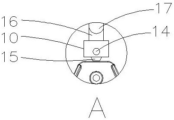
fig. 2 is a schematic view of a local amplification structure related to the present invention:
fig. 3 is a schematic view of the mold frame according to the present invention.
The reference numbers in the figures illustrate: the mold comprises an upper fixing plate 1, a runner plate 2, an A plate 3, a B plate 4, mold feet 5, an ejector plate 6, a lower fixing plate 7, a mold core 8, a molding cavity 9, a flash tank 10, a glue inlet point 11, a sub-runner 12, a main runner 13, a top needle hole 14, a flash port 15, an exhaust groove 16 and an exhaust avoiding groove 17.
Detailed Description
The invention is further described with reference to the accompanying drawings:
referring to fig. 1 to 3, a drawing structure die convenient for product forming comprises a three-plate die frame, wherein the three-plate die frame comprises an upper fixing plate 1, a runner plate 2, an a plate 3, a B plate 4, a die leg 5, an ejector plate 6 and a lower fixing plate 7, a long die core 8 is arranged on the B plate 4, two long and thin forming cavities 9 are arranged on the die core 8, the forming cavities 9 are located on two sides of the wide side of the die core 8, one end of the long side of the forming cavity 9 is provided with a flash groove 10, the other end of the long side of the forming cavity 9 is provided with a glue inlet point 11, the glue inlet point 11 is connected with a main runner 13 arranged on the die core 8 through a runner 12, the flash groove 10 is a square groove, the bottom of the square groove is provided with an ejector pin hole 14, and one side of the square groove connected with the forming cavity 9 is provided with a flash. By adopting the technical scheme, the flash port 15 is used for flash when a product is molded; the flash tank 10 is used for storing materials; concretely, the product is when injection moulding, the plastic after its heating is melted passes through the injection machine and injects the mould on irritating the mouth, flow to sprue 13 by the perpendicular runner on irritating the mouth, the subchannel 12 of 13 runners both sides of rethread sprue, then, enter into the molding cavity 9 through advancing gluey point 11 on the subchannel 12, fill to the other end by the one end of molding cavity 9, treat that molding cavity 9 fills the back, the plastic that enters into molding cavity 9 at first enters into the other end of molding cavity 9, enter into flash tank 10 through flash mouth 15 under the pressure effect, thereby be favorable to product injection moulding, reduce the fracture phenomenon that the product leads to because of the cold charge. Wherein, the side of the flash groove 10 far away from the flash opening 15 is also provided with an exhaust groove 16, which is helpful for filling and exhausting the molding cavity 9. The depth of the air discharge groove 16 was set at 0.015 mm. The length is set at 3-5 mm.
Preferably, the flash opening 15 is a horn-shaped flash opening, the angle of the left side and the right side of the horn-shaped flash opening is set to be 15-30 degrees, and the angle of the bottom of the horn-shaped flash opening is set to be 3-12 degrees. By adopting the technical scheme, glue overflow and flowing of the glue overflow during product molding are facilitated.
Preferably, the width of the side of the overflow opening 15 connected with the forming cavity 9 is set to be 2-5mm, and the depth is set to be 0.15-0.5 mm. By adopting the technical scheme, the flash is convenient to remove or cut off when the product is formed and after the product is formed.
Preferably, the demolding angle of the overflow opening 15 is set to be 3-10 degrees. By adopting the technical scheme, the demolding is convenient.
Preferably, the width of the square groove is not less than 1/3 of the width of the molding cavity 9, the depth is set to be 2-3mm, and the demolding angle of the four sides of the square groove is set to be 5-15 degrees. By adopting the technical scheme, the material storage and the demoulding after the forming are convenient.
Preferably, said square groove is located in the middle of the forming chamber 9. By adopting the technical scheme, the molten plastic can flow and overflow conveniently.
DETAILED DESCRIPTION OF EMBODIMENT (S) OF INVENTION
The product is when injection moulding, the plastic after its heating is melted passes through the injection machine and injects the mould on irritating the mouth, flow to the sprue by the perpendicular runner on irritating the mouth, the subchannel of rethread sprue runner both sides, then, enter into the molding chamber through the point of advancing on the subchannel and glue, fill to the other end by the one end in molding chamber, treat that the molding chamber fills the back, the plastic that most advanced goes into the molding chamber enters into the other end in molding chamber, enter into the flash tank through the flash mouth under the pressure effect, thereby be favorable to product injection moulding, reduce weld mark and the fracture phenomenon that the product leads to because of the cold burden.
The above description is only for the specific embodiments of the present invention, but the protection scope of the present invention is not limited thereto, and any person skilled in the art can easily think of the changes or substitutions within the technical scope of the present invention, and all should be covered within the protection scope of the present invention. Therefore, the protection scope of the present invention shall be subject to the protection scope of the claims.
Claims (6)
1. The utility model provides a draw forth structure mould convenient to product shaping, includes three board die carrier, three board die carrier includes upper fixed plate (1), runner plate (2), A board (3), B board (4), mould foot (5), thimble board (6) and bottom plate (7), its characterized in that: the mould core forming device is characterized in that a long mould core (8) is arranged on the B plate (4), two long and thin forming cavities (9) are arranged on the mould core (8), the forming cavities (9) are located on two sides of the wide side of the mould core (8), two sides are arranged on one end of the long side of the forming cavity (9) and are provided with overflow troughs (10), the other end of the forming cavity is provided with a glue inlet point (11), the glue inlet point (11) is connected with a main runner (13) arranged on the mould core (8) through a sub-runner (12), the overflow troughs (10) are arranged into square troughs, the bottom of each square trough is provided with a thimble hole (14), and one side of each square trough, which is connected with the forming cavity (9), is provided with an overflow.
2. The extraction structure mold for product molding of claim 1, wherein: the flash opening (15) is arranged to be a horn-shaped flash opening, the angles of the left side and the right side of the horn-shaped flash opening are arranged to be 15-30 degrees, and the angle of the bottom of the horn-shaped flash opening is arranged to be 3-12 degrees.
3. The extraction structure mold for product molding of claim 1, wherein: the width of one side of the overflow opening (15) connected with the molding cavity (9) is set to be 2-5mm, and the depth is set to be 0.15-0.5 mm.
4. The extraction structure mold for product molding of claim 1, wherein: the demoulding angle of the overflow opening (15) is set to be 3-10 degrees.
5. The extraction structure mold for product molding of claim 1, wherein: the width of the square groove is not less than 1/3 of the width of the molding cavity (9), the depth is set to be 2-3mm, and the demolding angle of the four sides of the square groove is set to be 5-15 degrees.
6. The extraction structure mold for product molding of claim 1, wherein: the square groove is positioned in the middle of the forming cavity (9).
Priority Applications (1)
| Application Number | Priority Date | Filing Date | Title |
|---|---|---|---|
| CN202020852442.XU CN212312613U (en) | 2020-05-20 | 2020-05-20 | Extraction structure mould convenient for product forming |
Applications Claiming Priority (1)
| Application Number | Priority Date | Filing Date | Title |
|---|---|---|---|
| CN202020852442.XU CN212312613U (en) | 2020-05-20 | 2020-05-20 | Extraction structure mould convenient for product forming |
Publications (1)
| Publication Number | Publication Date |
|---|---|
| CN212312613U true CN212312613U (en) | 2021-01-08 |
Family
ID=74022494
Family Applications (1)
| Application Number | Title | Priority Date | Filing Date |
|---|---|---|---|
| CN202020852442.XU Active CN212312613U (en) | 2020-05-20 | 2020-05-20 | Extraction structure mould convenient for product forming |
Country Status (1)
| Country | Link |
|---|---|
| CN (1) | CN212312613U (en) |
Cited By (1)
| Publication number | Priority date | Publication date | Assignee | Title |
|---|---|---|---|---|
| CN115958178A (en) * | 2023-01-12 | 2023-04-14 | 浙江赛豪实业有限公司 | Mold flash exhaust structure |
-
2020
- 2020-05-20 CN CN202020852442.XU patent/CN212312613U/en active Active
Cited By (1)
| Publication number | Priority date | Publication date | Assignee | Title |
|---|---|---|---|---|
| CN115958178A (en) * | 2023-01-12 | 2023-04-14 | 浙江赛豪实业有限公司 | Mold flash exhaust structure |
Similar Documents
| Publication | Publication Date | Title |
|---|---|---|
| CN213137657U (en) | An injection mold structure with an overflow gate | |
| CN207841940U (en) | A kind of uniform injection mold of material feeding | |
| CN214448079U (en) | High-precision hot runner mold for optical lens | |
| CN105150464A (en) | Injection die with heat insulating runner | |
| CN207028047U (en) | A gas-assisted injection molding structure | |
| CN208164209U (en) | The continuous injection molding of the large capacity high pressure bitubular | |
| CN207841943U (en) | A kind of injection mold with material injecting mechanism | |
| CN210758872U (en) | Plastic comb preparation mould | |
| CN210733055U (en) | Hot runner injection mold | |
| CN115339058A (en) | Injection mold and method for thin-walled plastic parts | |
| CN211031046U (en) | Sectional type high-speed injection molding mold | |
| CN216609835U (en) | Water-saving orifice material injection mold | |
| CN222201452U (en) | Three-plate spot-casting structure of integrated injection mold for rubber and iron | |
| CN211440940U (en) | Multi-cavity injection mold | |
| CN111070580A (en) | Method and mold for shunting and side-pouring hot runner | |
| CN217047325U (en) | Full-hot multi-head needle valve hot nozzle suitable for injection molding of small products | |
| CN218749075U (en) | Side income formula is moulded plastics and is advanced gluey system | |
| CN219632562U (en) | Die casting die for cylinder cover | |
| CN218615173U (en) | Heat preservation mechanism and injection mold | |
| CN216885001U (en) | Floatable discharge needle for gas-assisted injection molding | |
| CN220923146U (en) | Injection mold with high filling degree | |
| CN222198845U (en) | Lead core box body injection mold | |
| CN216299933U (en) | Low-pressure injection mold for automobile manufacturing | |
| CN216465964U (en) | Plastic toy injection mold of high leakproofness | |
| CN211968239U (en) | Passenger car pedal bracket plastic part injection mold |
Legal Events
| Date | Code | Title | Description |
|---|---|---|---|
| GR01 | Patent grant | ||
| GR01 | Patent grant |