CN212305230U - Fixed adjustable photovoltaic tracking support and photovoltaic tracking system - Google Patents
Fixed adjustable photovoltaic tracking support and photovoltaic tracking system Download PDFInfo
- Publication number
- CN212305230U CN212305230U CN202021236473.9U CN202021236473U CN212305230U CN 212305230 U CN212305230 U CN 212305230U CN 202021236473 U CN202021236473 U CN 202021236473U CN 212305230 U CN212305230 U CN 212305230U
- Authority
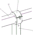
- CN
- China
- Prior art keywords
- push rod
- photovoltaic tracking
- fixed
- electric push
- tracking support
- Prior art date
- Legal status (The legal status is an assumption and is not a legal conclusion. Google has not performed a legal analysis and makes no representation as to the accuracy of the status listed.)
- Active
Links
Images




Classifications
-
- Y—GENERAL TAGGING OF NEW TECHNOLOGICAL DEVELOPMENTS; GENERAL TAGGING OF CROSS-SECTIONAL TECHNOLOGIES SPANNING OVER SEVERAL SECTIONS OF THE IPC; TECHNICAL SUBJECTS COVERED BY FORMER USPC CROSS-REFERENCE ART COLLECTIONS [XRACs] AND DIGESTS
- Y02—TECHNOLOGIES OR APPLICATIONS FOR MITIGATION OR ADAPTATION AGAINST CLIMATE CHANGE
- Y02E—REDUCTION OF GREENHOUSE GAS [GHG] EMISSIONS, RELATED TO ENERGY GENERATION, TRANSMISSION OR DISTRIBUTION
- Y02E10/00—Energy generation through renewable energy sources
- Y02E10/40—Solar thermal energy, e.g. solar towers
- Y02E10/47—Mountings or tracking
-
- Y—GENERAL TAGGING OF NEW TECHNOLOGICAL DEVELOPMENTS; GENERAL TAGGING OF CROSS-SECTIONAL TECHNOLOGIES SPANNING OVER SEVERAL SECTIONS OF THE IPC; TECHNICAL SUBJECTS COVERED BY FORMER USPC CROSS-REFERENCE ART COLLECTIONS [XRACs] AND DIGESTS
- Y02—TECHNOLOGIES OR APPLICATIONS FOR MITIGATION OR ADAPTATION AGAINST CLIMATE CHANGE
- Y02E—REDUCTION OF GREENHOUSE GAS [GHG] EMISSIONS, RELATED TO ENERGY GENERATION, TRANSMISSION OR DISTRIBUTION
- Y02E10/00—Energy generation through renewable energy sources
- Y02E10/50—Photovoltaic [PV] energy
Landscapes
- Photovoltaic Devices (AREA)
Abstract
本实用新型涉及光伏领域,公开了一种固定可调光伏跟踪支架,包括:间隔设置的多个立柱;横梁,横梁与多个立柱的顶部连接,并可相对多个立柱转动;至少两个驱动机构,驱动机构包括电动推杆和推杆臂,电动推杆的固定端与立柱枢接,电动推杆的自由端与推杆臂的一端枢接,推杆臂的另一端与横梁连接;两个相邻的电动推杆分别安装在两个立柱上。本实用新型通过优化光伏跟踪支架的安装结构,使得光伏跟踪支架的现场施工更加快捷,同时确保光伏跟踪支架的结构稳定性,通过电动推杆的伸缩带动推杆臂,从而带动横梁在立柱上转动,以调整固定在横梁上的光伏组件的角度。本实用新型还公开了一种应用上述固定可调光伏跟踪支架的光伏跟踪系统。

The utility model relates to the field of photovoltaics, and discloses a fixed and adjustable photovoltaic tracking support, comprising: a plurality of vertical columns arranged at intervals; a cross beam, which is connected with the tops of the plurality of vertical columns and can be rotated relative to the plurality of vertical columns; at least two driving The drive mechanism includes an electric push rod and a push rod arm, the fixed end of the electric push rod is pivotally connected to the column, the free end of the electric push rod is pivotally connected to one end of the push rod arm, and the other end of the push rod arm is connected to the beam; two Two adjacent electric push rods are respectively installed on the two uprights. By optimizing the installation structure of the photovoltaic tracking support, the utility model makes the on-site construction of the photovoltaic tracking support faster, and at the same time ensures the structural stability of the photovoltaic tracking support. , to adjust the angle of the photovoltaic modules fixed on the beam. The utility model also discloses a photovoltaic tracking system using the above-mentioned fixed and adjustable photovoltaic tracking support.
Description
技术领域technical field
本实用新型涉及光伏领域,尤指一种固定可调光伏跟踪支架及光伏跟踪系统。The utility model relates to the field of photovoltaics, in particular to a fixed and adjustable photovoltaic tracking bracket and a photovoltaic tracking system.
背景技术Background technique
光伏跟踪支架是用来固定光伏组件的,在通过光伏组件吸收太阳光的能量时,需要将光伏组件固定在光伏跟踪支架上,以使光伏组件的吸收面朝向太阳光的方向,从而达到充分利用太阳能的目的。Photovoltaic tracking brackets are used to fix photovoltaic modules. When absorbing the energy of sunlight through photovoltaic modules, photovoltaic modules need to be fixed on the photovoltaic tracking brackets, so that the absorption surface of photovoltaic modules faces the direction of sunlight, so as to achieve full utilization purpose of solar energy.
目前的光伏跟踪支架结构复杂,导致光伏跟踪支架的现场施工安装速度慢,并且随着季节的变化,需要对光伏跟踪支架进行一定的调整,而由于复杂的结构,导致光伏跟踪支架的调节变得困难。The current photovoltaic tracking bracket has a complex structure, which leads to a slow on-site construction and installation of the photovoltaic tracking bracket, and with the change of seasons, it is necessary to adjust the photovoltaic tracking bracket to a certain extent. Due to the complex structure, the adjustment of the photovoltaic tracking bracket becomes difficulty.
实用新型内容Utility model content
本实用新型的目的是提供一种固定可调光伏跟踪支架及光伏跟踪系统,实现了光伏跟踪支架的快捷安装,在保证光伏跟踪支架具有稳定结构的同时,实现了光伏跟踪支架的快速调节。The purpose of the utility model is to provide a fixed and adjustable photovoltaic tracking bracket and a photovoltaic tracking system, which realizes the quick installation of the photovoltaic tracking bracket, and realizes the rapid adjustment of the photovoltaic tracking bracket while ensuring that the photovoltaic tracking bracket has a stable structure.
本实用新型提供的技术方案如下:The technical scheme provided by the utility model is as follows:
一方面,提供一种固定可调光伏跟踪支架,包括:In one aspect, a fixed and adjustable photovoltaic tracking bracket is provided, including:
间隔设置的多个立柱;Multiple columns arranged at intervals;
横梁,所述横梁与多个所述立柱的顶部连接,并可相对多个所述立柱转动;a cross beam, the cross beam is connected with the tops of the plurality of the uprights, and can be rotated relative to the plurality of the uprights;
至少两个驱动机构,所述驱动机构包括电动推杆和推杆臂,所述电动推杆的固定端与所述立柱枢接,所述电动推杆的自由端与所述推杆臂的一端枢接,所述推杆臂的另一端与所述横梁连接;At least two drive mechanisms, the drive mechanisms include an electric push rod and a push rod arm, the fixed end of the electric push rod is pivotally connected to the upright column, and the free end of the electric push rod is connected to one end of the push rod arm pivotally connected, the other end of the push rod arm is connected with the beam;
两个相邻的所述电动推杆分别安装在两个所述立柱上,且两个相邻的所述推杆臂安装在两个所述立柱相互靠近或者相互远离的一侧,可限制所述横梁沿其轴线方向移动。The two adjacent electric push rods are respectively installed on the two uprights, and the two adjacent push rod arms are installed on the sides of the two uprights that are close to or away from each other, which can limit the The beam moves along its axis.
本方案中,横梁与立柱组成的支架结构可以用于快速安装光伏组件,同时横梁可以在立柱上转动,通过驱动机构的电动推杆的伸缩带动推杆臂,推杆臂带动横梁转动,从而实现固定在横梁上的光伏组件的调节,结构简单,调节方便,同时两个相邻的推杆臂可以限制横梁沿其轴向方向的移动,从而确保光伏跟踪支架调节的稳定性。In this solution, the bracket structure composed of the beam and the column can be used to quickly install the photovoltaic modules, and the beam can be rotated on the column at the same time. The adjustment of the photovoltaic module fixed on the beam has a simple structure and is convenient to adjust, and at the same time, two adjacent push rod arms can limit the movement of the beam along its axial direction, thereby ensuring the stability of the adjustment of the photovoltaic tracking bracket.
进一步优选地,所述推杆臂包括抱箍和两块连接板,所述抱箍与所述横梁可拆卸连接,两块所述连接板的一端分别设置在所述抱箍上,两块所述连接板的另一端分别设置有对应的第一安装孔,所述第一安装孔用于穿设与所述电动推杆的自由端枢接的转轴。Further preferably, the push rod arm includes a hoop and two connecting plates, the hoop is detachably connected to the beam, one ends of the two connecting plates are respectively arranged on the hoop, and the two connecting plates are respectively arranged on the hoop. The other ends of the connecting plates are respectively provided with corresponding first installation holes, and the first installation holes are used to pass through a rotating shaft pivotally connected with the free end of the electric push rod.
本方案中,推杆臂由抱箍和两块连接板组成,抱箍可拆卸地安装在横梁上,两块连接板的一端通过穿过第一安装孔的转轴与电动推杆的自由端枢接,优化了推杆臂的安装结构,使得现场施工变得更加快捷。In this solution, the push rod arm is composed of a hoop and two connecting plates, the hoop is detachably installed on the beam, and one end of the two connecting plates pivots with the free end of the electric push rod through the rotating shaft passing through the first installation hole The installation structure of the push rod arm is optimized, making the on-site construction faster.
进一步优选地,所述抱箍包括底板以及紧固在所述底板上的U型螺栓,两块所述连接板均采用L型板,两块所述L型板呈对称设置在所述底板上,两个所述第一安装孔分别设置在两块所述L型板相对设置的侧板上,两块所述L型板的顶板位于同一平面上,且两块所述L型板的顶板之间通过连接块连接。Further preferably, the hoop comprises a bottom plate and a U-shaped bolt fastened on the bottom plate, the two connecting plates are L-shaped plates, and the two L-shaped plates are symmetrically arranged on the bottom plate. , the two first mounting holes are respectively arranged on the opposite side plates of the two L-shaped plates, the top plates of the two L-shaped plates are located on the same plane, and the top plates of the two L-shaped plates are located on the same plane. connected by connecting blocks.
本方案中,两块连接板均采用L型板,电动推杆的自由端转动安装在两块 L型板之间,同时两块L型板的顶板还通过连接块连接在一起,加强了两块连接板的结构强度,提高了推杆臂的结构稳定性。In this scheme, the two connecting plates are both L-shaped plates, and the free end of the electric push rod is rotated and installed between the two L-shaped plates. The structural strength of the block connecting plate improves the structural stability of the push rod arm.
进一步优选地,所述底板上设置有呈矩形分布的四个固定孔,沿所述横梁的轴向设置的两个所述固定孔分别穿设有所述U型螺栓,所述U型螺栓的弯曲部卡接在所述横梁上,以固定所述底板与所述横梁。Further preferably, the bottom plate is provided with four fixing holes distributed in a rectangular shape, and the two fixing holes arranged along the axial direction of the beam are respectively provided with the U-shaped bolts. The bent portion is clamped on the beam to fix the bottom plate and the beam.
本方案中,底板通过两个U形螺栓实现与横梁的固定连接,底板贴合在横梁的一个侧面上,两个U形螺栓分别卡接在横梁的其它三个侧面上,从而当电动推杆带动推杆臂运动时,推杆臂即可带动横梁转动,安装结构简单。In this solution, the bottom plate is fixedly connected to the beam through two U-shaped bolts, the bottom plate is attached to one side of the beam, and the two U-shaped bolts are respectively clamped on the other three sides of the beam, so as to act as an electric push rod When driving the push rod arm to move, the push rod arm can drive the beam to rotate, and the installation structure is simple.
进一步优选地,所述驱动机构还包括推杆座,所述推杆座包括相互连接的第一固定板和第二固定板,所述第一固定板和所述第二固定板分别设置在所述立柱的相邻两个侧面上,所述第一固定板向所述第二固定板远离所述立柱的一侧延伸设置有连接部,所述连接部与所述电动推杆的固定端枢接。Further preferably, the drive mechanism further includes a push rod seat, the push rod seat includes a first fixing plate and a second fixing plate that are connected to each other, the first fixing plate and the second fixing plate are respectively arranged at the On the two adjacent sides of the vertical column, the first fixing plate is extended to the side of the second fixing plate away from the vertical column with a connecting part, and the connecting part is pivoted with the fixed end of the electric push rod. catch.
本方案中,电动推杆通过推杆座安装在立柱上,推杆座包括相互连接的第一固定板和第二固定板,第一固定板和第二固定板分别设置在立柱的两个相邻侧面上,其中第一固定板向第二固定板远离立柱的一侧延伸设置有连接部,电动推杆的固定端与连接部枢接,优化了电动推杆的安装结构,使得电动推杆的安装位置避开了立柱,而安装在立柱的一侧,从而避开了立柱对电动推杆安装时的影响。In this solution, the electric push rod is installed on the column through the push rod seat, and the push rod seat includes a first fixing plate and a second fixing plate that are connected to each other, and the first fixing plate and the second fixing plate are respectively arranged on two phases of the column. On the adjacent side, the first fixing plate is extended to the side of the second fixing plate away from the column and is provided with a connecting part, and the fixed end of the electric push rod is pivotally connected with the connecting part, which optimizes the installation structure of the electric push rod, so that the electric push rod The installation position avoids the column, and is installed on one side of the column, thereby avoiding the influence of the column on the installation of the electric push rod.
进一步优选地,所述连接部包括支撑板和两块安装板,所述支撑板与所述第一固定板位于同一平面上,两块所述安装板分别设置在所述支撑板远离所述立柱的一侧,两块所述安装板上分别设置有对应的第二安装孔,所述第二固定孔用于通过紧固件与所述电动推杆的固定端枢接。Further preferably, the connecting part includes a support plate and two mounting plates, the support plate and the first fixing plate are located on the same plane, and the two mounting plates are respectively arranged on the support plate away from the column. On one side of the mounting plate, corresponding second mounting holes are respectively provided on the two mounting plates, and the second fixing holes are used for pivotally connecting with the fixed end of the electric push rod through fasteners.
本方案中,连接部通过两块安装板与电动推杆的固定端枢接,在两块安装板上分别设置有第二安装孔,以通过紧固件将电动推杆的固定端转动安装在连接部上。In this solution, the connecting part is pivotally connected to the fixed end of the electric push rod through two mounting plates, and the two mounting plates are respectively provided with second installation holes, so that the fixed end of the electric push rod can be rotated and installed on the electric push rod through the fastener. on the connector.
进一步优选地,所述横梁由若干个方形管通过端部的连接件拼接设置而成,所述横梁上设置有轴承,所述立柱的顶端设置有轴承座,所述轴承安装在所述轴承座上,使所述横梁相对所述立柱可转动设置。Further preferably, the beam is formed by splicing a plurality of square tubes through connecting pieces at the ends, the beam is provided with a bearing, the top of the column is provided with a bearing seat, and the bearing is installed on the bearing seat. On the upper side, the beam is rotatably arranged relative to the upright column.
本方案中,为了适应固定安装光伏组件所需的横梁长度,横梁由若干个方形管通过端部的连接件进行拼接设置而成,横梁与立柱之间通过轴承进行连接,从而使横梁可以沿其自身的轴线方向转动,方便对光伏组件的角度进行调节。In this scheme, in order to adapt to the length of the beam required for the fixed installation of photovoltaic modules, the beam is formed by splicing several square tubes through connectors at the ends, and the beam and the column are connected by bearings, so that the beam can follow the The axis direction of its own rotates, which is convenient to adjust the angle of the photovoltaic module.
进一步优选地,多个所述电动推杆的固定端之间通过连杆连接,使多个所述电动推杆同步运动。Further preferably, the fixed ends of the plurality of electric push rods are connected by connecting rods, so that the plurality of electric push rods move synchronously.
本方案中,采用多个驱动机构对横梁上的光伏组件的角度进行调节,以适应在横梁上固定安装的不同长度的光伏组件的角度调节,多个电动推杆之间通过连杆进行连接,以保证多个电动推杆之间的运动同步性,确保光伏组件的角度调节的准确性。In this solution, multiple driving mechanisms are used to adjust the angle of the photovoltaic modules on the beam to adapt to the angle adjustment of photovoltaic modules of different lengths fixedly installed on the beam, and the plurality of electric push rods are connected by connecting rods. In order to ensure the movement synchronization between multiple electric actuators and the accuracy of the angle adjustment of the photovoltaic modules.
另一方面,还提供一种光伏跟踪系统,包括光伏组件、檩条、支撑件、斜撑件和上述的固定可调光伏跟踪支架,所述檩条通过所述支撑件与所述横梁固定连接,所述檩条的两端与所述支撑件的两端分别通过所述斜撑件连接。On the other hand, a photovoltaic tracking system is also provided, comprising photovoltaic components, purlins, supports, diagonal braces and the above-mentioned fixed and adjustable photovoltaic tracking bracket, wherein the purlins are fixedly connected with the beams through the supports, so The two ends of the purlin and the two ends of the support piece are respectively connected by the diagonal support piece.
本方案中,将光伏组件安装在光伏跟踪支架上形成光伏跟踪系统,可以通过光伏跟踪支架调节光伏组价的角度,以适应所在地的气候条件。In this solution, the photovoltaic modules are installed on the photovoltaic tracking bracket to form a photovoltaic tracking system, and the angle of the photovoltaic group price can be adjusted through the photovoltaic tracking bracket to adapt to the local climatic conditions.
进一步优选地,所述檩条采用C型钢制作而成,所述斜撑件采用L型冷弯角钢制作而成。Further preferably, the purlin is made of C-shaped steel, and the diagonal brace is made of L-shaped cold-formed angle steel.
本方案中,通过C型钢和L型冷弯角钢可以减少光伏组件安装时的单位用钢量,节约安装成本。In this solution, the C-shaped steel and L-shaped cold-formed angle steel can reduce the unit steel consumption during the installation of photovoltaic modules and save the installation cost.
本实用新型的技术效果在于:The technical effect of the present utility model is:
本实用新型通过横梁和立柱组成的支架结构来固定安装光伏组件,同时在横梁与立柱之间设置驱动机构,以调节安装在横梁上的光伏组件的角度,从而适应不同季节的光伏组件的使用,通过电动推杆和推杆臂优化了光伏跟踪支架的安装结构,同时方便对光伏跟踪支架进行调节,通过电动推杆的伸缩带动推杆臂,推杆臂再带动横梁转动,便可快速实现安装在横梁上的光伏组件的角度调节,并且通过简单的安装结构即可实现光伏组件的安装,还能保证整个光伏跟踪支架的结构稳定性。The utility model fixes and installs the photovoltaic modules through the bracket structure composed of the beam and the column, and at the same time, a driving mechanism is arranged between the beam and the column to adjust the angle of the photovoltaic module installed on the beam, so as to adapt to the use of the photovoltaic modules in different seasons, The installation structure of the photovoltaic tracking bracket is optimized through the electric push rod and the push rod arm, and at the same time, it is convenient to adjust the photovoltaic tracking support. The angle of the photovoltaic modules on the beam is adjusted, and the installation of the photovoltaic modules can be realized through a simple installation structure, and the structural stability of the entire photovoltaic tracking bracket can also be ensured.
附图说明Description of drawings
下面结合附图和具体实施方式对本实用新型作进一步详细说明:Below in conjunction with accompanying drawing and specific embodiment, the utility model is described in further detail:
图1是本实用新型的一种固定可调光伏跟踪支架的结构示意图;1 is a schematic structural diagram of a fixed and adjustable photovoltaic tracking support of the present invention;
图2是本实用新型的横梁上安装有檩条时的结构示意图;Fig. 2 is the structural representation when the purlin is installed on the beam of the present utility model;
图3是本实用新型的驱动机构的局部放大结构示意图;Fig. 3 is the partial enlarged structural schematic diagram of the drive mechanism of the present invention;
图4是本实用新型的推杆座的局部放大结构示意图;Fig. 4 is the partial enlarged structural schematic diagram of the push rod seat of the present invention;
图5是本实用新型的立柱与横梁连接处的局部放大结构示意图;Fig. 5 is the partial enlarged structural schematic diagram of the connection between the column and the beam of the present invention;
图6是本实用新型的横梁与檩条连接的局部放大结构示意图;Fig. 6 is the partial enlarged structural schematic diagram of the connection between the beam and the purlin of the present utility model;
图7是本实用新型的光伏组件的结构示意图。FIG. 7 is a schematic structural diagram of the photovoltaic module of the present invention.
附图标号说明:Description of reference numbers:
1.立柱,2.横梁,3.电动推杆,4.推杆臂,41.抱箍,41a.底板,41b.U型螺栓,42.连接板,5.转轴,6.连接块,7.推杆座,71.第一固定板,72.第二固定板,8.连接部,81.支撑板,82.安装板,9.紧固件,10.轴承,11.轴承座, 12.连杆,13.光伏组件,14.檩条,15.支撑件,16.斜撑件,17.连接件。1. Upright column, 2. Beam, 3. Electric push rod, 4. Push rod arm, 41. Hoop, 41a. Bottom plate, 41b. U-bolt, 42. Connecting plate, 5. Rotating shaft, 6. Connecting block, 7 .Push rod seat, 71. First fixing plate, 72. Second fixing plate, 8. Connecting part, 81. Supporting plate, 82. Mounting plate, 9. Fastener, 10. Bearing, 11. Bearing seat, 12 . Connecting rod, 13. Photovoltaic module, 14. Purlin, 15. Support piece, 16. Diagonal support piece, 17. Connecting piece.
具体实施方式Detailed ways
为了更清楚地说明本实用新型实施例或现有技术中的技术方案,下面将对实施例或现有技术描述中所需要使用的附图作简单地介绍,显而易见地,下面描述中的附图仅仅是本实用新型的一些实施例,对于本领域普通技术人员来讲,在不付出创造性劳动的前提下,还可以根据这些附图获得其他的附图。In order to more clearly illustrate the embodiments of the present utility model or the technical solutions in the prior art, the following briefly introduces the accompanying drawings that need to be used in the description of the embodiments or the prior art. Obviously, the accompanying drawings in the following description These are just some embodiments of the present invention, and for those of ordinary skill in the art, other drawings can also be obtained from these drawings without creative effort.
作为一个具体实施例,如图1至图4所示,一种固定可调光伏跟踪支架,包括间隔设置的多个立柱1、转动安装在多个立柱1上的横梁2和至少两个驱动机构,横梁2与每个立柱1的顶部连接,并可相对多个立柱1转动,通过驱动机构带动横梁2转动,驱动机构包括电动推杆3和推杆臂4,电动推杆3的固定端(图3中电动推杆3的下端)与立柱1枢接,电动推杆3的自由端(图 3中电动推杆3的上端)与推杆臂4的一端枢接,推杆臂4的另一端与横梁2 连接,电动推杆3的自由端为电动推杆3的伸缩端,当电动推杆3的自由端伸缩时,推杆臂4随即绕着横梁2的轴线方向进行转动,同时带动横梁2沿其起身的轴线方向进行转动,以达到调节安装在横梁2上的光伏组件13的角度的目的。As a specific embodiment, as shown in FIGS. 1 to 4 , a fixed and adjustable photovoltaic tracking bracket includes a plurality of
具体地,如图5所示,横梁2与立柱1连接的位置套装有轴承10,该轴承 10采用塑料轴承,在立柱1的顶端设置有轴承座11,在进行现场施工时,横梁2通过轴承10安装在立柱1的轴承座11上,以确保横梁2可沿其自身的轴线方向进行转动。Specifically, as shown in FIG. 5 , a
如图1所示,两个电动推杆3分别安装在两个立柱1上,且两个相邻的推杆臂4安装在两个立柱1相互靠近或者相互远离的一侧,推杆臂4能够起到轴承10挡板的作用,当电动推杆3通过推杆臂4带动横梁2转动时,若不限制轴承10的移动,轴承10会沿着横梁2的轴线方向出现滑脱,而安装在立柱1 相互靠近或者相互远离的一侧的推杆臂4则能够起到挡板的作用,以限制轴承 10的移动,从而限制横梁2沿其轴线方向的移动,使得整个光伏跟踪支架的调节更加稳定。As shown in FIG. 1 , two
如图3所示,推杆臂4包括抱箍41和两块连接板42,抱箍41与横梁2可拆卸连接,两块连接板42的一端分别设置在抱箍41上,两块连接板42的另一端分别设置有对应的第一安装孔,在安装电动推杆3与推杆臂4时,两块连接板42通过穿过两个第一安装孔的转轴5与电动推杆3的自由端枢接,在具体安装时,转轴5可采用可拆卸的螺栓。As shown in FIG. 3 , the push rod arm 4 includes a
具体地,继续参阅图3,抱箍41包括底板41a以及紧固在底板41a上的U 型螺栓41b,两块连接板42均采用L型板,两块L型板呈对称设置在底板41a 上,两个第一安装孔分别设置在两块L型板相对设置的侧板上,两块L型板的顶板位于同一平面上,且在两块L型板的顶板之间设置有连接块6,以增强两块连接板42与电动推杆3的自由端进行连接时的强度。底板41a与横梁2之间的安装采用U型螺栓41b,在底板41a上设置有四个呈矩形分布的固定孔,U 型螺栓41b的弯曲部卡接在横梁2上,U型螺栓41b的两个螺纹端分别穿过沿横梁2的径向设置的两个固定孔并通过螺母锁紧,沿横梁2的轴向设置的两个固定孔分别穿设有U型螺栓41b,从而将底板41a快捷安装在横梁2上,使底板41a与横梁2同步转动。本实施例中的推杆臂4结构采用双角钢加底板41a 的形式实现,即两块L型板采用角钢制作而成,以取代传统推杆臂4的复杂结构,从而优化了推杆臂4的结构,方便了现场施工时进行光伏跟踪支架的安装。3, the
如图3和图4所示,驱动机构还包括推杆座7,电动推杆3通过推杆座7 安装在立柱1上,为了在安装电动推杆3时避开立柱1的位置,将电动推杆3 安装在立柱1的一侧(图4中位于立柱1的左侧或者右侧),从而方便在横梁2 上安装推杆臂4的底板41a,使底板41a的安装位置避开横梁2上的轴承10安装位置。推杆座7包括相互连接的第一固定板71和第二固定板72,第一固定板71和第二固定板72分别设置在立柱1的相邻两个侧面上。继续参阅图3和图4,第一固定板71向第二固定板72远离立柱1的一侧延伸设置有连接部8,连接部8包括支撑板81和两块安装板82,支撑板81与第一固定板71位于同一平面上,两块安装板82分别设置在支撑板81远离立柱1的一侧,在两块安装板82上分别设置有对应的第二安装孔,在安装电动推杆3与推杆座7时,电动推杆3的固定端通过穿过两个第二安装孔的紧固件9与推杆座7枢接,从而将电动推杆3的固定端转动安装在推杆座7上。As shown in Figures 3 and 4, the driving mechanism further includes a
具体地,该紧固件9采用方便拆卸的螺栓,通过使用简单的螺栓即可实现电动推杆3的固定端的安装,具有快速安装和调节的特点。Specifically, the fastener 9 is a bolt that is easy to disassemble, and the fixed end of the
本实施例中,如图1所示,为了适应在横梁2上固定安装光伏组件13时所需的长度,横梁2由若干个方形管通过端部的连接件17拼接设置而成,连接件17同时套设在两个方形管的端部并进行固定,同时连接件17的位置避开横梁2与立柱1的安装位置,具体地,连接件17可采用方形套管,并通过螺栓与方形管固定。In this embodiment, as shown in FIG. 1 , in order to adapt to the length required when the
本实施例中,继续参阅图1,为了适应长度较长的光伏组件13的角度调节,采用多个驱动机构,在两个相邻的驱动机构之间隔一根立柱1。电动推杆3的固定端处设置有传动机构,两个电动推杆3的传动机构之间设置连杆12,当其中一个电动推杆3伸缩时,通过连杆12将力同步传递给另一个电动推杆3,从而实现多个电动推杆3的同步运动,确保多个驱动机构运动的同步性、安全性和稳定性。这里电动推杆3的传动机构采用蜗轮蜗杆的传动机构,连杆12与蜗杆同轴连接,蜗轮与电动推杆3内的丝杠连接,通过驱动蜗杆带动蜗轮,进而带动蜗轮使丝杠转动,丝杠带动丝杠螺母,从而使电动推杆3的推杆伸缩。这里传动机构的具体部件及连接关系为现有技术,故不做详细描述。In this embodiment, referring to FIG. 1 , in order to adapt to the angle adjustment of the
本实用新型还提供一种光伏跟踪系统的具体实施例,包括光伏组件13和上述具体实施例中的固定可调光伏跟踪支架,如图7所示,光伏组件13安装在多个平行布置的檩条14上,再通过檩条14安装横梁2上。如图6所示,檩条14通过支撑件15与横梁2进行固定,在支撑件15与檩条14之间连接有紧固螺栓,同时在檩条14的两端分别连接有斜撑件16,两个斜撑件16的一端分别与支撑件15进行连接,从而在立柱1、檩条14与斜撑件16之间形成三角形支撑结构,将光伏组件13稳定地安装在光伏跟踪支架上。本实施例中的檩条 14采用高强度C型钢制作而成,通过C型钢取代传统的几字型钢,斜撑件16 采用L型冷弯角钢制作而成,通过角钢取代传统U型钢,极大程度地降低了安装光伏组件13所需的用钢量,优化了光伏组件13的安装结构,并且能够实现所需的结构强度,既保证了光伏组件13安装时的系统稳定性和安全性,又方便进行施工。The present invention also provides a specific embodiment of a photovoltaic tracking system, including
以上所述仅是本实用新型的优选实施方式,应当指出,对于本技术领域的普通技术人员来说,在不脱离本实用新型原理的前提下,还可以做出若干改进和润饰,这些改进和润饰也应视为本实用新型的保护范围。The above are only the preferred embodiments of the present invention. It should be pointed out that for those skilled in the art, without departing from the principles of the present invention, several improvements and modifications can be made. These improvements and Retouching should also be regarded as the protection scope of the present invention.
Claims (10)
Priority Applications (1)
| Application Number | Priority Date | Filing Date | Title |
|---|---|---|---|
| CN202021236473.9U CN212305230U (en) | 2020-06-30 | 2020-06-30 | Fixed adjustable photovoltaic tracking support and photovoltaic tracking system |
Applications Claiming Priority (1)
| Application Number | Priority Date | Filing Date | Title |
|---|---|---|---|
| CN202021236473.9U CN212305230U (en) | 2020-06-30 | 2020-06-30 | Fixed adjustable photovoltaic tracking support and photovoltaic tracking system |
Publications (1)
| Publication Number | Publication Date |
|---|---|
| CN212305230U true CN212305230U (en) | 2021-01-05 |
Family
ID=73936119
Family Applications (1)
| Application Number | Title | Priority Date | Filing Date |
|---|---|---|---|
| CN202021236473.9U Active CN212305230U (en) | 2020-06-30 | 2020-06-30 | Fixed adjustable photovoltaic tracking support and photovoltaic tracking system |
Country Status (1)
| Country | Link |
|---|---|
| CN (1) | CN212305230U (en) |
Cited By (8)
| Publication number | Priority date | Publication date | Assignee | Title |
|---|---|---|---|---|
| CN113114093A (en) * | 2021-04-16 | 2021-07-13 | 江苏中信博新能源科技股份有限公司 | Novel locking mechanism and adjustable photovoltaic support system |
| CN113395038A (en) * | 2021-07-06 | 2021-09-14 | 山东丰汇设备技术有限公司 | Flat single-axis tracking photovoltaic support |
| CN113489443A (en) * | 2021-06-17 | 2021-10-08 | 浙江川达新能源股份有限公司 | Multi-point drive photovoltaic tracking support |
| CN113852339A (en) * | 2021-10-28 | 2021-12-28 | 浙江川达新能源股份有限公司 | Solar support, support control system and support control method |
| CN113867420A (en) * | 2021-09-30 | 2021-12-31 | 常州威华新能源有限公司 | Linkage type solar cell panel tracking support |
| CN113979055A (en) * | 2021-12-03 | 2022-01-28 | 泰安英迪利机电科技有限公司 | A quick release shoe mechanism for a broken belt catcher |
| CN116865638A (en) * | 2023-07-04 | 2023-10-10 | 中电建武汉铁塔有限公司 | Photovoltaic support |
| CN120825113A (en) * | 2025-07-09 | 2025-10-21 | 北京建工数智技术有限公司 | A photovoltaic equipment system for green construction sites and its application method |
-
2020
- 2020-06-30 CN CN202021236473.9U patent/CN212305230U/en active Active
Cited By (11)
| Publication number | Priority date | Publication date | Assignee | Title |
|---|---|---|---|---|
| CN113114093A (en) * | 2021-04-16 | 2021-07-13 | 江苏中信博新能源科技股份有限公司 | Novel locking mechanism and adjustable photovoltaic support system |
| CN113114093B (en) * | 2021-04-16 | 2022-03-22 | 江苏中信博新能源科技股份有限公司 | A Novel Locking Mechanism and Adjustable Photovoltaic Support System |
| CN113489443A (en) * | 2021-06-17 | 2021-10-08 | 浙江川达新能源股份有限公司 | Multi-point drive photovoltaic tracking support |
| CN113395038A (en) * | 2021-07-06 | 2021-09-14 | 山东丰汇设备技术有限公司 | Flat single-axis tracking photovoltaic support |
| CN113867420A (en) * | 2021-09-30 | 2021-12-31 | 常州威华新能源有限公司 | Linkage type solar cell panel tracking support |
| CN113852339A (en) * | 2021-10-28 | 2021-12-28 | 浙江川达新能源股份有限公司 | Solar support, support control system and support control method |
| CN113852339B (en) * | 2021-10-28 | 2024-07-02 | 浙江川达新能源股份有限公司 | Solar bracket, bracket control system and bracket control method |
| CN113979055A (en) * | 2021-12-03 | 2022-01-28 | 泰安英迪利机电科技有限公司 | A quick release shoe mechanism for a broken belt catcher |
| CN116865638A (en) * | 2023-07-04 | 2023-10-10 | 中电建武汉铁塔有限公司 | Photovoltaic support |
| CN116865638B (en) * | 2023-07-04 | 2024-03-19 | 中电建武汉铁塔有限公司 | Photovoltaic support |
| CN120825113A (en) * | 2025-07-09 | 2025-10-21 | 北京建工数智技术有限公司 | A photovoltaic equipment system for green construction sites and its application method |
Similar Documents
| Publication | Publication Date | Title |
|---|---|---|
| CN101512242B (en) | Solar Panel Array Sun Tracking System | |
| CN210072418U (en) | Push-down photovoltaic tracer | |
| CN103760659B (en) | A kind of cable truss type heliostat support device | |
| CN202178266U (en) | Solar module support device | |
| CN104820436A (en) | Electric speed reducer driving photovoltaic plate two-dimensional sun tracking apparatus | |
| CN205051632U (en) | Adjustable unipolar support in simple and easy type circular arc location | |
| CN219999280U (en) | Photovoltaic bracket | |
| CN221900801U (en) | A double-push rod double-main-beam fixed adjustable photovoltaic bracket | |
| CN209767436U (en) | A photovoltaic main beam and photovoltaic support structure | |
| CN217763946U (en) | Omnidirectional solar heat collector | |
| CN216851850U (en) | Solar tracking system | |
| CN201490921U (en) | Solar cell mounting bracket | |
| CN207115207U (en) | Single shaft adjustable photovoltaic bracket | |
| CN206819163U (en) | Photovoltaic power generation hanging sun tracking support system | |
| CN118264180A (en) | Combined driving type photovoltaic bracket and application method thereof | |
| CN206237351U (en) | A kind of adjustable single shaft photovoltaic bracket manually | |
| CN205081745U (en) | A photovoltaic fixed and adjustable bracket | |
| CN202770035U (en) | Mirror panel supporting device for solar energy slot type power generation system | |
| CN209375554U (en) | A kind of adjustable photovoltaic bracket component and photovoltaic bracket | |
| CN106533339A (en) | Simple arc positioning adjustable single-shaft bracket | |
| CN223942643U (en) | Photovoltaic support | |
| CN209767455U (en) | Photovoltaic tracking device and photovoltaic tracking system | |
| CN222321430U (en) | Photovoltaic bracket | |
| CN221263717U (en) | Fixed adjustable photovoltaic support | |
| CN202838030U (en) | Hand-operated and adjustable two-pillar photovoltaic tracking system |
Legal Events
| Date | Code | Title | Description |
|---|---|---|---|
| GR01 | Patent grant | ||
| GR01 | Patent grant |