CN212304812U - A charger with battery overheating protection function - Google Patents

A charger with battery overheating protection function Download PDF

Info

Publication number
CN212304812U
CN212304812U CN202021137638.7U CN202021137638U CN212304812U CN 212304812 U CN212304812 U CN 212304812U CN 202021137638 U CN202021137638 U CN 202021137638U CN 212304812 U CN212304812 U CN 212304812U
Authority
CN
China
Prior art keywords
charger
main body
heat dissipation
motor
spring
Prior art date
Legal status (The legal status is an assumption and is not a legal conclusion. Google has not performed a legal analysis and makes no representation as to the accuracy of the status listed.)
Active
Application number
CN202021137638.7U
Other languages
Chinese (zh)
Inventor
左强
Current Assignee (The listed assignees may be inaccurate. Google has not performed a legal analysis and makes no representation or warranty as to the accuracy of the list.)
Nantong Wanze Metal Materials Co.,Ltd.
Original Assignee
Shenzhen Jinyuan Chenghui Technology Co ltd
Priority date (The priority date is an assumption and is not a legal conclusion. Google has not performed a legal analysis and makes no representation as to the accuracy of the date listed.)
Filing date
Publication date
Application filed by Shenzhen Jinyuan Chenghui Technology Co ltd filed Critical Shenzhen Jinyuan Chenghui Technology Co ltd
Priority to CN202021137638.7U priority Critical patent/CN212304812U/en
Application granted granted Critical
Publication of CN212304812U publication Critical patent/CN212304812U/en
Active legal-status Critical Current
Anticipated expiration legal-status Critical

Links

Images

Landscapes

  • Charge And Discharge Circuits For Batteries Or The Like (AREA)

Abstract

本实用新型公开了一种具有蓄电池过热保护功能的充电器,涉及充电器设备领域,包括充电器主体,所述充电器主体的一端设置有防护盒,且充电器主体的内侧设置有散热槽,所述充电器主体的内部安装有电机,且充电器主体的内壁安装有温度传感器。本实用新型通过设置温度传感器、电机、连接绳、散热板、第二弹簧,温度传感器对充电器主体内部的温度进行检测,PLC控制器控制电机运行,电机带动绕线辊与连接绳转动,连接绳转动时向外侧伸长,散热板在第二弹簧的弹力下带动连接绳向外侧转动,则使散热槽被露出,而充电器主体的两侧被打开,可使外部的气流快速进入充电器主体的内部,进行高效散热,有效解决了充电器的高效散热的问题。
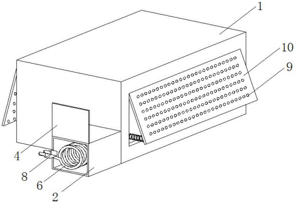
Figure 202021137638

The utility model discloses a charger with a battery overheating protection function, which relates to the field of charger equipment. A motor is installed inside the charger main body, and a temperature sensor is installed on the inner wall of the charger main body. The utility model is provided with a temperature sensor, a motor, a connecting rope, a heat dissipation plate and a second spring, the temperature sensor detects the temperature inside the main body of the charger, the PLC controller controls the operation of the motor, the motor drives the winding roller and the connecting rope to rotate, and the connection When the rope rotates, it stretches to the outside, and the heat dissipation plate drives the connecting rope to rotate to the outside under the elastic force of the second spring, so that the heat dissipation groove is exposed, and the two sides of the main body of the charger are opened, so that the external airflow can quickly enter the charger. Inside the main body, efficient heat dissipation is carried out, which effectively solves the problem of efficient heat dissipation of the charger.

Figure 202021137638

Description

Charger with storage battery overheating protection function
Technical Field
The utility model relates to a charger equipment field specifically is a charger with battery overheat protection function.
Background
The charger adopts a high-frequency power supply technology, applies an advanced intelligent dynamic adjustment charging technology, the power frequency machine is designed by the traditional analog circuit principle, the internal electric devices (such as a transformer, an inductor, a capacitor and the like) of the machine are large, and small noise exists in the general operation with large load, but the machine type has stronger resistance performance in severe power grid environment conditions, and the reliability and the stability are stronger than those of the high-frequency machine.
Current charger can produce the high temperature after charging a period, especially in summer, lasts the high temperature and can cause the charger to damage, and life reduces, so need carry out high-efficient heat dissipation to the charger and handle, and the charging wire of current charger does not have storage device, leads to the charging wire to place at will, destroys easily.
SUMMERY OF THE UTILITY MODEL
The utility model aims to provide a: in order to solve the problems of high-efficiency heat dissipation and storage of charging wires of the charger, the charger with the storage battery overheating protection function is provided.
In order to achieve the above object, the utility model provides a following technical scheme: the utility model provides a charger with battery overheat protection function, includes the charger main part, the one end of charger main part is provided with the protection box, and the inboard of charger main part is provided with the radiating groove, the internally mounted of charger main part has the motor, and the inner wall of charger main part installs temperature sensor, the inside of protection box is provided with first spring, one side of first spring is provided with the charging wire, be provided with the buckle on the charging wire, and the one end of charging wire is connected with the plug, the output of motor is provided with the winding roller, and one side of motor is provided with the supporting shoe, be provided with the connection rope on the winding roller, one side that the motor was kept away from to the supporting shoe is connected with the second spring, one side that the supporting shoe was kept away from to.
Preferably, the top of protection box is connected with the lid, and lid and protection box pass through hinge rotation connection.
Preferably, the protection box is welded at one end of the charger main body, the heat dissipation plate is provided with heat dissipation holes, and the temperature sensor is electrically connected with the motor through a PLC (programmable logic controller).
Preferably, both sides of the charger main body are provided with heat dissipation grooves, and the heat dissipation plates are rotatably connected with the charger main body through rotating shafts.
Preferably, the connecting rope is fixedly connected with the heat dissipation plate through a connecting buckle, and a mounting seat is arranged at the bottom end of the motor.
Preferably, the second spring is welded on one side of the supporting block, and a through hole matched with the connecting rope is formed in the charger main body.
Preferably, the first spring and the charging wire are fixedly connected through buckles, and the number of the buckles is multiple.
Compared with the prior art, the beneficial effects of the utility model are that:
1. the utility model discloses a set up temperature sensor, including a motor, an end cap, a controller, and a cover plate, connect the rope, the heating panel, the second spring, temperature sensor detects the inside temperature of charger main part, PLC controller control motor operation, the motor drives the winding roller and is connected the rope and rotate, it extends to the outside when rotating to connect the rope, the heating panel drives under the elasticity of second spring and connects the rope and rotate to the outside, make the radiating groove exposed, and the both sides of charger main part are opened, can make outside air current get into the inside of charger main part fast, carry out high-efficient heat dissipation, the high-efficient radiating problem of charger has effectively been solved.
2. The utility model discloses a set up the protection box, first spring, the charging wire, the buckle, rotate the lid to the top of protection box, the pulling plug, make the plug drive the charging wire to the outside removal, the charging wire is when removing, through the fixed of buckle, and it is tensile to drive first spring to the outside, then can insert the plug on the socket, when pulling out the plug, can loosen the plug, then the plug drives the charging wire and withdraws to the protection box automatically under the elasticity of first spring, can accomodate the charging wire, and easy operation, the problem of accomodating of charging wire has effectively been solved.
Drawings
Fig. 1 is a schematic structural view of the present invention;
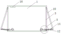
fig. 2 is a cross-sectional view of the present invention;
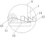
fig. 3 is an enlarged view of a of the present invention;
FIG. 4 is a schematic view of the protective case of the present invention;
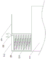
fig. 5 is the utility model discloses a charging wire schematic diagram.
In the figure: 1. a charger main body; 2. a protective case; 3. a heat sink; 4. a box cover; 5. a first spring; 6. a charging wire; 7. buckling; 8. a plug; 9. heat dissipation holes; 10. a heat dissipation plate; 11. a motor; 12. connecting ropes; 13. a support block; 14. a second spring; 15. a winding roller; 16. a temperature sensor.
Detailed Description
The technical solutions in the embodiments of the present invention will be described clearly and completely with reference to the accompanying drawings in the embodiments of the present invention, and it is obvious that the described embodiments are only some embodiments of the present invention, not all embodiments. Based on the embodiments in the present invention, all other embodiments obtained by a person skilled in the art without creative work belong to the protection scope of the present invention.
The motor (ZWBPD 024024024024-4) and the temperature sensor (Pt100) mentioned in the utility model can be obtained by market or private ordering.
Referring to fig. 1-5, a charger with a storage battery overheat protection function includes a charger main body 1, a protection box 2 is disposed at one end of the charger main body 1, a heat dissipation groove 3 is disposed on the inner side of the charger main body 1, a motor 11 is mounted inside the charger main body 1, a temperature sensor 16 is mounted on the inner wall of the charger main body 1, a first spring 5 is disposed inside the protection box 2, a charging wire 6 is disposed on one side of the first spring 5, a buckle 7 is disposed on the charging wire 6, one end of the charging wire 6 is connected with a plug 8, an output end of the motor 11 is provided with a winding roller 15, a support block 13 is disposed on one side of the motor 11, a connection rope 12 is disposed on the winding roller 15, a second spring 14 is connected to one side of the support block 13 far away from the motor 11, and a heat dissipation plate 10.
Please refer to fig. 1 heavily, the top end of the protection box 2 is connected with the box cover 4, the box cover 4 protects and seals the protection box 2, the box cover 4 is rotatably connected with the protection box 2 through a hinge, the box cover 4 is convenient to rotate, the protection box 2 is opened, the protection box 2 is welded at one end of the charger main body 1, the protection box 2 is convenient to be fixed at one end of the charger main body 1, a heat dissipation hole 9 is formed in a heat dissipation plate 10, the heat dissipation hole 9 is used for slight heat dissipation of the charger main body 1, the temperature sensor 16 is electrically connected with the motor 11 through a PLC controller, the temperature sensor 16 detects the temperature inside the charger main body 1, the detected temperature signal is converted into an electric signal and is transmitted to the PLC controller, and the PLC.
Please refer to fig. 3 and fig. 3, the two sides of the charger main body 1 are both provided with heat dissipation grooves 3, which facilitate external air flow to enter the charger main body 1 from the two sides, so as to accelerate the heat dissipation rate, the heat dissipation plate 10 is rotatably connected with the charger main body 1 through a rotating shaft, so as to facilitate the rotation of the heat dissipation plate 10, the connection rope 12 is fixedly connected with the heat dissipation plate 10 through a connection buckle, so as to facilitate the fixing of one end of the connection rope 12 on the heat dissipation plate 10, so as to drive the heat dissipation plate 10 to rotate, and the bottom end of the motor 11 is provided with a mounting seat, which fixes and supports the motor 11, the second spring 14 is welded on one side of the support block 13, so as to facilitate the fixing of the second spring 14 on the support block 13, and the charger main body 1.
Please refer to fig. 5, the first spring 5 is fixedly connected to the charging wire 6 through the plurality of fasteners 7, so that the charging wire 6 is conveniently fixed on one side of the first spring 5, the number of the fasteners 7 is plural, and the plurality of fasteners 7 fix the first spring 5 and the charging wire 6 with a certain length.
The working principle is as follows: when the utility model is used, the box cover 4 is rotated to the top end of the protection box 2, the plug 8 is pulled to enable the plug 8 to drive the charging wire 6 to move outwards, the charging wire 6 is fixed by the buckle 7 to drive the first spring 5 to stretch outwards when moving, the plug 8 can be inserted on a socket, when the plug 8 is pulled down, the plug 8 can be loosened, the plug 8 drives the charging wire 6 to automatically retract into the protection box 2 under the elasticity of the first spring 5, the charging wire 6 can be accommodated, the operation is simple, after the charger main body 1 is used for a period of time, the temperature sensor 16 detects the temperature inside the charger main body 1, the detected temperature signal is converted into an electric signal to be transmitted to the PLC controller, if the temperature exceeds a preset value, the PLC controller controls the motor 11 to operate, the motor 11 drives the winding roller 15 to rotate, thereby the winding roller 15 drives the connecting rope 12 to rotate, when the connection rope 12 is extended outward when rotating, the heat dissipation plate 10 drives the connection rope 12 to rotate outward under the elastic force of the second spring 14, so that the heat dissipation groove 3 is exposed, and the two sides of the charger main body 1 are opened, so that the external air flow can rapidly enter the inside of the charger main body 1 to perform efficient heat dissipation.
It is obvious to a person skilled in the art that the invention is not restricted to details of the above-described exemplary embodiments, but that it can be implemented in other specific forms without departing from the spirit or essential characteristics of the invention. The present embodiments are therefore to be considered in all respects as illustrative and not restrictive, the scope of the invention being indicated by the appended claims rather than by the foregoing description, and all changes which come within the meaning and range of equivalency of the claims are therefore intended to be embraced therein. Any reference sign in a claim should not be construed as limiting the claim concerned.

Claims (7)

1. A charger with a function of protecting a storage battery from overheating includes a charger main body (1), characterized in that: one end of the charger main body (1) is provided with a protection box (2), the inner side of the charger main body (1) is provided with a heat dissipation groove (3), the charger main body (1) is internally provided with a motor (11), the inner wall of the charger main body (1) is provided with a temperature sensor (16), the protection box (2) is internally provided with a first spring (5), one side of the first spring (5) is provided with a charging wire (6), the charging wire (6) is provided with a buckle (7), one end of the charging wire (6) is connected with a plug (8), the output end of the motor (11) is provided with a winding roller (15), one side of the motor (11) is provided with a supporting block (13), the winding roller (15) is provided with a connecting rope (12), one side of the supporting block (13) far away from the motor (11) is connected with a second spring (14), and a heat dissipation plate (10) is arranged on one side, away from the supporting block (13), of the second spring (14).
2. The charger with a battery overheat protection function according to claim 1, wherein: the top of protection box (2) is connected with lid (4), and lid (4) and protection box (2) are connected through the hinge rotation.
3. The charger with a battery overheat protection function according to claim 1, wherein: the protection box (2) is welded at one end of the charger main body (1), the heat dissipation plate (10) is provided with the heat dissipation holes (9), and the temperature sensor (16) is electrically connected with the motor (11) through the PLC.
4. The charger with a battery overheat protection function according to claim 1, wherein: the charger is characterized in that heat dissipation grooves (3) are formed in two sides of the charger main body (1), and the heat dissipation plates (10) are rotatably connected with the charger main body (1) through rotating shafts.
5. The charger with a battery overheat protection function according to claim 1, wherein: the connecting rope (12) is fixedly connected with the heat dissipation plate (10) through a connecting buckle, and the bottom end of the motor (11) is provided with a mounting seat.
6. The charger with a battery overheat protection function according to claim 1, wherein: the second spring (14) is welded on one side of the supporting block (13), and a through hole matched with the connecting rope (12) is formed in the charger main body (1).
7. The charger with a battery overheat protection function according to claim 1, wherein: first spring (5) pass through buckle (7) fixed connection with charging wire (6), and the quantity of buckle (7) is a plurality of.
CN202021137638.7U 2020-06-18 2020-06-18 A charger with battery overheating protection function Active CN212304812U (en)

Priority Applications (1)

Application Number Priority Date Filing Date Title
CN202021137638.7U CN212304812U (en) 2020-06-18 2020-06-18 A charger with battery overheating protection function

Applications Claiming Priority (1)

Application Number Priority Date Filing Date Title
CN202021137638.7U CN212304812U (en) 2020-06-18 2020-06-18 A charger with battery overheating protection function

Publications (1)

Publication Number Publication Date
CN212304812U true CN212304812U (en) 2021-01-05

Family

ID=73941804

Family Applications (1)

Application Number Title Priority Date Filing Date
CN202021137638.7U Active CN212304812U (en) 2020-06-18 2020-06-18 A charger with battery overheating protection function

Country Status (1)

Country Link
CN (1) CN212304812U (en)

Cited By (2)

* Cited by examiner, † Cited by third party
Publication number Priority date Publication date Assignee Title
CN113488822A (en) * 2021-07-12 2021-10-08 赣州市瑞嘉达电子有限公司 Auxiliary storage equipment for power adapter
CN113570770A (en) * 2021-08-11 2021-10-29 江西志宏安防科技有限公司 Intelligent security access control system based on voice recognition

Similar Documents

Publication Publication Date Title
CN204030518U (en) The intelligent vent flap of a kind of cable duct of substation
CN211151119U (en) Automatic temperature and humidity control device of power distribution cabinet
CN210838508U (en) An electrical cabinet with heat dissipation and dehumidification function
CN109779936B (en) But floor fan of automatically regulated height
CN207664787U (en) A kind of motor that intelligent overheat cools down automatically
CN110829245A (en) An automatic control cooling cooling type on-site cabinet
CN214674684U (en) High heat dissipation variable frequency speed control motor rotor structure
CN211981330U (en) A power distribution box with good heat dissipation effect
CN105552812A (en) Power line fixing rack with high convenience
CN210016408U (en) Inversion cabinet for inverter
CN209744929U (en) An outdoor drying device for plywood
WO2022099863A1 (en) Baking apparatus for wire and cable production
CN219107314U (en) Photovoltaic grid-connected inverter
CN221668907U (en) A portable lithium battery energy storage device
CN216122234U (en) High-efficient radiating solar inverter
CN206442227U (en) An energy-saving variable frequency motor
CN205429659U (en) Power line mount that convenience is high
CN221687603U (en) A heat dissipation device for photovoltaic power generation and energy storage
CN212626563U (en) High reliability watertight fittings for metal machine case
CN109194154B (en) Inverter parallel control method and inverter
CN207069621U (en) A kind of consumer unit
CN221900836U (en) A photovoltaic power transformer junction box
CN209233768U (en) A kind of energy conservation electrical storage type distributed new generating equipment
CN222953762U (en) A battery charger for direct charging of photovoltaic modules
CN222509257U (en) Burn-out prevention junction box in photovoltaic power generation system

Legal Events

Date Code Title Description
GR01 Patent grant
GR01 Patent grant
PP01 Preservation of patent right

Effective date of registration: 20210517

Granted publication date: 20210105

PD01 Discharge of preservation of patent

Date of cancellation: 20240517

Granted publication date: 20210105

TR01 Transfer of patent right

Effective date of registration: 20250228

Address after: 226400 north side of Huanghe Road, new economic development zone, Rudong County, Nantong City, Jiangsu Province

Patentee after: Nantong Wanze Metal Materials Co.,Ltd.

Country or region after: China

Address before: No. D702 and d703, 7th floor, building D, Huafeng International Robot Industrial Park, Hangcheng Avenue, Nanchang community, Xixiang street, Bao'an District, Shenzhen, Guangdong 518000

Patentee before: Shenzhen Jinyuan Chenghui Technology Co.,Ltd.

Country or region before: China