CN212299274U - Heat radiator for computer communication computer lab - Google Patents
Heat radiator for computer communication computer lab Download PDFInfo
- Publication number
- CN212299274U CN212299274U CN202020639413.5U CN202020639413U CN212299274U CN 212299274 U CN212299274 U CN 212299274U CN 202020639413 U CN202020639413 U CN 202020639413U CN 212299274 U CN212299274 U CN 212299274U
- Authority
- CN
- China
- Prior art keywords
- shell layer
- inner shell
- computer communication
- computer lab
- outer shell
- Prior art date
- Legal status (The legal status is an assumption and is not a legal conclusion. Google has not performed a legal analysis and makes no representation as to the accuracy of the status listed.)
- Expired - Fee Related
Links
Images


Landscapes
- Cooling Or The Like Of Electrical Apparatus (AREA)
Abstract
The utility model discloses a heat abstractor of computer communication computer lab, including computer lab, setting at the storage water tank at computer lab top and install the refrigerator at the computer lab side, the computer lab is including the inner shell layer that is used for placing the rack and the outer shell layer that is located the inner shell layer outside, be equipped with the chamber way between inner shell layer and the outer shell layer, be equipped with circulating line in the chamber way, circulating line's one end and one side intercommunication of storage water tank, circulating line's the other end and the other end intercommunication of storage water tank, the last circulating pump that is equipped with of circulating line, the air conditioning exit end of refrigerant is connected with the cold air duct, outer shell layer and inner shell layer intercommunication are passed to the one end of cold air duct, be equipped with the air outlet. The utility model discloses a heat that storage water tank, circulating pump and circulating line produced in to the computer lab absorbs, has realized the quick heat dissipation of computer lab, and the radiating effect is good, has protected the components and parts in the computer lab effectively.
Description
Technical Field
The utility model relates to a heat dissipation equipment field especially relates to a heat abstractor of computer communication computer lab.
Background
Information equipment rooms such as data center rooms and core rooms are important places for placing communication electronic equipment. With the rapid development of industries such as global communication, internet of things, electronic commerce, cloud computing and the like, a large number of electronic information rooms are built for communication operators, governments, enterprises and the like. Along with the long-term work of equipment, the heat in the computer lab can rise rapidly, especially when the weather is sultry, if not in time handle the heat, often can the accident appear, cause the loss that can not compensate.
Chinese patent No. CN 208282342U's utility model discloses a heat abstractor of computer communication computer lab, its air intake that adopts the wind direction alignment communication equipment that sweeps of constant temperature machine air outlet, the wind that sweeps of rational utilization constant temperature machine air outlet, to communication equipment's display card, memory and components that generate heat such as CPU treater adopt forced convection to carry out radiating mode, avoid forming local hot spot region, but such heat abstractor radiating effect is not good, can't reduce the temperature in the computer lab fast, cause inside temperature to rise easily, make components and parts receive the damage.
SUMMERY OF THE UTILITY MODEL
In order to overcome the defects existing in the prior art, the utility model provides a heat radiator for computer communication machine room.
The utility model provides a technical scheme that its technical problem adopted is: the utility model provides a heat abstractor of computer communication computer lab, includes the computer lab, sets up the storage water tank at the computer lab top and installs the refrigerator at the computer lab side, the computer lab is including the inner shell layer that is used for placing the rack and the outer shell layer that is located the inner shell layer outside, be equipped with the chamber between inner shell layer and the outer shell layer and say, be equipped with the circulating line in the chamber, the one end of circulating line and one side intercommunication of storage water tank, the other end of circulating line and the other end intercommunication of storage water tank, the last circulating pump that is equipped with of circulating line, the air conditioning exit end of refrigerant is connected with the cold air duct, outer shell layer and inner shell layer intercommunication are passed to the one end of cold air duct.
In one embodiment, a fan is fixed to an upper inner wall of the inner shell.
In one embodiment, a filter screen is arranged in the air outlet.
In one embodiment, the inner wall of the outer shell layer is provided with a heat absorption block, and the cross section of the heat absorption block is triangular.
In one embodiment, the outer surface of the inner shell is provided with a locking assembly for fixing the circulation pipe.
In one embodiment, the locking assembly comprises a mounting seat, a fixing rope, a plug connector and a socket connector, wherein the mounting seat and the socket connector are fixed on the outer surface of the outer shell layer, the socket connector is located on the side edge of the mounting seat, one end of the fixing rope is connected with the mounting seat, and the other end of the fixing rope is connected with the plug connector matched with the socket connector.
In one embodiment, the outer surface of the outer shell is connected with a supporting plate, the refrigerating machine is fixed on the upper surface of the supporting plate, the lower surface of the supporting plate is connected with a reinforcing strip which is obliquely arranged, and the other end of the reinforcing strip is connected with the outer surface of the outer shell.
In one embodiment, the other end of the supporting plate is hinged with a fixing rod for clamping the refrigerator.
In one embodiment, the front surfaces of the outer shell layer and the inner shell layer are provided with communicated openings, and the openings are provided with bin gates.
Compared with the prior art, the beneficial effects of the utility model are that: when the computer lab carries out high-speed operation and produces the heat, the circulating pump starts to let in the cold water in the storage water tank and circulates in the circulating line and flow, make the cold water that enters into in the circulating line absorb the heat that produces in the computer lab fast, then get back to in the storage water tank and carry out the heat exchange with the cold water in the storage water tank through the rivers that the circulating line will absorb the heat again, and the refrigerator rethread cold air pipe lets in air conditioning to the inner shell layer, make air conditioning exchange at inner shell layer circulation flow and heat, the heat after the exchange is again through air outlet discharge to the external world, the quick heat dissipation of computer lab has been realized, the radiating effect is good, the components and parts in the computer lab.
Drawings
The present invention will be further explained with reference to the drawings and examples.
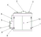
Fig. 1 is a schematic diagram of the heat dissipation device of the computer communication room of the present invention.
Fig. 2 is an internal schematic view of the heat dissipation device of the computer communication room of the present invention.
Figure 3 is a schematic view of the locking assembly.
Fig. 4 is a schematic view showing the connection of the support plate, the reinforcing bar and the fixing bar.
1-a machine room; 101-an outer shell layer; 102-an inner shell layer; 2-a water storage tank; 3-a circulation pipeline; 4-a circulating pump; 5-a refrigerator; 6-cold air pipe; 7-fixing the rod; 8-a support plate; 9-reinforcing bars; 10-bin gate; 11-lumen; 12-an air outlet; 13-a filter screen; 14-a heat sink block; 15-a locking assembly; 151-mounting base; 152-a securing cord; 153-plug-in unit; 154-a socket; 16-Fan.
Detailed Description
The present invention will now be described in further detail with reference to the accompanying drawings. These drawings are simplified schematic drawings and illustrate the basic structure of the present invention only in a schematic manner, and thus show only the components related to the present invention.
Example 1
Referring to fig. 1-4, a heat dissipation device for a computer communication room comprises a room 1, a water storage tank 2 disposed at the top of the room 1, and a refrigerator 5 installed at the side of the room 1, wherein the room 1 comprises an inner shell 102 for placing a cabinet and an outer shell 101 disposed at the outer side of the inner shell 102, a cavity 11 is disposed between the inner shell 102 and the outer shell 101, a circulation pipe 3 is disposed in the cavity 11, one end of the circulation pipe 3 is communicated with one side of the water storage tank 2, the other end of the circulation pipe 3 is communicated with the other end of the water storage tank 2, a circulation pump 4 is disposed on the circulation pipe 3, a cold air outlet end of the refrigerant 5 is connected with a cold air pipe 6, one end of the cold air pipe 6 passes through the outer shell 101 to be communicated with the inner shell 102, an air outlet 12 communicated with the inner shell 102 is disposed on the outer shell 101, and openings communicated with the front surfaces of the outer, the opening is provided with a bin gate 10.
The embodiment of the utility model provides an in, open door 10 and put into inner shell layer 102 the inside to the rack, when computer lab 1 carries out high-speed operation and produces the heat, circulating pump 4 starts to let in the cold water in the storage water tank 2 and circulates in circulating line 3 and flow, make the cold water that enters into in the circulating line 3 absorb the heat that produces in the computer lab 1 fast, then get back to the storage water tank 2 through circulating line 4 with the rivers that absorb the heat and carry out the heat exchange with the cold water in the storage water tank 2, and refrigerator 5 rethread trachea 6 lets in inner shell layer 102 with air conditioning, shell layer 102 circulation flow exchanges with the heat including air conditioning, the heat after the exchange is again through air outlet 12 discharges to the external world, the quick heat dissipation of computer lab 1 has been realized, the radiating effect is good, the components and parts in the computer lab 1 have been protected effectively to.
In one embodiment, in order to accelerate the exchange between the cool air and the heat in the machine room 1 and further improve the heat dissipation effect of the machine room 1, in this embodiment, a fan 16 is fixed on the upper inner wall of the inner shell 102, the fan 16 blows the cool air entering the inner shell 102 to circulate, so that the heat is rapidly exchanged, and then the exchanged heat is exhausted to the outside through the air outlet 12.
In one embodiment, in order to prevent external dust or impurities from entering the machine room 1 from the air outlet 12, in the present embodiment, a filter screen 13 is disposed in the air outlet 12.
In an embodiment, in order to further accelerate heat dissipation in the machine room 1, in this embodiment, the inner wall of the outer shell 101 is provided with the heat absorption block 14, and a cross section of the heat absorption block 14 is triangular, so that heat of the inner shell 102 is conducted into the cavity 11, and then the heat absorption block 14 located in the cavity can quickly dissipate the heat, thereby further improving the heat dissipation effect of the machine room 1.
In one embodiment, the outer surface of the inner shell 102 is provided with a locking assembly 15 for fixing the circulation pipe 3, the locking assembly 15 includes a mounting seat 151, a fixing rope 152, a plug connector 153 and a plug connector 154, the mounting seat 151 and the plug connector 154 are both fixed on the outer surface of the outer shell 101, the plug connector 154 is located at a side of the mounting seat 151, one end of the fixing rope 152 is connected with the mounting seat 151, and the other end of the fixing rope 152 is connected with the plug connector 153 matched with the plug connector 154.
When the circulating pipeline 3 is placed into the cavity 11, one end of the fixing rope 152 is connected to the mounting seat 151, and then the plug connector 153 connected to the other end of the fixing rope 152 is plugged into the plug connector 154, so that the circulating pipeline 3 is fixed on the outer surface of the inner shell layer 102 by the fixing rope 152, thereby increasing the contact between cold water in the circulating pipeline 3 and the inner shell layer, accelerating the exchange of heat and cold water, and realizing the rapid cooling of the machine room 1.
In one embodiment, a supporting plate 8 is connected to the outer surface of the casing layer 101, the refrigerator 5 is fixed on the upper surface of the supporting plate 8, a reinforcing strip 9 is connected to the lower surface of the supporting plate 8, the other end of the reinforcing strip 9 is connected to the outer surface of the casing layer 101, and a fixing rod 7 for clamping the refrigerator 5 is hinged to the other end of the supporting plate 8.
Strengthen the strip 9 through connecting the slope setting at the lower surface of backup pad 8 and can increase refrigerator 5's stability effectively, articulated dead lever 7 can carry out the chucking to refrigerator 5 simultaneously, avoids the during operation to appear rocking and causes and drop, also is convenient for dismantle refrigerator 5 get off and wash or maintain.
In the description herein, references to the description of the terms "one embodiment," "certain embodiments," "an illustrative embodiment," "an example," "a specific example," or "some examples," etc., mean that a particular feature, structure, material, or characteristic described in connection with the embodiment or example is included in at least one embodiment or example of the invention. In this specification, schematic representations of the above terms do not necessarily refer to the same embodiment or example. Furthermore, the particular features, structures, materials, or characteristics described may be combined in any suitable manner in any one or more embodiments or examples.
Furthermore, it should be noted that the terms "upper", "lower", "inner", "outer", etc. indicate orientations or positional relationships based on the orientations or positional relationships shown in the drawings, and are only for convenience of describing the present invention and simplifying the description, but do not indicate or imply that the indicated device or element must have a specific orientation, be constructed in a specific orientation, and be operated, and thus should not be construed as limiting the present invention; the terms "first," "second," and the like are used for descriptive purposes only and are not to be construed as indicating or implying relative importance; unless expressly stated or limited otherwise, the terms "mounted," "connected," and "connected" are intended to be inclusive and mean, for example, that they may be fixedly connected, detachably connected, or integrally connected; can be mechanically or electrically connected; they may be connected directly or indirectly through intervening media, or they may be interconnected between two elements. The specific meaning of the above terms in the present invention can be understood in specific cases to those skilled in the art.
Furthermore, it should be understood that although the present description refers to embodiments, not every embodiment may contain only a single embodiment, and such description is for clarity only, and those skilled in the art should integrate the description, and the embodiments may be combined as appropriate to form other embodiments understood by those skilled in the art.
Claims (9)
Priority Applications (1)
| Application Number | Priority Date | Filing Date | Title |
|---|---|---|---|
| CN202020639413.5U CN212299274U (en) | 2020-04-24 | 2020-04-24 | Heat radiator for computer communication computer lab |
Applications Claiming Priority (1)
| Application Number | Priority Date | Filing Date | Title |
|---|---|---|---|
| CN202020639413.5U CN212299274U (en) | 2020-04-24 | 2020-04-24 | Heat radiator for computer communication computer lab |
Publications (1)
| Publication Number | Publication Date |
|---|---|
| CN212299274U true CN212299274U (en) | 2021-01-05 |
Family
ID=73964326
Family Applications (1)
| Application Number | Title | Priority Date | Filing Date |
|---|---|---|---|
| CN202020639413.5U Expired - Fee Related CN212299274U (en) | 2020-04-24 | 2020-04-24 | Heat radiator for computer communication computer lab |
Country Status (1)
| Country | Link |
|---|---|
| CN (1) | CN212299274U (en) |
Cited By (1)
| Publication number | Priority date | Publication date | Assignee | Title |
|---|---|---|---|---|
| CN116669373A (en) * | 2023-04-23 | 2023-08-29 | 国网山西省电力公司信息通信分公司 | An adjustable cooling device for information and communication equipment room |
-
2020
- 2020-04-24 CN CN202020639413.5U patent/CN212299274U/en not_active Expired - Fee Related
Cited By (1)
| Publication number | Priority date | Publication date | Assignee | Title |
|---|---|---|---|---|
| CN116669373A (en) * | 2023-04-23 | 2023-08-29 | 国网山西省电力公司信息通信分公司 | An adjustable cooling device for information and communication equipment room |
Similar Documents
| Publication | Publication Date | Title |
|---|---|---|
| JP3068892U (en) | CPU heat dissipation device | |
| CN207340352U (en) | A kind of air-conditioning electric control box | |
| CN204187747U (en) | Air conditioner | |
| TWI578887B (en) | Volume change heat dissipation system | |
| CN108227883A (en) | A kind of huge computer servers radiator | |
| CN113253808B (en) | Turbulent flow type bidirectional ventilation water-cooling computer mainframe box | |
| CN201418228Y (en) | Heat sink | |
| CN213399493U (en) | Heat radiation module in computer host case | |
| CN211267491U (en) | An integrated air source heat pump | |
| CN209960107U (en) | Novel heat dissipation box body for generator set | |
| CN222993131U (en) | Liquid cooling air conditioner heat radiation structure | |
| CN112074159B (en) | IT equipment heat dissipation cooling box | |
| CN105444293A (en) | Air conditioner | |
| CN206848926U (en) | A kind of Internet of things system server radiating cabinet | |
| CN223364201U (en) | An IoT switch with efficient heat dissipation | |
| CN212161192U (en) | An outdoor LED advertising machine | |
| CN222232967U (en) | Dual radiating computer radiator | |
| CN220752648U (en) | Computer cooling assembly | |
| CN222939439U (en) | Cold water heat radiation module installed between computer main board and hard disk | |
| CN221827287U (en) | Liquid cooling heat dissipation structure for high-performance computer | |
| CN222017077U (en) | Built-in heat radiation structure of vehicle-mounted navigator | |
| CN220254996U (en) | Liquid-cooled heat dissipation modularization cabinet | |
| CN222506866U (en) | Computer heat dissipation cooling device | |
| CN215599648U (en) | Computer equipment heat abstractor | |
| CN220235298U (en) | Computer network equipment with self-cooling function |
Legal Events
| Date | Code | Title | Description |
|---|---|---|---|
| GR01 | Patent grant | ||
| GR01 | Patent grant | ||
| CF01 | Termination of patent right due to non-payment of annual fee | ||
| CF01 | Termination of patent right due to non-payment of annual fee |
Granted publication date: 20210105 |