Sponge municipal sewage treatment system
Technical Field
The utility model belongs to the technical field of sewage treatment, concretely relates to sponge municipal sewage treatment system.
Background
Sewage treatment: in order to achieve the process of purifying sewage which is discharged into a certain water body or reused, the sewage treatment is widely applied to various fields of buildings, agriculture, traffic, energy, petrifaction, environmental protection, urban landscape, medical treatment, catering and the like, and the sewage treatment also increasingly enters the daily life of common people.
The existing sponge urban sewage treatment system has the defects of single filtering mode, poor filtering effect and difficulty in wide popularization and application.
SUMMERY OF THE UTILITY MODEL
The utility model aims at providing a sponge municipal sewage treatment system that filter effect is good to the above-mentioned problem that exists among the prior art.
In order to realize the purpose of the utility model, the utility model adopts the following technical scheme: a sponge urban sewage treatment system comprises a sludge settling chamber, a filter chamber communicated with the sludge settling chamber through a first water pipe, a sewage treatment chamber communicated with the filter chamber through a second water pipe, and a clean water chamber communicated with the sewage treatment chamber through a third water pipe; the sludge settling chamber is provided with a water inlet pipe arranged at the top of the sludge settling chamber, a plurality of settling tanks divided by a plurality of partition plates and a sludge discharge pipe arranged at the bottom of each settling tank; the filter chamber is provided with a filter screen plate and a garbage discharge pipe arranged at the bottom of the left side of the filter screen plate, and the second water pipe is arranged at the bottom of the right side of the filter screen plate; the sewage treatment chamber is provided with a suspended filler, a stirring device for stirring the suspended filler and sewage, an aeration device arranged at the bottom of the sewage treatment chamber and a filler adding pipe arranged at the top of the sewage treatment chamber; the clear water room is equipped with the ultraviolet ray disinfection lamp that is located clear water room inner wall top and at least part is located the indoor drain pipe of clear water, be equipped with the drain valve on the drain pipe.
The working principle is as follows: in sewage enters the sludge settling chamber from the water inlet pipe, sewage is settled in a first settling tank, water on the upper layer gradually stays in a second settling tank along with continuous entering of sewage, sludge is continuously accumulated at the bottom of the settling tank, clear water on the upper layer continuously flows to a next settling tank, the sludge can be discharged and centrally treated through the sludge discharge pipe, and finally flows into the filter chamber through the first water pipe, the filter chamber can filter garbage which is relatively large in particle size and can float on water, the garbage is finally cleaned through the garbage discharge pipe, the water filtered by the filter screen plate enters the sewage treatment chamber from the second water pipe, the suspended filler in the sewage treatment chamber can perform reaction treatment on the sewage, a large number of flora are arranged on the suspended filler, and the mixing degree of the sewage and the suspended filler is further improved by opening the stirring device and the aeration device, the sewage treatment efficiency is improved, the treated sewage can enter the clear water chamber from the third water pipe, the ultraviolet disinfection lamp in the clear water chamber continuously disinfects the clear water chamber, and finally the drain valve is opened to discharge the treated clear water through the drain pipe, so that the filtering effect is good, the energy is saved, a large amount of chemical agents are not needed, and the cost is saved; the suspended filler in the sewage treatment chamber can be conveniently supplemented through the filler adding pipe, and the sewage treatment effect is improved.
Further, the heights of the partition boards are sequentially reduced, and the number of the partition boards is at least two. The sludge settling chamber is divided into at least three settling tanks by the at least two partition plates, and as sewage is continuously introduced into the first settling tank, most of the sludge can be effectively settled only by the second settling tank, so that the at least three settling tanks can effectively settle most of the sludge, the sludge settling amount in subsequent sewage treatment is reduced, and the treatment difficulty of the subsequent sewage treatment can also be reduced; and the baffle from left to right reduces in proper order and can effectively prevent the sewage refluence.
Furthermore, a sludge stirring mechanism is arranged on the sludge discharge pipe, and the sedimentation tank is provided with a slope inclining towards the sludge discharge pipe. Mud rabbling mechanism has the (mixing) shaft rotation of stirring piece for common agitator motor drive, then stirs through stirring piece mud, prevents that mud from condensing on the sludge discharge pipe for the unable smooth discharge mud of sludge discharge pipe, the setting on slope can utilize the action of gravity to discharge mud better simultaneously.
Furthermore, a sludge collection chamber communicated with a sludge discharge pipe is arranged below the sludge settling chamber, the sludge collection chamber is provided with a first sealing door which can be turned over, and the sludge discharge pipe is provided with a sludge valve. Sludge is collected uniformly through the sludge collection chamber, so that uniform treatment is facilitated; the sludge discharge pipe opens a sludge valve when sludge needs to be discharged, and can also suck the sludge through a common sludge pump.
Furthermore, the filter chamber is provided with a garbage cleaning device which is positioned on the left side of the filter screen plate, the garbage cleaning device comprises a waterproof linear module which is arranged in parallel with the filter screen plate and a cleaning block which is arranged on the waterproof linear module, and sharp corners are arranged at the upper end and the lower end of the cleaning block. In order to prevent that partial rubbish from gluing on filtering the otter board, cause the filter effect of filtering the otter board to reduce, consequently come the drive through current waterproof system line module to install the washing piece on waterproof sharp line module slider and slide from top to bottom, scrape down the rubbish of adhering to on filtering the otter board through the closed angle of washing piece, clean effectual.
Furthermore, a garbage collection chamber communicated with a garbage discharge pipe is arranged below the filtering chamber, and the garbage collection chamber is provided with a second sealing door capable of being turned over. The garbage collection room can hold rubbish through the rubbish discharge pipe to collect the processing through the second is closed the door and is unified, prevents that rubbish from piling up in a large number at the filter chamber.
Furthermore, a filler filtering screen is arranged in the sewage treatment chamber and is arranged at the pipe orifice of the third water pipe. In order to reduce the loss of the suspended filler, the suspended filler is prevented from running out of the third water pipe by arranging the suspended filler outside the third water pipe through a filler filter screen cover.
Furthermore, the sewage treatment chamber is provided with a third reversible sealing door. Through the third closed door, the maintenance operation and the maintenance operation in the sewage treatment chamber can be conveniently carried out, and meanwhile, the suspended filler is recycled.
Furthermore, be equipped with water stain clearing device in second water pipe and the third water pipe, water stain clearing device is including the spring of locating second water pipe or third water pipe inner wall and connecting a plurality of water balls that keep off on the spring. In order to reduce the water stain of second water pipe and the long-time accumulation of third water pipe inner wall, cause the water pipe ageing, it can conveniently know the water stain through the clear device of water stain, when rivers lead to the water pipe, water can constantly strike spring and manger plate ball, make the spring constantly at water pipe inner wall concertina movement, thereby make the spring can not realize the function of knowing the water stain to ground friction water pipe inner wall, the manger plate ball not only can increase the area of contact who increases spring and water, but also can make the holistic inertia of increase spring, make the stroke that the spring can rock longer, clean effect is better.
Further, the spring is made of stainless steel. The spring made of stainless steel can effectively improve the corrosion resistance and the rust resistance of the spring, and the surface of the spring can be subjected to oxidation treatment to improve the corrosion resistance and the rust resistance of the spring.
Compared with the prior art, the sponge municipal sewage treatment system adopting the technical scheme has the following beneficial effects:
the utility model discloses a sponge municipal sewage treatment system has following advantage:
1: the suspended filler in the sewage treatment chamber can be conveniently supplemented through the filler adding pipe, and the sewage treatment effect is improved.
2: through mud deposit room, filter chamber, sewage treatment room and clear water room to carry out mud deposit, impurity filtration, sewage treatment and disinfection operation to water, the filter effect is good, and the energy can be saved need not to use a large amount of chemical agents, saves the cost.
Drawings
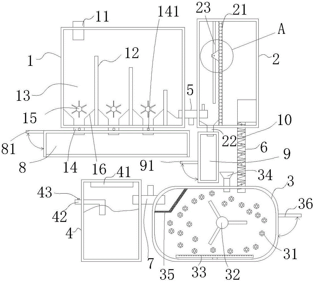
Fig. 1 is a first schematic structural diagram of the present invention;
FIG. 2 is a second schematic structural diagram of the present invention;
fig. 3 is an enlarged view of a in fig. 1.
In the figure, 1, a sludge settling chamber; 2. a filtering chamber; 3. a sewage treatment chamber; 4. a clear water chamber; 5. a first water pipe; 6. a second water pipe; 7. a third water pipe; 11. a water inlet pipe; 12. a partition plate; 13. a settling tank; 14. a sludge discharge pipe; 21. a filter screen plate; 22. a waste discharge pipe; 31. suspending the filler; 32. a stirring device; 33. an aeration device; 34. a filler addition tube; 41. an ultraviolet disinfection lamp; 42. a drain pipe; 43. a drain valve; 15. a sludge stirring mechanism; 16. a slope; 8. a sludge collection chamber; 81. a first closure door; 141. a sludge valve; 23. a garbage cleaning device; 231. a waterproof linear module; 232. cleaning the block; 9. a waste collection chamber; 91. a second closure door; 35. a filler filtering net cover; 36. a third sealing door; 10. a water stain removing device; 101. a spring; 102. a water blocking ball.
Detailed Description
The following are specific embodiments of the present invention and the accompanying drawings are used to further describe the technical solution of the present invention, but the present invention is not limited to these embodiments.
As shown in fig. 1-3, the sponge municipal sewage treatment system comprises a sludge settling chamber 1 made of stainless steel or poured with cement, a filtering chamber 2 made of stainless steel or poured with cement and communicated with a first water pipe 5 communicated with the sludge settling chamber 1, a sewage treatment chamber 3 made of stainless steel and communicated with the filtering chamber 2 through a second water pipe 6, and a clean water chamber 4 made of stainless steel or poured with cement and communicated with the sewage treatment chamber 3 through a third water pipe 7; wherein, the first water pipe 5, the second water pipe 6 and the third water pipe 7 are all water pipes made of common stainless steel or plastic, and the flowing capacity of sewage can be increased by connecting a water pump.
The sludge settling chamber 1 is provided with a water inlet pipe 11 welded or poured on the top of the sludge settling chamber 1 through cement, a plurality of settling tanks 13 divided by a plurality of partition plates 12 made of plastics or poured by cement and a sludge discharge pipe 14 arranged at the bottom of each settling tank 13, in the embodiment, the number of the partition plates 12 is three, the number of the settling tanks 13 is four, the sludge discharge pipe 14 is welded or poured on the bottom of the settling tank 13 through cement, the bottom of the settling tank 13 is also provided with a sludge stirring mechanism 15, the settling tank 13 is provided with a slope 16 inclined towards the sludge discharge pipe 14, wherein the sludge stirring mechanism 15 is a common stirring motor for driving a stirring shaft with stirring blades to rotate, and then the sludge is stirred through the stirring blades;
the filter chamber 2 is provided with a common microporous filter screen plate 21 and a garbage discharge pipe 22 arranged at the bottom of the left side of the filter screen plate 21, the garbage discharge pipe 22 is welded or poured at the bottom of the filter chamber 2 through cement, and the second water pipe 6 is welded or poured at the bottom of the right side of the filter screen plate 21 through cement;
the sewage treatment chamber 3 is provided with a commercially available suspended filler 31, a common stirring device 32 for stirring the suspended filler 31 and sewage, an aeration device 33 welded at the bottom of the sewage treatment chamber 3 and a filler adding pipe 34 welded at the top of the sewage treatment chamber 3, wherein the stirring device 32 and the front sludge stirring mechanism 15 have basically the same structure, the stirring motor is arranged on the outer wall of the sewage treatment chamber 3, the aeration device 33 is the common existing sewage aeration device 33, and the details are not repeated;
in this embodiment, the inner surface of the sewage treatment chamber 3 is rounded to prevent the floating packing 31 from being accumulated in the corner.
In this embodiment, the suspension packing 31 is a spherical suspension packing 31, also called a porous rotary spherical suspension packing 31, and the packing series is formed by injection molding of polypropylene material, and is divided into an inner layer sphere and an outer layer sphere, the outer layer is a hollow fishnet sphere, and the inner layer is a rotary sphere. The biological membrane carrier has the functions of a biological membrane carrier, also has the function of intercepting suspended matters, has the characteristics of strong biological adhesive force, large specific surface area, high porosity, good chemical and biological stability, durability, no harmful substances dissolved out, no secondary pollution, ultraviolet resistance, ageing resistance, strong hydrophilic performance and the like, and is easy to generate, easy to replace, resistant to acid and alkali, ageing resistant, free from water flow influence, long in service life, less in residual sludge and convenient to install in the using process.
The clean water chamber 4 is provided with a common commercially available high-power ultraviolet disinfection lamp 41 positioned at the top of the inner wall of the clean water chamber 4 and a drain pipe 42 welded or cement-poured on the clean water chamber 4, and the drain pipe 42 is provided with a common drain valve 43.
Preferably, sludge settling chamber 1 below is equipped with the mud collection chamber 8 that the panel beating of 14 intercommunications of sludge discharge pipes was bent the welding and is made, the mud collection chamber 8 side articulates there is first closed door 81, can take out mud through opening first closed door 81 and unify the processing, be equipped with sludge valve 141 on the sludge discharge pipes 14, sludge discharge pipes 14 can also be through connecting common sludge pump and absorbing mud better, and sludge valve 141 is common valve, no longer gives unnecessary details to its structure here.
Preferably, the filtering chamber 2 is provided with a garbage cleaning device 23 located at the left side of the filtering screen plate 21, the garbage cleaning device 23 comprises a commercially available waterproof linear module 231 arranged in parallel with the filtering screen plate 21 and a cleaning block 232 mounted on a sliding block of the waterproof linear module 231, the cleaning block 232 is made of stainless steel, the upper end and the lower end of the cleaning block 232 are provided with sharp corners, one surface of the cleaning block 232 is in contact with the filtering screen plate 21, the cleaning block 232 is driven by the waterproof linear module 231 to move up and down, and then the sharp corners can continuously scrape the filtering screen plate 21, so that the garbage cleaning operation on the surface of the filtering screen plate 21 is realized.
Preferably, a garbage collection chamber 9 communicated with the garbage discharge pipe 22 is provided under the filtering chamber 2, and the garbage collection chamber 9 is hinged with a second closing door 91, so that garbage can be conveniently taken out and disposed by opening the second closing door 91.
Preferably, be equipped with filler filter screen panel 35 that common fishing net made in the sewage treatment room 3, filler filter screen panel 35 passes through the lifting rope and installs in sewage treatment room 3, can effectively block suspension filler 31, and is with low costs moreover.
Preferably, the sewage treatment chamber 3 is hinged with a third sealing door 36, and the third sealing door 36 can be used for conveniently performing maintenance operation and maintenance operation in the sewage treatment chamber 3 and recovering the suspended filler 31.
Preferably, a water stain removing device 10 is arranged in the second water pipe 6 and the third water pipe 7, the water stain removing device 10 comprises a stainless steel spring 101 which is arranged on the inner wall of the two water pipes and a plurality of water blocking balls 102 which are welded or bound on the spring 101, and the water blocking balls 102 can be made of stainless steel or stone.
The specific embodiments described herein are merely illustrative of the spirit of the invention. Various modifications, additions and substitutions for the specific embodiments described herein may be made by those skilled in the art without departing from the spirit of the invention or exceeding the scope of the invention as defined in the accompanying claims.
Although the terms of the sludge settling chamber 1, the filtering chamber 2, the sewage treatment chamber 3, the clean water chamber 4, the first water pipe 5, the second water pipe 6, the third water pipe 7, the water inlet pipe 11, the partition plate 12, the settling tank 13, the sludge discharge pipe 14, the filtering mesh plate 21, the garbage discharge pipe 22, the suspended filler 31, the stirring device 32, the aeration device 33, the filler adding pipe 34, the ultraviolet disinfection lamp 41, the water discharge pipe 42, the water discharge valve 43, the sludge stirring mechanism 15, the slope 16, the sludge collection chamber 8, the first closing door 81, the sludge valve 141, the garbage cleaning device 23, the waterproof linear module 231, the cleaning block 232, the garbage collection chamber 9, the second closing door 91, the filler filtering mesh 35, the third closing door 36, the water stain removing device 10, the spring 101, the water blocking ball 102, and the like are used more herein, the possibility of using other terms is not excluded. These terms are used merely to more conveniently describe and explain the nature of the present invention; they are to be construed in a manner that is inconsistent with the spirit of the invention.