CN212288226U - Double-bubble method inflation film manufacturing machine compounding device - Google Patents
Double-bubble method inflation film manufacturing machine compounding device Download PDFInfo
- Publication number
- CN212288226U CN212288226U CN202020421152.XU CN202020421152U CN212288226U CN 212288226 U CN212288226 U CN 212288226U CN 202020421152 U CN202020421152 U CN 202020421152U CN 212288226 U CN212288226 U CN 212288226U
- Authority
- CN
- China
- Prior art keywords
- rotating shaft
- pivot
- box body
- box
- wall
- Prior art date
- Legal status (The legal status is an assumption and is not a legal conclusion. Google has not performed a legal analysis and makes no representation as to the accuracy of the status listed.)
- Expired - Fee Related
Links
- 238000000034 method Methods 0.000 title claims abstract description 9
- 238000013329 compounding Methods 0.000 title abstract description 17
- 238000004519 manufacturing process Methods 0.000 title abstract description 9
- 239000000463 material Substances 0.000 claims abstract description 33
- 238000002156 mixing Methods 0.000 claims abstract description 27
- 238000010096 film blowing Methods 0.000 claims description 13
- 244000309464 bull Species 0.000 claims description 4
- 238000003756 stirring Methods 0.000 abstract description 21
- 230000000694 effects Effects 0.000 abstract description 11
- 230000002337 anti-port Effects 0.000 abstract description 5
- 238000010586 diagram Methods 0.000 description 2
- 238000007580 dry-mixing Methods 0.000 description 2
- 239000000155 melt Substances 0.000 description 2
- 239000002245 particle Substances 0.000 description 2
- 239000002994 raw material Substances 0.000 description 2
- 230000001360 synchronised effect Effects 0.000 description 2
- 230000009286 beneficial effect Effects 0.000 description 1
- 238000007599 discharging Methods 0.000 description 1
Images
Landscapes
- Processing And Handling Of Plastics And Other Materials For Molding In General (AREA)
Abstract
The utility model provides a two bubble method inflation film manufacturing machine compounding device belongs to inflation film manufacturing machine technical field, be in including support and setting the box on support upper portion, the feed inlet has been seted up to the box upper wall, and the bin outlet has been seted up to box lateral wall below, the inside compounding subassembly that is provided with of box, the compounding subassembly includes the first pivot of vertical setting, sets up second pivot and the rotation setting of first pivot below are in first pivot with a plurality of actuating levers of second pivot lateral wall. The embodiment of the utility model provides an have even and the efficient advantage of compounding, through the antiport of first pivot and second pivot for the actuating lever of its lateral wall carries out circular motion, carries out horizontal stirring to the material, orders about the actuating lever rotation under drive assembly's effect simultaneously, and then drives the compounding pole and rotate, carries out vertical stirring to the material, combines the horizontal stirring of actuating lever, realizes the multi-direction stirring of material, improves the mixing effect of material.
Description
Technical Field
The utility model belongs to the technical field of inflation film manufacturing machine, specifically a two bubble method inflation film manufacturing machine compounding device.
Background
The film blowing machine heats and melts plastic particles and then blows the plastic particles into a film. Film blowing machines are divided into many types, including PE, POF, PVC, and the like.
Because the film has the variety, inflation film manufacturing machine during operation need mix various raw materials sometimes, melts the raw materials of misce bene to prepare different films, current inflation film manufacturing machine compounding device during operation with various materials drop into the compounding case, deuterogamy rabbling mechanism stirs, but current stirring subassembly stirring mode is comparatively single, thereby the compounding effect that leads to the material is relatively poor.
SUMMERY OF THE UTILITY MODEL
Not enough to above-mentioned prior art, the embodiment of the utility model provides a technical problem who solves provides a two bubble method inflation film manufacturing machines compounding device.
In order to solve the technical problem, the utility model provides a following technical scheme:
a mixing device of a double-bubble method film blowing machine comprises a support and a box body arranged on the upper portion of the support, wherein a feed inlet is formed in the upper wall of the box body, a discharge outlet is formed in the lower portion of the side wall of the box body, a mixing assembly is arranged in the box body and comprises a first rotating shaft which is vertically arranged, a second rotating shaft which is arranged below the first rotating shaft and a plurality of driving rods which are rotatably arranged on the side wall of the first rotating shaft and the second rotating shaft, a plurality of dry mixing rods are fixedly arranged on the outer wall of each driving rod group, the upper end of the first rotating shaft penetrates through the box body and is fixedly connected with a motor, a steering gear is arranged between the first rotating shaft and the second rotating shaft, a plurality of first tooth sheets which are annularly distributed are arranged on the bottom of the first rotating shaft and the upper portion of the second rotating shaft, the bottom of the second rotating shaft is rotatably matched with the bottom, the steering gear passes through the bracing piece with the box inner wall rotates to be connected, the box inner wall still is provided with and is used for driving actuating lever pivoted drive assembly.
As a further improvement of the utility model: the first rotating shaft is in running fit with the box body at the joint through a bearing.
As a further improvement of the utility model: the first rotating shaft and the side wall of the second rotating shaft are matched with the driving rod in a rotating mode through a first rotating rod.
As a further improvement of the utility model: the driving assembly comprises a supporting ring plate and second gear pieces, the supporting ring plate is circumferentially distributed on the inner wall of the box body, the second gear pieces are evenly arranged at the bottom of the supporting ring plate, the tail end of the driving rod is connected with a gear through a connecting rod, and the gear is meshed with the second gear pieces.
As a further improvement of the present invention: the upper portion of the support is hinged to a telescopic rod, and one end, far away from the support, of the telescopic rod is hinged to the side wall of the box body.
As a further improvement of the present invention: the telescopic rod is an electric telescopic rod or a hydraulic telescopic rod.
Compared with the prior art, the beneficial effects of the utility model are that:
the embodiment of the utility model provides an have even and the efficient advantage of compounding, through the antiport of first pivot and second pivot for the actuating lever of its lateral wall carries out circular motion, carries out horizontal stirring to the material, orders about the actuating lever rotation under drive assembly's effect simultaneously, and then drives the compounding pole and rotate, carries out vertical stirring to the material, combines the horizontal stirring of actuating lever, realizes the multi-direction stirring of material, improves the mixing effect of material.
Drawings
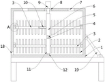
Fig. 1 is a schematic structural diagram of a mixing device of a double-bubble film blowing machine.
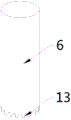
Fig. 2 is a schematic structural diagram of a first rotating shaft in a mixing device of a double bubble film blowing machine.
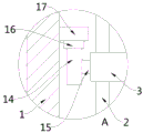
Fig. 3 is an enlarged schematic view of the area a in fig. 1.
In the figure: 1-box body, 2-mixing rod, 3-driving rod, 4-steering gear, 5-supporting rod, 6-first rotating shaft, 7-feeding hole, 8-bearing, 9-motor, 10-first rotating rod, 11-second rotating shaft, 12-second rotating rod, 13-first tooth sheet, 14-gear, 15-connecting rod, 16-second tooth sheet, 17-supporting ring plate, 18-discharging hole and 19-telescopic rod.
Detailed Description
The technical solution of the present patent will be described in further detail with reference to the following embodiments.
Reference will now be made in detail to embodiments of the present patent, examples of which are illustrated in the accompanying drawings, wherein like or similar reference numerals refer to the same or similar elements or elements having the same or similar function throughout. The embodiments described below with reference to the drawings are exemplary only for the purpose of explaining the present patent and are not to be construed as limiting the present patent.
In the description of this patent, it is to be understood that the terms "center," "upper," "lower," "front," "rear," "left," "right," "vertical," "horizontal," "top," "bottom," "inner," "outer," and the like are used in the orientations and positional relationships indicated in the drawings for the convenience of describing the patent and for the simplicity of description, and are not intended to indicate or imply that the referenced devices or elements must have a particular orientation, be constructed and operated in a particular orientation, and are not to be considered limiting of the patent.
In the description of this patent, it is noted that unless otherwise specifically stated or limited, the terms "mounted," "connected," and "disposed" are to be construed broadly and can include, for example, fixedly connected, disposed, detachably connected, disposed, or integrally connected and disposed. The specific meaning of the above terms in this patent may be understood by those of ordinary skill in the art as appropriate.
Example 1
Referring to fig. 1-3, the embodiment provides a mixing device for a double bubble method film blowing machine, which includes a bracket and a box body 1 disposed on the upper portion of the bracket, wherein a feed inlet 7 is disposed on the upper wall of the box body 1, a discharge outlet 18 is disposed below the side wall of the box body 1, a mixing assembly is disposed inside the box body 1, specifically, the mixing assembly includes a first rotating shaft 6 disposed vertically, a second rotating shaft 11 disposed below the first rotating shaft 6, and a plurality of driving rods 3 rotatably disposed on the side walls of the first rotating shaft 6 and the second rotating shaft 11, a plurality of dry mixing rods 2 are fixedly disposed on the outer wall of each driving rod 3, the upper end of the first rotating shaft 6 penetrates through the box body 1 and is fixedly connected with a motor 9, a steering gear 4 is disposed between the first rotating shaft 6 and the second rotating shaft 11, a plurality of first tooth plates 13 are disposed at the bottom of the first rotating shaft 6 and at the upper portion of, 11 bottoms of second pivot are through second bull stick 12 and box 1 bottom normal running fit, steering gear 4 with first tooth piece 13 meshes, steering gear 4 through bracing piece 5 with box 1 inner wall rotates and connects, box 1 inner wall still is provided with and is used for driving 3 pivoted drive assembly of actuating lever.
Various materials to be mixed are put into the box body 1 from the feeding hole 7, the motor 9 is utilized to drive the first rotating shaft 6 to rotate, the first rotating shaft 6 drives the second rotating shaft 11 to reversely rotate through the steering gear 4, the driving rod 3 on the side wall of the first rotating shaft 6 is driven to do circular motion when the first rotating shaft 6 rotates, the driving rod 3 is driven to rotate under the action of the driving assembly, and then the mixing rod 2 on the side wall of the driving rod 3 rotates, so that the materials are stirred; when 11 antiport of second pivot, drive 3 circular motion of actuating lever on its lateral wall, order about actuating lever 3 under drive assembly's effect and rotate, and then drive material mixing pole 2 and rotate, realize the stirring compounding of material.
Specifically, the joint of the first rotating shaft 6 and the box body 1 is in running fit through a bearing 8.
Specifically, the side walls of the first rotating shaft 6 and the second rotating shaft 11 are both in running fit with the driving rod 3 through a first rotating rod 10.
Specifically, the driving assembly comprises a supporting ring plate 17 and second tooth plates 16, the supporting ring plate 17 is circumferentially distributed on the inner wall of the box body 1, the second tooth plates 16 are uniformly arranged at the bottom of the supporting ring plate 17, the tail end of the driving rod 3 is connected with a gear 14 through a connecting rod 15, and the gear 14 is meshed with the second tooth plates 16.
When first pivot 6 and second pivot 11 drive actuating lever 3 and carry out circular motion, actuating lever 3 drives gear 14 synchronous motion, because gear 14 and the meshing of second tooth piece 16 drive gear 14 under the effect of second tooth piece 16 and drive actuating lever 3 and rotate along first bull stick 10, carry out horizontal stirring to the material, drive material mixing rod 2 when actuating lever 3 rotates and rotate, carry out vertical stirring to the material.
The embodiment of the utility model provides a theory of operation is: various materials to be mixed are put into the box body 1 from the feeding hole 7, the motor 9 is utilized to drive the first rotating shaft 6 to rotate, the first rotating shaft 6 drives the second rotating shaft 11 to reversely rotate through the steering gear 4, the driving rod 3 on the side wall of the first rotating shaft 6 is driven to do circular motion when the first rotating shaft 6 rotates, the driving rod 3 is driven to rotate under the action of the driving assembly, and then the mixing rod 2 on the side wall of the driving rod 3 rotates, so that the materials are stirred; when 11 antiport of second pivot, drive 3 circular motion of actuating lever on its lateral wall, order about actuating lever 3 under drive assembly's effect and rotate, and then drive material mixing pole 2 and rotate, realize the stirring compounding of material.
When first pivot 6 and second pivot 11 drive actuating lever 3 and carry out circular motion, actuating lever 3 drives gear 14 synchronous motion, because gear 14 and the meshing of second tooth piece 16 drive gear 14 under the effect of second tooth piece 16 and drive actuating lever 3 and rotate along first bull stick 10, carry out horizontal stirring to the material, drive material mixing rod 2 when actuating lever 3 rotates and rotate, carry out vertical stirring to the material.
Example 2
Referring to fig. 1, in this embodiment, compared with embodiment 1, a material mixing device of a double bubble method film blowing machine is provided, in which an upper portion of the support is hinged to a telescopic rod 19, and an end of the telescopic rod 19 away from the support is hinged to a side wall of the box body 1.
After the materials are mixed uniformly, the telescopic rod 19 drives the box body 1 to incline at the upper part of the support, and the materials in the box body 1 are discharged from the discharge port 18.
Specifically, the telescopic rod 19 is an electric telescopic rod or a hydraulic telescopic rod.
The embodiment of the utility model provides an have even and the efficient advantage of compounding, through the antiport of first pivot 6 and second pivot 11 for the actuating lever 3 of its lateral wall carries out circular motion, carries out horizontal stirring to the material, orders about actuating lever 3 simultaneously under drive assembly's effect and rotates, and then drives the rotation of material mixing pole 2, carries out vertical stirring to the material, combines the horizontal stirring of actuating lever 3, realizes the multi-direction stirring of material, improves the mixing effect of material.
Although the preferred embodiments of the present patent have been described in detail, the present patent is not limited to the above embodiments, and various changes can be made without departing from the spirit of the present patent within the knowledge of those skilled in the art.
Claims (6)
1. The mixing device of the double-bubble method film blowing machine is characterized by comprising a support and a box body (1) arranged on the upper portion of the support, wherein a feed inlet (7) is formed in the upper wall of the box body (1), a discharge outlet (18) is formed in the lower portion of the side wall of the box body (1), a mixing assembly is arranged in the box body (1), the mixing assembly comprises a first rotating shaft (6) which is vertically arranged, a second rotating shaft (11) which is arranged below the first rotating shaft (6) and a plurality of driving rods (3) which are rotatably arranged on the side walls of the first rotating shaft (6) and the second rotating shaft (11), a plurality of dry-mixed material rods (2) are fixedly arranged on the outer wall of each driving rod (3), the upper end of the first rotating shaft (6) penetrates through the box body (1) and is fixedly connected with a motor (9), and a steering gear (4) is arranged between the first rotating shaft, first pivot (6) bottom and second pivot (11) upper portion all are provided with a plurality of first teeth piece (13) that are the annular and distribute, second pivot (11) bottom is through second bull stick (12) and box (1) bottom normal running fit, steering gear (4) with first teeth piece (13) meshing, steering gear (4) through bracing piece (5) with box (1) inner wall rotates and connects, box (1) inner wall still is provided with and is used for driving actuating lever (3) pivoted drive assembly.
2. A mixing device for a double bubble film blowing machine according to claim 1, wherein the junction of the first rotating shaft (6) and the box body (1) is rotatably matched through a bearing (8).
3. A mixing device for a double bubble film blowing machine according to claim 1 or 2, characterized in that the side walls of the first rotating shaft (6) and the second rotating shaft (11) are rotatably matched with the driving rod (3) through a first rotating rod (10).
4. The mixing device of the double bubble film blowing machine according to claim 1, wherein the driving assembly comprises a supporting ring plate (17) distributed along the circumferential direction of the inner wall of the box body (1) and second teeth (16) uniformly arranged at the bottom of the supporting ring plate (17), the end of the driving rod (3) is connected with a gear (14) through a connecting rod (15), and the gear (14) is meshed with the second teeth (16).
5. The mixing device of the double-bubble film blowing machine according to claim 1, wherein a telescopic rod (19) is hinged to the upper part of the support, and one end, away from the support, of the telescopic rod (19) is hinged to the side wall of the box body (1).
6. The mixing device of a double bubble film blowing machine according to claim 5, characterized in that the telescopic rod (19) is an electric telescopic rod or a hydraulic telescopic rod.
Priority Applications (1)
| Application Number | Priority Date | Filing Date | Title |
|---|---|---|---|
| CN202020421152.XU CN212288226U (en) | 2020-03-28 | 2020-03-28 | Double-bubble method inflation film manufacturing machine compounding device |
Applications Claiming Priority (1)
| Application Number | Priority Date | Filing Date | Title |
|---|---|---|---|
| CN202020421152.XU CN212288226U (en) | 2020-03-28 | 2020-03-28 | Double-bubble method inflation film manufacturing machine compounding device |
Publications (1)
| Publication Number | Publication Date |
|---|---|
| CN212288226U true CN212288226U (en) | 2021-01-05 |
Family
ID=73961023
Family Applications (1)
| Application Number | Title | Priority Date | Filing Date |
|---|---|---|---|
| CN202020421152.XU Expired - Fee Related CN212288226U (en) | 2020-03-28 | 2020-03-28 | Double-bubble method inflation film manufacturing machine compounding device |
Country Status (1)
| Country | Link |
|---|---|
| CN (1) | CN212288226U (en) |
Cited By (2)
| Publication number | Priority date | Publication date | Assignee | Title |
|---|---|---|---|---|
| CN113427024A (en) * | 2021-05-31 | 2021-09-24 | 江苏威拉里新材料科技有限公司 | 3D prints metal powder mixing device |
| CN117719090A (en) * | 2024-02-07 | 2024-03-19 | 汕头市新世纪家具实业有限公司 | Plastic raw material pretreatment equipment |
-
2020
- 2020-03-28 CN CN202020421152.XU patent/CN212288226U/en not_active Expired - Fee Related
Cited By (2)
| Publication number | Priority date | Publication date | Assignee | Title |
|---|---|---|---|---|
| CN113427024A (en) * | 2021-05-31 | 2021-09-24 | 江苏威拉里新材料科技有限公司 | 3D prints metal powder mixing device |
| CN117719090A (en) * | 2024-02-07 | 2024-03-19 | 汕头市新世纪家具实业有限公司 | Plastic raw material pretreatment equipment |
Similar Documents
| Publication | Publication Date | Title |
|---|---|---|
| CN219076462U (en) | Reinforced PE spiral corrugated pipe extrusion molding device | |
| CN220116951U (en) | Highway construction pitch heating device | |
| CN215311930U (en) | A mixing device for uniformly stirring resin production | |
| CN215877099U (en) | A uniformly mixed Chinese herbal medicine mixing device | |
| CN211997099U (en) | Non-woven fabrics production is with raw material mixing device's stifled mechanism of preventing | |
| CN217829809U (en) | High-speed mixer | |
| CN214810319U (en) | A variable frequency variable speed mixing and stirring device | |
| CN220677616U (en) | Synthesizer is used in production of middling element water-soluble fertilizer | |
| CN212421853U (en) | Blendor is used in processing of rostone panel | |
| CN213761500U (en) | A apparatus for producing for real mineral varnish | |
| CN213797508U (en) | Electric motor car handlebar rubber raw materials mixing apparatus | |
| CN210814932U (en) | A agitating unit for strengthening processing of tire elastic additive | |
| CN218784766U (en) | Melt and spout material processing and use finished product homogenization device | |
| CN217670389U (en) | Reinforced auxiliary device of plastics mixer | |
| CN216879179U (en) | A throw material device automatically for production of ya keli glue | |
| CN223508884U (en) | Rotary feeder of even feed | |
| CN216578671U (en) | Chemical fiber spinning plastic particle mixing device | |
| CN223085380U (en) | An extrusion structure with heating function for dressing processing | |
| CN223685775U (en) | Full-automatic plastic color mixing machine | |
| CN220047828U (en) | Adhesive stirring processingequipment | |
| CN219836462U (en) | High-speed mixing granulator for drug production | |
| CN111546527A (en) | Raw material stirring device for modified plastic production | |
| CN219441302U (en) | Stirring device for raw materials for shell making | |
| CN220972953U (en) | Mixing device for masterbatch mixing | |
| CN213222000U (en) | Reaction kettle stirrer with multiple layers of stirring blades |
Legal Events
| Date | Code | Title | Description |
|---|---|---|---|
| GR01 | Patent grant | ||
| GR01 | Patent grant | ||
| CF01 | Termination of patent right due to non-payment of annual fee |
Granted publication date: 20210105 |
|
| CF01 | Termination of patent right due to non-payment of annual fee |