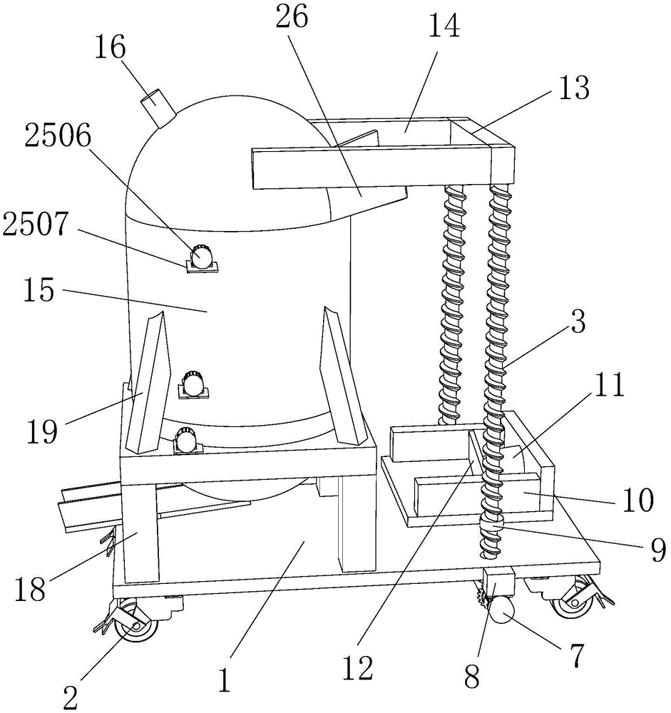
Cement mixing arrangement for building
Technical Field
The utility model relates to a construction technical field specifically is a cement mixing arrangement for building.
Background
The building industry is a production department specially engaged in civil engineering, building construction, equipment installation and engineering investigation and design work, the products are buildings, structures and facilities of various factories, mines, railways, bridges, ports, roads, pipelines, houses and public facilities, after the products of the building industry are transferred to users, various productive and non-productive fixed assets are formed, the products are means for production of various material production departments of national economy and transportation departments, the products are important material bases for people's life, cement is a powdery hydraulic inorganic cementing material, and is stirred into slurry by adding water, can be hardened in the air or better hardened in water, and can firmly bond materials such as sand, stone and the like together, and the cement is taken as an important cementing material for a long time and is widely applied to the projects such as civil engineering, water conservancy, national defense and the like, traditional cement mixing arrangement utilizes the axis of rotation to drive the puddler and mixes, and the condition of caking can appear in the place that can not stir, mixes inhomogeneously, leads to mixing effect not good, and traditional mixing arrangement needs to stir for a long time simultaneously, has reduced workman's work efficiency, and excessive extravagant manpower and materials can't satisfy user's result of use, and mixing time is long moreover, and the operation is complicated, is unfavorable for using and promoting.
SUMMERY OF THE UTILITY MODEL
Technical problem to be solved
Not enough to prior art, the utility model provides a cement mixing arrangement for building has solved and has mixed inhomogeneous, extravagant manpower and materials and the problem that work efficiency is low.
(II) technical scheme
In order to achieve the above purpose, the utility model discloses a following technical scheme realizes: a cement mixing device for buildings comprises a base, universal wheels are fixedly connected to four corners of the lower surface of the base, the front right surface of the base is fixedly connected with the rear end of a fixed block, the bottom end of the fixed block is fixedly connected with the top end of a first driving motor, the output end of the first driving motor is fixedly connected with the front surface of a second bevel gear, two groups of the second bevel gears are fixedly connected through a connecting shaft, the second bevel gear is meshed with a first bevel gear, the top end of the first bevel gear is fixedly connected with the bottom end of a threaded rod, the two groups of the threaded rod are respectively connected with the front end and the rear end of the right side of the base in a rotating manner, the threaded rod is connected with a nut bolt, two groups of nuts are respectively fixedly connected with the lower parts of the front side and the rear side of a cement hopper, the inner wall of the right side of the cement hopper is, the top ends of the two groups of threaded rods are respectively rotatably connected with the front end and the rear end of the limiting rod, the front end and the rear end of the left side of the limiting rod are respectively and fixedly connected with two groups of first fixing rods, the left end of each first fixing rod is fixedly connected with the top end of a cement barrel, the upper end of the left side of the cement barrel is provided with a water inlet, the upper end of the right side of the cement barrel is provided with a feed inlet, the bottom end of the cement barrel is fixedly connected with a support frame, the bottom end of the support frame is fixedly connected with the left side of the upper surface of the base, the bottom end of the cement barrel is provided with a discharge outlet, the discharge outlet is provided with a sliding cover, the bottom end of the left side of the cement barrel is fixedly connected with the right end of a first electric telescopic rod, the left end of the first electric telescopic rod is fixedly connected, the middle part of cement bucket is provided with three agitating unit of group, agitating unit includes the motor frame, the rear end of motor frame and the preceding left side fixed connection street of cement bucket, the upper surface of motor frame and second driving motor's lower extreme fixed connection, the front side wall that the cement bucket was passed to second driving motor's output and the front end fixed connection of pivot, the outer three fourth bevel gears of group of fixedly connected with of pivot, fourth bevel gear and third bevel gear meshing are connected, the right-hand member of third bevel gear and the left end fixed connection of pole screw, the right-hand member of pole screw rotates with the right side wall of cement bucket to be connected, the below of pole screw is provided with the baffle.
Preferably, the nut is provided with an internal thread, the threaded rod is provided with an external thread, and the internal thread of the nut is matched with the external thread of the threaded rod.
Preferably, the top end and the bottom end of the cement bucket are both semicircular, and the middle part of the cement bucket is cylindrical.
Preferably, four corners of the upper surface of the support frame are fixedly connected with the bottom end of the fixing frame, and the top end of the fixing frame is fixedly connected with the side wall of the cement bucket.
Preferably, the stirring device is provided with three groups, the top baffle and the bottom baffle are inclined downwards to the right, and the middle baffle is inclined downwards to the left.
Preferably, the right side of the feeding hole and the left side of the discharging hole are fixedly connected with guide grooves.
(III) advantageous effects
The utility model provides a cement mixing arrangement for building possesses following beneficial effect:
1. this cement mixing arrangement for building drives the cement through the nut and fights and go up and down, cooperates electronic catch bar to promote the push pedal, has reached laborsaving effect, is provided with three agitating unit of group through the cement bucket, can effectually improve stirring efficiency, is provided with three group's pole screws through among the agitating unit, has solved the inhomogeneous condition of current cement stirring.
2. This cement mixing arrangement for building through being provided with the universal wheel bottom the base, great reduction artificial use, through at cement bucket outside fixedly connected with mount, can be effectively fixed with the cement bucket, sets up to the hemisphere through the bottom with the cement bucket, makes this cement mixing arrangement for building still have the effect of the biggest row's material.
Drawings
FIG. 1 is a schematic structural view of the present invention;
FIG. 2 is a schematic view of a rod propeller according to the present invention;
FIG. 3 is a schematic structural view of the cement hopper of the present invention;
fig. 4 is a schematic structural view of the bottom of the present invention;
fig. 5 is a schematic structural diagram of the stirring device of the present invention.
In the figure: 1. a base; 2. a universal wheel; 3. a threaded rod; 4. a first bevel gear; 5. a second bevel gear; 6. a connecting shaft; 7. a first drive motor; 8. a fixed block; 9. a nut; 10. a cement hopper; 11. an electric push rod; 12. pushing the plate; 13. a limiting rod; 14. a first fixing lever; 15. a cement bucket; 16. a water inlet; 17. a feed inlet; 18. a support frame; 19. a fixed mount; 20. a discharge port; 21. a sliding cover; 22. A first electric telescopic rod; 23. a second electric telescopic rod; 24. a connecting rod; 25. a stirring device; 2501. a baffle plate; 2502. a rod propeller; 2503. a third bevel gear; 2504. a fourth bevel gear; 2505. a rotating shaft; 2506. a second drive motor; 2507. a motor frame; 26. a guide groove.
Detailed Description
The technical solutions in the embodiments of the present invention will be described clearly and completely with reference to the accompanying drawings in the embodiments of the present invention, and it is obvious that the described embodiments are only some embodiments of the present invention, not all embodiments. Based on the embodiments in the present invention, all other embodiments obtained by a person skilled in the art without creative work belong to the protection scope of the present invention.
Referring to fig. 1-5, the present invention provides a technical solution: a cement mixing device for buildings comprises a base 1, universal wheels 2 are fixedly connected to four corners of the lower surface of the base 1, the universal wheels 2 are arranged at the bottom of the base 1, manual use is greatly reduced, the right front surface of the base 1 is fixedly connected with the rear end of a fixed block 8, the bottom end of the fixed block 8 is fixedly connected with the top end of a first driving motor 7, the output end of the first driving motor 7 is fixedly connected with the front surface of a second bevel gear 5, the two groups of second bevel gears 5 are fixedly connected through a connecting shaft 6, the second bevel gear 5 is meshed with a first bevel gear 4, the top end of the first bevel gear 4 is fixedly connected with the bottom end of a threaded rod 3, the two groups of threaded rods 3 are respectively connected with the front end and the rear end of the right side of the base 1 in a rotating mode, the threaded rods 3 are connected with nuts 9 in a bolt mode, the nuts 9, two groups of nuts 9 are respectively fixedly connected with the lower parts of the front side and the rear side of a cement bucket 10, the inner wall of the right side of the cement bucket 10 is fixedly connected with the right end of an electric push rod 11, the left end of the electric push rod 11 is fixedly connected with the right side of a push plate 12, the cement bucket 10 is driven to lift by the nuts 9, the push plate 12 is pushed by the electric push rod 11 in a matching way, the labor-saving effect is achieved, the top ends of two groups of threaded rods 3 are respectively rotatably connected with the front end and the rear end of a limiting rod 13, the front end and the rear end of the left side of the limiting rod 13 are respectively fixedly connected with two groups of first fixing rods 14, the left end of each first fixing rod 14 is fixedly connected with the top end of a cement bucket 15, the top end and the bottom end of the cement bucket 15 are both semicircular, the middle part of the cement bucket 15 is cylindrical, the bottom of the cement bucket, the upper end of the right side of the cement barrel 15 is provided with a feeding hole 17, the bottom end of the cement barrel 15 is fixedly connected with a supporting frame 18, four corners of the upper surface of the supporting frame 18 are fixedly connected with the bottom end of a fixing frame 19, the cement barrel 15 can be effectively fixed by fixedly connecting the fixing frame 19 to the outer side of the cement barrel 15, the top end of the fixing frame 19 is fixedly connected with the side wall of the cement barrel 15, the bottom end of the supporting frame 18 is fixedly connected to the left side of the upper surface of the base 1, the bottom end of the left side of the cement barrel 15 is provided with a discharging hole 20, the right side of the feeding hole 17 and the left side of the discharging hole 20 are both fixedly connected with a sliding chute 26, the discharging hole 20 is provided with a sliding cover 21, the bottom end of the left side of the cement barrel 15 is fixedly connected with the right end of a first electric telescopic, the right end of the connecting rod 24 is fixedly connected with the left upper end of the sliding cover 21, three groups of stirring devices 25 are arranged in the middle of the cement barrel 15, the stirring efficiency can be effectively improved by arranging the three groups of stirring devices 25 in the cement barrel 15, the stirring devices 25 comprise a motor frame 2507, the rear end of the motor frame 2507 is fixedly connected with the left side in front of the cement barrel 15, the upper surface of the motor frame 2507 is fixedly connected with the lower end of a second driving motor 2506, the output end of the second driving motor 2506 penetrates through the front side wall of the cement barrel 15 to be fixedly connected with the front end of a rotating shaft 2505, three groups of fourth bevel gears 2504 are fixedly connected with the outer side of the rotating shaft 2505, the fourth bevel gears 2504 are meshed with the third bevel gears 2503, the right end of the third bevel gears 2503 is fixedly connected with the left end of the rod propeller 2502, and the existing uneven cement stirring situation is solved by arranging the three groups, the right end of the rod propeller 2502 is rotatably connected with the right side wall of the cement bucket 15, baffles 2501 are arranged below the rod propeller 2502, three groups of stirring devices 25 are arranged, the top baffles 2501 and the bottom baffles are inclined downwards to the right, and the middle baffles 2501 are inclined downwards to the left.
When in use, a user moves the cement mixing device for the building to the front of cement through the universal wheel 2, the cement is loaded into the cement bucket 10, the switch of the first driving motor 7 is started, the first driving motor 7 drives the threaded rod 3 to rotate through the connecting shaft 6, the cement bucket 10 is enabled to ascend, the user starts the electric push rod 11 according to the actual use condition, the push plate 12 is driven by the electric push rod 11 to move, so that cement falls into the guide groove 26 and enters the cement bucket 15 through the feed inlet 17, water is injected from the water inlet 16, the second driving motor 2506 is started, the second driving motor 2506 drives the third bevel gear 2503, the fourth bevel gear 2504 and the rod propeller 2502 to rotate through the rotating shaft 2505, the cement flows into the bottom of the cement bucket 15 through the baffle 2501, the cement is discharged from the guide groove 26 through the discharge port 20, and the user turns off the construction cement mixing device according to the actual mixing condition.
In conclusion, this cement mixing arrangement for building, it goes up and down to drive cement bucket 10 through nut 9, the electronic catch bar 11 of cooperation promotes push pedal 12, laborsaving effect has been reached, be provided with three agitating unit 25 of group in through cement bucket 15, can effectually improve stirring efficiency, be provided with three groups pole screw 2502 in agitating unit 25, the inhomogeneous condition of current cement stirring has been solved, through be provided with universal wheel 2 in base 1 bottom, great reduction artificial use, through at 15 outside fixedly connected with mount 19 of cement bucket, can be fixed cement bucket 15 effectively, bottom through with cement bucket 15 sets up to the hemisphere, make this cement mixing arrangement for building still have the effect of the biggest row material.
It is noted that, herein, relational terms such as first and second, and the like may be used solely to distinguish one entity or action from another entity or action without necessarily requiring or implying any actual such relationship or order between such entities or actions. Also, the terms "comprises," "comprising," or any other variation thereof, are intended to cover a non-exclusive inclusion, such that a process, method, article, or apparatus that comprises a list of elements does not include only those elements but may include other elements not expressly listed or inherent to such process, method, article, or apparatus.
The electrical components presented in the document are all electrically connected with an external master controller and 220V mains, and the master controller can be a conventional known device controlled by a computer or the like.
Although embodiments of the present invention have been shown and described, it will be appreciated by those skilled in the art that changes, modifications, substitutions and alterations can be made in these embodiments without departing from the principles and spirit of the invention, the scope of which is defined in the appended claims and their equivalents.