Background
In a construction work, a steel bar is used, and the steel bar can be used after being subjected to processing such as straightening, cutting, thread rolling, bending and the like.
Among the prior art, when carrying out the thread rolling to the reinforcing bar, need be fixed with the reinforcing bar by the manual work, and drive through motor and reduction gear and shell the rib dish and rotate, will shell the rib dish by the manual work and promote forward, thereby roll the thread to the reinforcing bar, but it is when using, has some problems, and it can only cut the one end of reinforcing bar, and after the cutting finishes, need dismantle the reinforcing bar by the manual work, and change the direction back, roll the thread to the other end, increased intensity of labour, reduced work efficiency.
SUMMERY OF THE UTILITY MODEL
To above defect, the utility model provides a rotary type reinforcing bar cuts off double-end thread rolling all-in-one to the problem of solution.
In order to achieve the above purpose, the utility model adopts the following technical scheme:
a rotary type reinforcing steel bar cutting double-end thread rolling integrated machine comprises a workbench, wherein a feeding cutting mechanism is arranged on the workbench, a fixing mechanism is arranged on one side of the feeding cutting mechanism, a pushing mechanism is arranged on one side of the fixing mechanism, a reinforcing steel bar thread rolling mechanism is arranged on the workbench, a rotating mechanism is arranged on one side of the reinforcing steel bar thread rolling mechanism,
the steel bar thread rolling mechanism comprises a rotating table positioned above a workbench, a plurality of first universal balls are arranged on the lower surface of the rotating table, the lower ends of the first universal balls fall on the upper surface of the workbench, a fixed table is arranged on one side of the upper surface of the rotating table, a speed reducing motor is arranged on the upper surface of the fixed table, a coupler is arranged at the rotating end of the speed reducing motor, a rotating shaft is arranged on one side of the coupler, one end of the rotating shaft is fixedly connected with the coupler, a first rolling bearing is arranged at one end of the rotating shaft, which is far away from the coupler, a support column is arranged at the lower end of the first rolling bearing, the lower end of the support column is fixedly arranged on the rotating table, a square connecting column is arranged on the surface of one side of the rotating shaft, a moving rod is arranged on one side of the rotating shaft, the lower end of the support rod is fixedly arranged on the rotating table, an internal thread is arranged in the hollow sleeve, the hollow sleeve is sleeved outside the moving rod, the moving rod is connected with the hollow sleeve through a thread, a rotating disc is arranged at one end of the moving rod, an arc-shaped support frame is arranged below the rotating disc, a plurality of second universal balls are arranged on the surface of the inner side of the arc-shaped support frame, a plurality of support legs are arranged on the lower surface of the arc-shaped support frame, a rib stripping disc is arranged on one side of the rotating disc, a plurality of rib stripping,
the rotating mechanism comprises a third rolling bearing fixedly arranged on the upper surface of the workbench, the third rolling bearing is positioned on one side of the rotating platform, a rotating column is arranged above the workbench, the lower end of the rotating column is inserted into the third rolling bearing, a connecting rod is arranged on one side of the upper end of the rotating column, one end of the connecting rod is fixedly connected with the surface of one side of the rotating platform, a transmission gear is arranged on the rotating shaft and is positioned between the first rolling bearing and the coupler, a square notch is formed in the rotating platform and is positioned below the transmission gear, connecting shafts are arranged on two sides above the square notch, fixing rods are arranged at the lower ends of two sides of the connecting shafts, the lower ends of the fixing rods are fixedly arranged on the upper surface of the rotating platform, a U-shaped rack is arranged on the upper surface of the workbench and is meshed with, the first electromagnet corresponds to the metal block in position, and two first infrared ranging sensors are installed on one side of the upper surface of the workbench.
Further, the U-shaped rack includes an arc rack and two lifting racks, the lifting racks are located square notch, surface mounting has a plurality of expanding springs under the lifting racks, surface fixed connection is gone up with the workstation to the expanding spring lower extreme, lifting racks lower extreme opens has a plurality of guiding holes, surface mounting has a plurality of guide posts on the workstation, the guiding post upper end inserts in the guiding hole, the metal sheet is installed to lifting racks both sides upper end, a plurality of second electro-magnets are installed to square notch both sides, arc rack fixed mounting is on the workstation, arc rack both ends and the laminating of lifting racks one end, the centre of a circle position of arc rack and the coincidence of the centre of a circle position of third antifriction bearing, first infrared ranging sensor is located lifting racks one side.
Further, feeding shutdown mechanism includes a plurality of drive wheels of fixed mounting at the workstation upper surface, the reinforcing bar is placed on the drive wheel, drive wheel one side is equipped with first rotating electrical machines, first rotating electrical machines fixed mounting is on the workstation, the rotatory end of first rotating electrical machines is connected with drive wheel one side fixed surface, the transmission shaft is installed to drive wheel opposite side surface, fourth antifriction bearing is installed to transmission shaft one end, the fixed column is installed to fourth antifriction bearing lower extreme, fixed column lower extreme fixed mounting is on the workstation, the reinforcing bar cutter is installed to workstation upper surface one side, second infrared ranging sensor is installed to workstation upper surface one side.
Furthermore, a driving wheel and a steel bar cutting machine are not arranged in the rotating range of the rotating table.
Further, the fixing mechanism comprises an L-shaped supporting plate positioned above the third rolling bearing, the lower end of the L-shaped supporting plate is fixedly arranged on the workbench, a rotating wheel is arranged above the L-shaped supporting plate, the upper end of the rotating wheel is level with the upper end of the driving wheel, a second rotating motor is arranged on the upper surface of the L-shaped supporting plate, the rotating end of the second rotating motor is fixedly connected with one side surface of the rotating wheel, a rotating rod is arranged on the other side surface of the rotating wheel, a fifth rolling bearing is arranged at one end of the rotating rod, a supporting strip is arranged at the lower end of the fifth rolling bearing, the lower end of the supporting strip is fixedly arranged on the upper surface of the L-shaped supporting plate, lifting tables are arranged on the two sides of the rotating wheel, an arc-shaped groove is formed in the upper ends of the lifting tables, lifting plates are arranged at the two side surfaces of the lifting, the elevating platform below is equipped with the promotion platform, promotes platform both sides surface both ends and installs the movable plate, and it has circular through hole to open on the movable plate, and circular through hole corresponds with circular through hole is concentric, and circular baffle is installed to the guide bar lower extreme, and circular baffle is located circular through hole below, promotes bench surface and elevating platform lower surface and passes through coupling spring to be connected, and the elevating platform both sides are equipped with the arc and compress tightly the platform, and arc recess and arc compress tightly a inboard and are equipped with anti-skidding line.
Furthermore, circular holes are formed in two sides of the arc-shaped pressing table, connecting screw rods are arranged on two sides of the arc-shaped pressing table, the lower ends of the connecting screw rods are fixedly mounted on the L-shaped supporting plate, two adjusting nuts are mounted on the connecting screw rods, and the adjusting nuts are located at the upper end and the lower end of the arc-shaped pressing table.
Further, the pushing mechanism comprises guide bars fixedly arranged on the inner sides of the lower ends of the guide bars, a moving block is arranged between the two guide bars, guide grooves are formed in two sides of the moving block, one end of each guide bar extends into each guide groove, pulleys are arranged on the lower surface of the moving block, the lower ends of the pulleys are placed on an L-shaped supporting plate, the lower surface of the pushing table is an inclined plane, a plurality of supporting wheels are arranged on the inclined plane, a first resetting table is arranged on one side of the moving block and connected with the moving block through a first resetting spring, a trapezoidal table is arranged on one side of the moving block, a first sliding block is arranged on the lower surface of the trapezoidal table, a first sliding way is arranged on the upper surface of the L-shaped supporting plate, the lower end of the first sliding block extends into the first sliding way, a pushing wheel is arranged on one side of the trapezoidal table, a second resetting table is arranged on one, second slide top is equipped with and promotes the piece, promotes a lower surface mounting and has the second slider, and in the second slide was stretched to the second slider lower extreme, promoted a side surface mounting and has the universal ball of third, and universal ball one end of third is located and shells rib dish one side, promotes a side and installs the board that resets, shells rib dish one side and installs the fixed plate, the fixed plate with reset the board and pass through the connection of third reset spring.
Further, the second slideway and the first slideway are at the same height.
The utility model has the advantages that: the device places the reinforcing steel bar on the front side of a rib stripping disc, drives the rib stripping disc to rotate through a speed reduction motor, and is connected with the hollow sleeve through a screw thread of a moving rod, the rib stripping disc can be pushed forwards to roll one end of the reinforcing steel bar, the reinforcing steel bar can be automatically fixed when the rib stripping disc moves to prevent the reinforcing steel bar from shaking, after the thread rolling on one end of the reinforcing steel bar is finished, the motor is started to rotate to enable the rib stripping disc to return to the original position, an electromagnet is closed to enable a lifting rack to rise and be meshed with a transmission gear, a rotating platform can rotate around a third rolling bearing through the rotation of the motor and avoid the front of the reinforcing steel bar, the reinforcing steel bar is continuously driven to move forwards, after the reinforcing steel bar moves for a certain distance, the reinforcing steel bar is cut through a reinforcing steel bar cutting machine, at the moment, the cut reinforcing steel bar moves forwards, the rest reinforcing steel bar does not move, the rib peeling disc moves to the other end of the steel bar, the steel bar is rolled, the device can cut the long steel bar into a short steel bar, and the two ends of the steel bar can be rolled, so that the device is convenient to use, reduces labor intensity and improves working efficiency.
Detailed Description
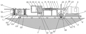
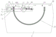
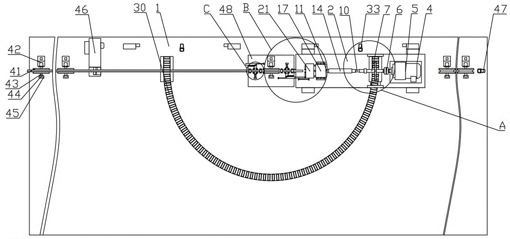
The invention is described in detail below with reference to the drawings, as shown in fig. 1-16: a rotary type reinforcing steel bar cutting double-end thread rolling integrated machine comprises a rotary type reinforcing steel bar cutting double-end thread rolling integrated machine, and comprises a workbench 1, wherein a feeding cutting mechanism is arranged on the workbench 1, a fixing mechanism is arranged on one side of the feeding cutting mechanism, a pushing mechanism is arranged on one side of the fixing mechanism, a reinforcing steel bar thread rolling mechanism is arranged on the workbench 1, a rotating mechanism is arranged on one side of the reinforcing steel bar thread rolling mechanism,
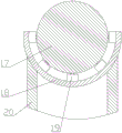
the steel bar thread rolling mechanism comprises a rotating table 2 positioned above a workbench 1, a plurality of first universal balls 3 are arranged on the lower surface of the rotating table 2, the lower ends of the first universal balls 3 fall on the upper surface of the workbench 1, a fixed table 4 is arranged on one side of the upper surface of the rotating table 2, a speed reducing motor 5 is arranged on the upper surface of the fixed table 4, a coupler 6 is arranged at the rotating end of the speed reducing motor 5, a rotating shaft 7 is arranged on one side of the coupler 6, one end of the rotating shaft 7 is fixedly connected with the coupler 6, a first rolling bearing 8 is arranged at one end, far away from the coupler 6, on the rotating shaft 7, a support column 9 is arranged at the lower end of the first rolling bearing 8, the lower end of the support column 9 is fixedly arranged on the rotating table 2, a square connecting column 10 is arranged on one side of the rotating shaft 7, a moving, the outer side of the moving rod 11 is provided with an external thread 13, a hollow sleeve 14 is arranged above the rotating platform 2, support rods 15 are arranged on two sides of the lower end of the hollow sleeve 14, the lower end of each support rod 15 is fixedly arranged on the rotating platform 2, an internal thread 16 is arranged in the hollow sleeve 14, the hollow sleeve 14 is sleeved on the outer side of the moving rod 11, the moving rod 11 is connected with the hollow sleeve 14 through a thread, a rotating disc 17 is arranged at one end of the moving rod 11, an arc-shaped support frame 18 is arranged below the rotating disc 17, a plurality of second universal balls 19 are arranged on the inner side surface of the arc-shaped support frame 18, a plurality of support legs 20 are arranged on the lower surface of the arc-shaped support frame 18, a,
the rotating mechanism comprises a third rolling bearing 23 fixedly arranged on the upper surface of the workbench 1, the third rolling bearing 23 is positioned on one side of the rotating platform 2, a rotating column 24 is arranged above the workbench 1, the lower end of the rotating column 24 is inserted into the third rolling bearing 23, a connecting rod 25 is arranged on one side of the upper end of the rotating column 24, one end of the connecting rod 25 is fixedly connected with the surface of one side of the rotating platform 2, a transmission gear 26 is arranged on the rotating shaft 7, the transmission gear 26 is positioned between the first rolling bearing 8 and the coupler 6, a square notch 27 is arranged on the rotating platform 2, the square notch 27 is positioned below the transmission gear 26, connecting shafts 28 are arranged on two sides above the square notch 27, fixing rods 29 are arranged at the lower ends of two sides of the connecting shafts 28, the lower ends of the fixing rods 29 are fixedly arranged on the upper surface of the rotating platform 2, a U-shaped rack 30 is arranged, four first electromagnets 32 are installed to 1 upper surface one side of workstation, first electromagnet 32 corresponds with the position of metal block 31, 1 upper surface one side of workstation installs two first infrared ranging sensor 33, rotation through gear motor 5, can drive carriage release lever 11 and shell the rotation of rib dish 21, threaded connection through carriage release lever 11 and hollow sleeve 14, can make shell the rib dish 21 to remove to the place ahead, thereby can roll the silk to the reinforcing bar, through the meshing of drive gear 26 and U-shaped rack 30, can drive and rotate platform 2 around the opposite side that third antifriction bearing 23 rotated the reinforcing bar, thereby conveniently roll the silk to the reinforcing bar both ends.
Further, the U-shaped rack 30 includes an arc-shaped rack 34 and two lifting racks 35, the lifting racks 35 are located at the square gap 27, a plurality of extension springs 36 are installed on the lower surface of the lifting racks 35, the lower ends of the extension springs 36 are fixedly connected with the upper surface of the workbench 1, a plurality of guide holes 37 are opened on the lower ends of the lifting racks 35, a plurality of guide posts 38 are installed on the upper surface of the workbench 1, the upper ends of the guide posts 38 are inserted into the guide holes 37, metal plates 39 are installed on the upper ends of both sides of the lifting racks 35, a plurality of second electromagnets 40 are installed on both sides of the square gap 27, the arc-shaped rack 34 is fixedly installed on the workbench 1, both ends of the arc-shaped rack 34 are attached to one end of the lifting racks 35, the position of the center of the arc-shaped rack 34 coincides with the position of the center of the third rolling bearing 23, the first infrared ranging sensor 33, the lifter rack 35 can be moved downward and sprung upward, so that the engagement and disengagement of the lifter rack 35 with the pinion 26 can be facilitated, and the turntable 2 can be rotated.
Further, the feeding cutting mechanism comprises a plurality of transmission wheels 41 fixedly arranged on the upper surface of the workbench 4, the steel bar is placed on the transmission wheels 41, a first rotating motor 42 is arranged on one side of the transmission wheels 41, the first rotating motor 42 is fixedly arranged on the workbench 1, the rotating end of the first rotating motor 42 is fixedly connected with the surface of one side of the transmission wheels 41, a transmission shaft 43 is arranged on the surface of the other side of the transmission wheels 41, a fourth rolling bearing 44 is arranged at one end of the transmission shaft 43, a fixed column 45 is arranged at the lower end of the fourth rolling bearing 44, the lower end of the fixed column 45 is fixedly arranged on the workbench 1, a steel bar cutting machine 46 is arranged on one side of the upper surface of the workbench 1, a second infrared ranging sensor 47 is arranged on one side of the upper surface of the workbench 1, the transmission wheels 41 can be driven to rotate by the first rotating, thereby facilitating cutting of the reinforcing bars using the bar cutter 46.
Furthermore, the transmission wheel 41 and the steel bar cutting machine 46 are not arranged in the rotating range of the rotating table 2, so that the rotating table 2 cannot collide with the transmission wheel 41 when rotating.
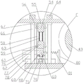
Further, the fixing mechanism comprises an L-shaped supporting plate 48 positioned above the third rolling bearing 23, the lower end of the L-shaped supporting plate 48 is fixedly installed on the workbench 1, a rotating wheel 49 is arranged above the L-shaped supporting plate 48, the upper end of the rotating wheel 49 is level with the upper end of the driving wheel 41, a second rotating motor 50 is installed on the upper surface of the L-shaped supporting plate 48, the rotating end of the second rotating motor 50 is fixedly connected with the surface of one side of the rotating wheel 49, a rotating rod 51 is installed on the surface of the other side of the rotating wheel 49, a fifth rolling bearing 52 is installed at one end of the rotating rod 51, a supporting bar 53 is installed at the lower end of the fifth rolling bearing 52, the lower end of the supporting bar 53 is fixedly installed on the upper surface of the L-shaped supporting plate 48, lifting platforms 54 are arranged on two sides of the rotating wheel 49, arc-shaped grooves 55 are formed in the upper ends of, the lower end of the guide rod 58 is fixedly installed on the L-shaped supporting plate 48, the upper end of the guide rod 58 penetrates through the circular through hole 57 and extends to one side of the lifting platform 54, a pushing platform 59 is arranged below the lifting platform 54, moving plates 60 are installed at two ends of the surfaces of two sides of the pushing platform 59, circular through holes 61 are formed in the moving plates 60, the circular through holes 61 correspond to the circular through holes 57 in a concentric mode, circular baffles 62 are installed at the lower end of the guide rod 58 and located below the circular through holes 61, the upper surface of the pushing platform 59 is connected with the lower surface of the lifting platform 54 through connecting springs 63, arc pressing platforms 64 are arranged on two sides of the lifting platform 54, anti-skid grains are arranged on the inner sides of the arc grooves 55 and the arc pressing platforms 64, the lifting platform 54 can be moved upwards through the passing of the.
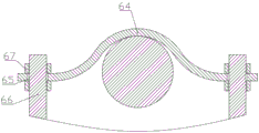
Furthermore, circular holes 65 are formed in two sides of the arc-shaped pressing table 64, connecting screw rods 66 are arranged on two sides of the arc-shaped pressing table 64, the lower ends of the connecting screw rods 66 are fixedly mounted on the L-shaped supporting plate 48, two adjusting nuts 67 are mounted on the connecting screw rods 66, the adjusting nuts 67 are located at the upper end and the lower end of the arc-shaped pressing table 64, and the positions of the arc-shaped pressing table 64 can be adjusted through rotation of the adjusting nuts 67, so that steel bars with different diameters can be rolled conveniently.
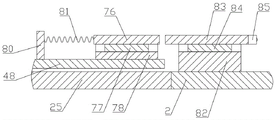
Further, the pushing mechanism comprises a guide bar 68 fixedly installed on the inner side of the lower end of the guide bar 58, a moving block 69 is arranged between the two guide bars 58, guide grooves 70 are formed in two sides of the moving block 69, one end of the guide bar 68 extends into the guide grooves 70, a pulley 71 is installed on the lower surface of the moving block 69, the lower end of the pulley 71 is placed on the L-shaped support plate 48, the lower surface of the pushing table 59 is an inclined surface 72, a plurality of support wheels 73 are installed on the inclined surface 72, a first resetting table 74 is installed on one side of the moving block 69, the first resetting table 74 and the moving block 69 are connected through a first resetting spring 75, a trapezoidal table 76 is installed on one side of the moving block 69, a first sliding block 77 is installed on the lower surface of the trapezoidal table 76, a first slide way 78 is installed on the upper surface of the L-shaped support plate 48, the lower end of the first sliding block 77 extends, the second reset table 80 is connected with the trapezoidal table 76 through a second reset spring 81, a second slide 82 is installed on one side of the upper surface of the rotating table 2, a pushing block 83 is arranged above the second slide 82, a second slide 84 is installed on the lower surface of the pushing block 83, the lower end of the second slide 84 extends into the second slide 82, a third universal ball 85 is installed on one side of the pushing block 83, one end of the third universal ball 85 is located on one side of the rib peeling disc 21, a reset plate 86 is installed on one side of the pushing block 83, a fixing plate 87 is installed on one side of the rib peeling disc 21, the fixing plate 87 and the reset plate 86 are connected through a third reset spring 88, when the rib peeling disc 21 moves forward, the pushing block 83 can be pushed to one side, the trapezoidal table 76, the moving block 69 and the pushing table 59 can move, so that the lifting table 54 can be conveniently lifted.
Furthermore, the second slide way 82 and the first slide way 78 are at the same height, so that when the pushing block 83 moves, the second slide block 84 falls into the first slide way 78, and the moving direction of the second slide block 84 is ensured.
In this embodiment, the electric equipment of the device is controlled by an external controller, a worker selects a suitable rib stripping thread rolling head 22 according to the diameter of the steel bar and installs the rib stripping thread rolling head on the rib stripping disc 21, two adjusting nuts 67 on a connecting screw 66 are rotated to adjust the height of the arc-shaped pressing table 64, the worker places a longer steel bar on the driving wheel 41, under a normal state, the advancing direction of the rib stripping disc 21 and the advancing square of the steel bar are in a vertical state, at this time, the driving gear 26 is meshed with the arc-shaped rack 34,
the first rotating motor 42 is started to rotate, the first rotating motor 42 drives the transmission wheel 41 to rotate, so that the steel bar can advance towards the direction of the steel bar cutting machine 46, the second infrared ranging sensor 47 detects the moving position of the steel bar, when one end of the steel bar moves to the position where the steel bar can be rolled, one end of the steel bar moves to one side above the rotating wheel 49 at the moment, one end of the steel bar needing to be rolled is positioned above the lifting platform 54 far away from one side of the steel bar cutting machine 46, the first rotating motor 42 is closed, so that the steel bar stops advancing, the speed reducing motor 5 is started to rotate, the speed reducing motor 5 drives the rotating shaft 7 and the transmission gear 26 to rotate reversely through the coupler 6, the transmission gear 26 is meshed with the lifting rack 35, the speed reducing motor 5 is installed on the rotating platform 2 through the fixed platform 4, one end of the rotating platform 2 is connected, the rotating table 2 can rotate around the third rolling bearing 23, the square notch 27 formed on the rotating table 2 can facilitate the rotating table 2 to pass through the arc-shaped rack 34 and the lifting rack 35, the connecting shaft 28 and the fixing rod 29 can connect the two rotating tables 2 to synchronously rotate, so that the rotating table 2 can rotate to the position where the advancing direction of the rib stripping disc 21 is consistent with the advancing direction of the reinforcing steel bar, the rotating table 2 is positioned at the position far away from the reinforcing steel bar cutting machine 46 at the moment, the first universal ball 3 can reduce the friction force when the rotating table 2 moves, the transmission gear 26 is firstly meshed with the arc-shaped rack 34 and then meshed with the lifting rack 35, the rotating table 2 can rotate to the right position, the position of the rotating table 2 is detected through the first infrared distance measuring sensor 33, when the metal block 31 on the surface of one side of the rotating table 2 is jointed with the first electromagnet 32, the speed reducing motor 5 is closed, and the first electromagnet 32 is powered on at the, the metal block 31 is attracted, and the rotating table 2 is fixed,
when the gear motor 5 drives the rotating shaft 7 to rotate reversely, the square connecting column 10 at one end of the rotating shaft 7 is driven to rotate, one end of the square connecting column 10 is positioned in the square groove 12 in the moving rod 11, so that the moving rod 11 can be driven to rotate, the moving rod 11 is connected with the internal thread 16 in the hollow sleeve 14 through the external thread 13, so that when the moving rod 11 rotates reversely, the moving rod 11, the rotating disc 17 and the rib stripping disc 21 can move towards the direction close to the gear motor 5 while rotating, after the rotating table 2 is fixed, the gear motor 5 stops rotating, at the moment, the moving rod 11, the rotating disc 17 and the rib stripping disc 21 are static, the second electromagnet 40 is started, the metal plate 39 is attracted by the electromagnet 40 and pulled downwards, so that the lifting rack 26 moves downwards, thereby the connection between the transmission gear 26 and the lifting rack 35 is disconnected, the telescopic spring 36 is compressed, the guide column 38 and the guide hole 37 can ensure the moving direction of the lifting rack 35, when the transmission gear 26 is meshed with the lifting rack 35 to rotate, the lifting rack 35 can be prevented from shaking, the gear motor 5 is started to rotate forwards, the rotating shaft 7, the moving rod 11, the rotating disc 17 and the rib stripping disc 21 are driven to rotate forwards, the moving rod 11, the rotating disc 17 and the rib stripping disc 21 move towards the direction close to the reinforcing steel bar, the reinforcing steel bar is rolled by the rib stripping thread rolling head 22, when the rotating disc 17 rotates, the rotating disc 17 can be supported by the arc-shaped support frame 18, the second universal ball 19 and the support leg 20, the friction force generated when the rotating disc 17 moves can be reduced by the second universal ball 19, after thread rolling is finished, the gear motor 5 is started to rotate backwards, the moving rod 11, the rotating disc 17 and the rib stripping disc 21 are brought back to the original position,
when the rib peeling disc 21 moves towards the direction close to the reinforcing steel bar, the pushing block 83 can move towards the direction close to the reinforcing steel bar, the third universal ball 85 can reduce the friction force between the rib peeling disc 21 and the pushing block 83 when the rib peeling disc 21 rotates, the second slide block 84 and the second slide way 82 can ensure the moving direction of the pushing block 83, when the pushing block 83 moves, the third return spring 88 can be stretched and the trapezoidal platform 76 can be pushed towards one side, the first slide block 77 and the first slide way 78 below the trapezoidal platform 76 can ensure the moving direction of the trapezoidal platform 76, when the trapezoidal platform 76 moves, the second return spring 81 can be compressed and the moving block 69 can be pushed towards one side, the pushing wheel 79 can reduce the friction force between the trapezoidal platform 76 and the moving block 69, when the moving block 69 moves, the moving direction of the moving block 69 can be ensured through the guide strip 68 and the guide groove 70, the first return spring 75 is compressed, when the moving block 69 moves, the pushing table 59 can be pushed upwards, the moving block 60, the circular through hole 61 and the guide rod 58 on both sides of the pushing table 59 can ensure the moving direction of the pushing table 59, when the pushing table 59 moves upwards, the connecting spring 63 can be pushed upwards, so that the lifting table 54 is pushed upwards, the lifting plate 56, the circular through hole 57 and the guide rod 58 can ensure the moving direction of the lifting table 54, when the lifting table 54 moves upwards, the arc-shaped groove 55 can be pushed to the lower part of the reinforcing steel bar and the reinforcing steel bar is pushed upwards, the arc-shaped pressing tables 64 on both sides of the lifting table 54 block the reinforcing steel bar to prevent the reinforcing steel bar from moving, so that the reinforcing steel bar is fixed, the anti-skid thread can prevent the reinforcing steel bar from rotating, at the moment, the rib stripping thread rolling head 22 starts to contact with the reinforcing steel bar, and the larger the displacement of the pushing table 59 upwards along with the deep thread rolling, the stronger the compression in the, the reinforcing steel bars can be prevented from moving, when the thread rolling is finished and the rib stripping disc 21 retracts, the pushing block 83, the trapezoidal table 76 and the moving block 69 can be pulled back to the original positions under the elastic force action of the third return spring 88, the second return spring 81 and the first return spring 75, the pushing table 59 and the lifting table 54 move downwards under the action of gravity, the moving plates 60 at the two sides of the pushing table 59 are blocked by the circular baffle plate 62, the pushing table 59 can be prevented from continuously falling, and therefore the fixing of the reinforcing steel bars is loosened,
after the thread rolling of one end of the steel bar is finished, the first electromagnet 32 and the second electromagnet 40 are closed, the metal block 31 is disconnected with the first electromagnet 32, the metal plate 39 is disconnected with the second electromagnet 40, the lifting rack 35 pushes the lifting rack 35 upwards under the action of the elastic force of the extension spring 36, the lifting rack 35 is meshed with the transmission gear 26, the speed reduction motor 5 is started to rotate reversely, the rotating shaft 7 and the transmission gear 26 are driven to rotate, the rotating table 2 can be moved to a normal position through the meshing of the transmission gear 26, the lifting rack 35 and the arc-shaped rack 34, the first rotating motor 42 is started to rotate, the transmission wheel 41 is driven to rotate, the steel bar can continue to advance, the second infrared distance measuring sensor 47 detects the distance between one end of the steel bar and the second infrared distance measuring sensor 47, and when the steel bar reaches the length required to be cut, the first rotating motor 42 is closed, and the steel bar is cut off by starting the steel bar cutting machine 46, at this time, only the first rotating motor 42 and the second rotating motor 50 at the rear side of the steel bar cutting machine 46 are started, the cut steel bar is moved to the rear side, the first rotating motor 42 at the front side of the steel bar cutting machine 46 is closed, the position of the steel bar is detected by the second infrared ranging sensor 47, when the cut steel bar is moved to the position capable of rolling the other end of the steel bar, the first rotating motor 42 and the second rotating motor 50 are closed, the reducing motor 5 is started to rotate forward, the rotating table 2 is rotated to the position close to the steel bar cutting machine 46, at this time, the first electromagnet 32 and the second electromagnet 40 at the corresponding positions are started, the metal block 31 and the metal plate 39 are respectively attracted, the reducing motor 5 is continuously started to rotate forward, the moving rod 11, the rotating disc 17 and the rib peeling disc 21 are moved to the direction close to the steel bar, and the steel bar is, carry out the thread rolling to the reinforcing bar, finish the back with the reinforcing bar other end thread rolling, start gear motor 5 reversal, make after rib peeling thread rolling head 22 breaks away from the reinforcing bar, close first electro-magnet 32 and second electro-magnet 40, start gear motor 5 reversal, will rotate platform 2 and rotate the position under the normality, the reinforcing bar that the two thread rolling was finished is taken off and is collected by the staff, repeat the above-mentioned process, can separate into a plurality of shorter reinforcing bars with a longer reinforcing bar, and thread rolling to the reinforcing bar both ends, the last surplus defective material of longer reinforcing bar, take off by the staff and collect, and change the next longer reinforcing bar, thread rolling after cutting off it.
Above-mentioned technical scheme has only embodied the utility model discloses technical scheme's preferred technical scheme, some changes that this technical field's technical personnel probably made to some parts wherein have all embodied the utility model discloses a principle belongs to within the protection scope of the utility model.