CN212284892U - Gravity grain separator - Google Patents
Gravity grain separator Download PDFInfo
- Publication number
- CN212284892U CN212284892U CN202020884552.4U CN202020884552U CN212284892U CN 212284892 U CN212284892 U CN 212284892U CN 202020884552 U CN202020884552 U CN 202020884552U CN 212284892 U CN212284892 U CN 212284892U
- Authority
- CN
- China
- Prior art keywords
- box
- wall
- gravity
- millet
- box body
- Prior art date
- Legal status (The legal status is an assumption and is not a legal conclusion. Google has not performed a legal analysis and makes no representation as to the accuracy of the status listed.)
- Expired - Fee Related
Links
- 230000005484 gravity Effects 0.000 title claims abstract description 19
- 244000062793 Sorghum vulgare Species 0.000 claims abstract description 19
- 235000019713 millet Nutrition 0.000 claims abstract description 19
- 230000017525 heat dissipation Effects 0.000 claims abstract description 15
- 238000004140 cleaning Methods 0.000 claims description 20
- 235000013339 cereals Nutrition 0.000 claims description 16
- 239000010865 sewage Substances 0.000 claims description 10
- 239000002699 waste material Substances 0.000 claims description 10
- 230000005540 biological transmission Effects 0.000 claims description 9
- 239000000463 material Substances 0.000 claims description 4
- 239000000428 dust Substances 0.000 abstract description 13
- 239000012535 impurity Substances 0.000 abstract description 12
- 238000012216 screening Methods 0.000 abstract description 7
- 238000000034 method Methods 0.000 abstract description 6
- 238000000926 separation method Methods 0.000 abstract description 2
- 241000209094 Oryza Species 0.000 description 9
- 235000007164 Oryza sativa Nutrition 0.000 description 9
- 235000009566 rice Nutrition 0.000 description 9
- 206010024796 Logorrhoea Diseases 0.000 description 6
- 230000000694 effects Effects 0.000 description 6
- 238000005192 partition Methods 0.000 description 5
- 235000021329 brown rice Nutrition 0.000 description 2
- 238000005299 abrasion Methods 0.000 description 1
- 230000009286 beneficial effect Effects 0.000 description 1
- 230000007547 defect Effects 0.000 description 1
- 239000011148 porous material Substances 0.000 description 1
- 230000003014 reinforcing effect Effects 0.000 description 1
- 238000007873 sieving Methods 0.000 description 1
- 238000009423 ventilation Methods 0.000 description 1
Images


Landscapes
- Combined Means For Separation Of Solids (AREA)
Abstract
The utility model discloses a rough separator of gravity millet belongs to the rough separation technical field of millet, and its lower fixed surface that includes the upper surface of box and motor is connected, the output shaft joint of motor has the carousel, the front of carousel and the one end fixed connection at the fixed axle back, the top joint of bearing and transfer line is passed through on the top of fixed axle. This rough separator of gravity millet, through setting up the air exhauster, filter screen and heat dissipation box, the sieve screens out a large amount of little impurity during the screening, and assemble the collection through the guide plate, the air current in the second honeycomb duct that the air exhauster passes through will clearing up the box is taken out afterwards, the great impurity of the rough remaining dust of millet and light that the clearing up box will be falling the in-process through first honeycomb duct inhales, make it adsorb at the filter screen surface under the guide of air current, this kind of mode can filter a large amount of dust and impurity, make its box inside be difficult for piling up the dust, reduced wearing and tearing in a certain extent and promoted the life-span that equipment used.
Description
Technical Field
The utility model belongs to the technical field of the husky separation of millet, specifically be a gravity husky separator of millet.
Background
The gravity grain separator is a device for separating grain from brown rice by increasing automatic classification by utilizing the difference of specific gravity, granularity and surface friction coefficient among the grain from brown rice and under the action of a working plate which inclines in two directions and reciprocates, however, the existing grain separator generates a large amount of dust in the screening process, and does not have a structure which is convenient to process, and the dust is accumulated in the machine to cause the abrasion of the device structure to be enhanced in long-time use.
SUMMERY OF THE UTILITY MODEL
Technical problem to be solved
In order to overcome the above-mentioned defect of prior art, the utility model provides a rough separator of gravity millet has solved current rough separator of millet and has produced a large amount of dusts and do not have the structure of facilitating the processing at the in-process of screening, and the dust is piled up the problem that causes the reinforcing of equipment structure wearing and tearing in the machine is inside in long-time the use.
(II) technical scheme
In order to achieve the above object, the utility model provides a following technical scheme: a gravity grain rough separator comprises a box body, wherein the upper surface of the box body is fixedly connected with the lower surface of a motor, the output shaft of the motor is connected with a rotary disc in a clamping manner, the front surface of the rotary disc is fixedly connected with one end of the back surface of a fixed shaft, the top end of the fixed shaft is connected with the top end of a transmission rod in a clamping manner through a bearing, the bottom end of the transmission rod is movably connected with the top end of a slide rod through a pin shaft, the bottom end of the slide rod is movably connected with the upper surface of a sieve plate through a pin shaft, the right side surface of the sieve plate is movably connected with the right side surface of the inner wall of the box body through a pin shaft, a conveying belt body is arranged in the box body, the left side surface of the inner wall of the box body is communicated with the bottom end of a first guide pipe, the top end of the first, the lower surface of box inner wall is provided with the drawer, the upper surface joint of box inner wall has the feeder hopper, the four corners department of box lower surface all sets up and the support, the upper surface of box inner wall and the upper surface fixed connection of mount, the front of mount is through the back swing joint of round pin axle with the sliding sleeve, the sliding sleeve cup joints the surface at the slide bar.
As a further aspect of the present invention: the right side of the box body is provided with a sewage draining hole, the lower surface of the inner wall of the sewage draining hole is fixedly connected with the lower surface of the guide plate, and the guide plate is arranged in the box body.
As a further aspect of the present invention: the surface of conveyer belt body is provided with a plurality of sieve mesh, this internal arc cover that is provided with of conveyer belt, the upper surface of arc cover is provided with the baffle.
As a further aspect of the present invention: the air outlet of air exhauster is linked together with the left surface of heat dissipation box inner wall, the right flank of heat dissipation box is provided with the shutter, the motor is located the heat dissipation box.
As a further aspect of the present invention: the cleaning device comprises a cleaning box, the lower surface of the inner wall of the cleaning box is communicated with the top end of the first flow guide pipe, the lower surface of the inner wall of the cleaning box is fixedly connected with the lower surface of the partition plate, a filter screen is arranged on the left side surface of the partition plate, the lower surface of the inner wall of the cleaning box is communicated with the bottom end of the second flow guide pipe, and a cover plate is arranged on the left side surface of the cleaning box.
As a further aspect of the present invention: the right flank of box and the left flank fixed connection of wastes material box, the lower surface of wastes material box is linked together with the top of blow off pipe, the blow off pipe all is provided with the striker plate with the right flank of play hopper.
(III) advantageous effects
Compared with the prior art, the beneficial effects of the utility model reside in that:
1. this rough separator of gravity millet, through setting up the air exhauster, the clearance box, the baffle, filter screen and heat dissipation box, the sieve sieves a large amount of little impurity when sieving, and assemble the collection through the guide plate, the air current in the second honeycomb duct that the air exhauster passes through will clearing up the box is taken out afterwards, the clearance box is inhaled through the great impurity of the coarse remaining dust of millet and light of first honeycomb duct in-process falling, make it adsorb at the filter screen surface under the guide of air current, this kind of mode can filter a large amount of dust and impurity, the air current that goes out the fan simultaneously gets into the heat dissipation box and cools down the processing to the motor, make its box inside be difficult for piling up the dust, reduced wearing and tearing in a certain extent and promoted the life-span of equipment use.
2. This rough separator of gravity millet, through setting up the motor, the carousel, the transfer line, slide bar and conveyer belt body, when using, motor and conveyer belt body begin to start, the motor drives the carousel rotation, the carousel passes through the transfer line and drives the slide bar activity from top to bottom, the slide bar drives the sieve and constantly shakes, the sieve is to the rough screening of millet in the vibrations, the rough millet after the screening subsequently drops on the conveyer belt body, the rough millet after the impurity screening moves right on the conveyer belt body, garrulous rice in the rough millet etc. drops through the sieve mesh and assembles in the drawer at last, the rough millet of handling the end is discharged through a hopper, can separately handle discarded object and garrulous rice and dust, make its aftertreatment of conveniently distinguishing.
3. This rough separator of gravity millet, through setting up the arc cover, the mount, the sliding sleeve, apron and heat dissipation box, through setting up the arc cover, when the sieve mesh of seting up at the conveyer belt body sieves the garrulous rice, the landing before to dropping under the effect of arc cover downwards, make its garrulous rice conveniently get into the drawer, through setting up the mount, it is spacing to the slide bar in mount and the sliding sleeve cooperation, make it keep directional activity, through setting up the heat dissipation box, play the guard action to the motor, and can prevent that inside heat from gathering in the cooperation of air exhauster is used, play fine radiating effect.
Drawings
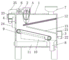
Fig. 1 is a schematic front view of a cross-sectional structure of the present invention;
fig. 2 is an enlarged schematic structural view at a position a of the present invention;
FIG. 3 is a schematic view of a front view of the cleaning device of the present invention;
in the figure: the device comprises a box body 1, a heat dissipation box 2, a waste box 3, a cleaning device 4, a cleaning box 41, a partition plate 42, a filter screen 43, a motor 5, a suction fan 6, a feed hopper 7, a discharge hopper 8, a conveyor belt body 9, an arc cover 10, a drawer 11, a sieve plate 12, a guide plate 13, a rotating disc 14, a fixed shaft 15, a transmission rod 16, a slide rod 17, a sliding sleeve 18, a fixed frame 19, a through hole 20, a sewage discharge hole 21, a sewage discharge pipe 22, a cover plate 23, a first flow guide pipe 24 and a second flow guide pipe 25.
Detailed Description
The technical solution of the present patent will be described in further detail with reference to the following embodiments.
As shown in fig. 1-3, the utility model provides a technical solution: a gravity grain rough separator comprises a box body 1, the upper surface of the box body 1 is fixedly connected with the lower surface of a motor 5, an output shaft of the motor 5 is connected with a rotary table 14 in a clamping manner, the front surface of the rotary table 14 is fixedly connected with one end of the back surface of a fixed shaft 15, the top end of the fixed shaft 15 is connected with the top end of a transmission rod 16 in a clamping manner through a bearing, the bottom end of the transmission rod 16 is movably connected with the top end of a slide rod 17 through a pin shaft, the bottom end of the slide rod 17 is movably connected with the upper surface of a sieve plate 12 through a pin shaft, the right side surface of the sieve plate 12 is movably connected with the right side surface of the inner wall of the box body 1 through a pin shaft, a conveying belt body 9 is arranged in the box body 1, the left side surface of the inner wall of the box body 1 is communicated with the bottom end of a first, can take the air current out in the clearance box 41, make it to form the negative pressure suction dirty in the clearance box 41, can play radiating effect to motor 5 simultaneously, the lower surface joint of 1 inner wall of box has out hopper 8, the lower surface of 1 inner wall of box is provided with drawer 11, the upper surface joint of 1 inner wall of box has feeder hopper 7, the four corners department of 1 lower surface of box all sets up and the support, the upper surface of 1 inner wall of box and the last fixed surface of mount 19 are connected, mount 19 openly through the back swing joint of round pin axle with sliding sleeve 18, sliding sleeve 18 cup joints the surface at slide bar 17.
Specifically, as shown in fig. 1, a sewage discharge hole 21 is formed on the right side surface of a box body 1, the lower surface of the inner wall of the sewage discharge hole 21 is fixedly connected with the lower surface of a guide plate 13, the guide plate 13 is arranged in the box body 1, a plurality of sieve pores are arranged on the surface of a conveyor belt body 9, an arc cover 10 is arranged in the conveyor belt body 9, a baffle is arranged on the upper surface of the arc cover 10, an air outlet of an exhaust fan 6 is communicated with the left side surface of the inner wall of a heat dissipation box 2, a louver is arranged on the right side surface of the heat dissipation box 2, a motor 5 is positioned in the heat dissipation box 2, the right side surface of the box body 1 is fixedly connected with the left side surface of a waste box 3, the lower surface of the waste box 3 is communicated with the top end of a sewage discharge pipe 22, baffle plates are arranged on the right side surfaces of the sewage discharge pipe 22 and a discharge hopper, convenient unified processing of carrying out, through setting up conveyer belt body 9, a plurality of sieve mesh has been seted up on conveyer belt body 9 surface, can come out the broken rice screening in husky millet, through setting up the shutter, can prevent that external world from dripping when convenient ventilation from getting into inside, through setting up waste material box 3, waste material box 3 can be built up a large amount of impurity in, discharge when needing can, through setting up blow off pipe 22, the right flank of blow off pipe 22 is provided with the striker plate, the striker plate can seal blow off pipe 22, prevent that inside filth from revealing.
Specifically, as shown in fig. 1, the cleaning device 4 includes a cleaning box 41, the lower surface of the inner wall of the cleaning box 41 is communicated with the top end of the first flow guide pipe 24, the lower surface of the inner wall of the cleaning box 41 is fixedly connected with the lower surface of the partition plate 42, the left side surface of the partition plate 42 is provided with a filter screen 43, the lower surface of the inner wall of the cleaning box 41 is communicated with the bottom end of the second flow guide pipe 25, the left side surface of the cleaning box 41 is provided with a cover plate 23, through the arrangement of the cleaning box 41, negative pressure can be formed on the inside under the action of the exhaust fan 6, dust and dirt are collected, the cleaning box is blocked in cooperation with the filter screen 43, and the unified treatment of workers.
The utility model discloses a theory of operation does:
s1, when the screen plate is used by a worker, firstly, the motor 5 and the conveyor belt body 9 are started, the motor 5 drives the turntable 14 to rotate, the turntable 14 drives the transmission rod 16 to move through the fixed shaft 15, and the transmission rod 16 drives the sliding rod 17 to reciprocate up and down and simultaneously drives the screen plate 12 to move up and down;
s2, starting the exhaust fan 6, leading in grain roughness through the feed hopper 7 by an operator, continuously vibrating the grain roughness under the action of the sieve plate 12 to screen out impurities in the grain roughness, gathering the impurities screened by the sieve plate 12 into the waste box 3 through the guide plate 13, and allowing light impurities, dust and the like to enter the cleaning box 41 under the suction action of the first guide pipe 24 when the grain roughness falls off on the sieve plate 12, and then accumulating the dust and the impurities under the action of the filter screen 43 in the continuous suction process of the exhaust fan 6;
s3, remaining rough rice drops on conveyer belt body 9, and garrulous rice wherein drops through the sieve mesh on conveyer belt body 9 surface and assembles in drawer 11 at last, and remaining rough rice is discharged through play hopper 8, and when using, the staff need regularly open blow off pipe 22 and apron 23 and clear up inside filth, and handles garrulous rice in the drawer 11.
In the description of the present invention, it is to be noted that, unless otherwise explicitly specified or limited, the terms "mounted," "connected," and "connected" are to be construed broadly, and may be, for example, fixedly connected, detachably connected, or integrally connected; can be mechanically or electrically connected; they may be connected directly or indirectly through intervening media, or they may be interconnected between two elements. The specific meaning of the above terms in the present invention can be understood by those of ordinary skill in the art through specific situations.
Although the preferred embodiments of the present patent have been described in detail, the present patent is not limited to the above embodiments, and various changes can be made without departing from the spirit of the present patent within the knowledge of those skilled in the art.
Claims (6)
1. The utility model provides a rough separator of gravity millet, includes box (1), its characterized in that: the upper surface of the box body (1) is fixedly connected with the lower surface of the motor (5), the output shaft of the motor (5) is connected with a rotary table (14), the front surface of the rotary table (14) is fixedly connected with one end of the back surface of a fixed shaft (15), the top end of the fixed shaft (15) is connected with the top end of a transmission rod (16) through a bearing, the bottom end of the transmission rod (16) is movably connected with the top end of a sliding rod (17) through a pin shaft, the bottom end of the sliding rod (17) is movably connected with the upper surface of a sieve plate (12) through a pin shaft, the right side surface of the sieve plate (12) is movably connected with the right side surface of the inner wall of the box body (1) through a pin shaft, a conveying belt body (9) is arranged in the box body (1), the left side surface of the inner wall of the box body (1) is communicated with the bottom end of a first guide pipe, the lower surface of cleaning device (4) is linked together through the air intake of second honeycomb duct (25) with air exhauster (6), the lower surface joint of box (1) inner wall has out hopper (8), the lower surface of box (1) inner wall is provided with drawer (11), the upper surface joint of box (1) inner wall has feeder hopper (7), the four corners department of box (1) lower surface all sets up and the support, the upper surface of box (1) inner wall and the last fixed surface of mount (19) are connected, the front of mount (19) is through the back swing joint of round pin axle with sliding sleeve (18), sliding sleeve (18) cup joint the surface at slide bar (17).
2. A gravity grain separator as claimed in claim 1 wherein: the box body is characterized in that a sewage discharge hole (21) is formed in the right side face of the box body (1), the lower surface of the inner wall of the sewage discharge hole (21) is fixedly connected with the lower surface of the guide plate (13), and the guide plate (13) is arranged in the box body (1).
3. A gravity grain separator as claimed in claim 1 wherein: the surface of conveyer belt body (9) is provided with a plurality of sieve mesh, be provided with arc cover (10) in conveyer belt body (9), the upper surface of arc cover (10) is provided with the baffle.
4. A gravity grain separator as claimed in claim 1 wherein: the air outlet of air exhauster (6) is linked together with the left flank of heat dissipation box (2) inner wall, the right flank of heat dissipation box (2) is provided with the shutter, motor (5) are located heat dissipation box (2).
5. A gravity grain separator as claimed in claim 1 wherein: cleaning device (4) are including clearance box (41), the lower surface of clearance box (41) inner wall is linked together with the top of first honeycomb duct (24), the lower surface of clearance box (41) inner wall and the lower fixed surface of baffle (42) are connected, the left surface of baffle (42) is provided with filter screen (43), the lower surface of clearance box (41) inner wall is linked together with the bottom of second honeycomb duct (25), the left surface of clearance box (41) is provided with apron (23).
6. A gravity grain separator as claimed in claim 1 wherein: the right flank of box (1) and the left flank fixed connection of wastes material box (3), the lower surface of wastes material box (3) is linked together with the top of blow off pipe (22), blow off pipe (22) all are provided with the striker plate with the right flank of play hopper (8).
Priority Applications (1)
| Application Number | Priority Date | Filing Date | Title |
|---|---|---|---|
| CN202020884552.4U CN212284892U (en) | 2020-05-25 | 2020-05-25 | Gravity grain separator |
Applications Claiming Priority (1)
| Application Number | Priority Date | Filing Date | Title |
|---|---|---|---|
| CN202020884552.4U CN212284892U (en) | 2020-05-25 | 2020-05-25 | Gravity grain separator |
Publications (1)
| Publication Number | Publication Date |
|---|---|
| CN212284892U true CN212284892U (en) | 2021-01-05 |
Family
ID=73969495
Family Applications (1)
| Application Number | Title | Priority Date | Filing Date |
|---|---|---|---|
| CN202020884552.4U Expired - Fee Related CN212284892U (en) | 2020-05-25 | 2020-05-25 | Gravity grain separator |
Country Status (1)
| Country | Link |
|---|---|
| CN (1) | CN212284892U (en) |
Cited By (1)
| Publication number | Priority date | Publication date | Assignee | Title |
|---|---|---|---|---|
| CN116326350A (en) * | 2023-05-30 | 2023-06-27 | 佳木斯市恒泰橡胶制品有限责任公司 | Harvester machine carries screening plant |
-
2020
- 2020-05-25 CN CN202020884552.4U patent/CN212284892U/en not_active Expired - Fee Related
Cited By (2)
| Publication number | Priority date | Publication date | Assignee | Title |
|---|---|---|---|---|
| CN116326350A (en) * | 2023-05-30 | 2023-06-27 | 佳木斯市恒泰橡胶制品有限责任公司 | Harvester machine carries screening plant |
| CN116326350B (en) * | 2023-05-30 | 2023-08-04 | 佳木斯市恒泰橡胶制品有限责任公司 | Harvester machine carries screening plant |
Similar Documents
| Publication | Publication Date | Title |
|---|---|---|
| CN219024570U (en) | Automatic crushing and processing device for construction waste | |
| CN113441213A (en) | Coal mining subsidence area gangue filling is with smashing conveying equipment | |
| CN215611872U (en) | A crushing device for sand in the manufacture of discarded tiles | |
| CN110449360B (en) | Environment-friendly dust removal winnowing machine | |
| CN210357955U (en) | Straw dust collecting equipment | |
| CN105286079A (en) | Method for separating and collecting tobacco fines generated after tobacco stems are threshed and redried | |
| CN211437025U (en) | Pulse type environment-friendly cleaning sieve | |
| CN221386617U (en) | Crushing device with dust removing mechanism | |
| CN221360469U (en) | Negative pressure grading clean separation system | |
| CN117443499B (en) | Barrel type metal separator | |
| CN207857337U (en) | Device for vibration screening | |
| CN217190932U (en) | Grain impurity removal conveyor | |
| CN214642859U (en) | Shot cleaning type shot blasting machine | |
| CN212916562U (en) | Novel clear powder screening device | |
| CN213255652U (en) | An air sieve type seed cleaner that is easy to clean up light impurities | |
| CN213001146U (en) | Dustless vibrating screen | |
| CN114308639A (en) | Particle type vibration separator convenient to reject | |
| CN211216951U (en) | A dust-proof sand screening and recycling machine | |
| CN210701092U (en) | Vibration screening device for crushing copper-aluminum water tank | |
| CN221536962U (en) | Magnetic separation impurity remover for seeds | |
| CN210023196U (en) | A dust-proof device for a soil sifter | |
| CN219150659U (en) | Improved feeding structure of miniature potato multistage sorting machine | |
| CN223405108U (en) | Agricultural medicament raw material screening and purifying equipment | |
| CN221108950U (en) | Powder feeding sieve bin | |
| CN215465274U (en) | Separation device for pepper seeds and pepper sections |
Legal Events
| Date | Code | Title | Description |
|---|---|---|---|
| GR01 | Patent grant | ||
| GR01 | Patent grant | ||
| CF01 | Termination of patent right due to non-payment of annual fee | ||
| CF01 | Termination of patent right due to non-payment of annual fee |
Granted publication date: 20210105 Termination date: 20210525 |