Background
The total area of the coastal saline-alkali soil in China reaches 500 multiplied by 104hm2With the increasing urgency of economic development and urban construction on the demand of land resources, the improvement and utilization of saline-alkali soil becomes an important direction for developing reserve land resources, and the dredger fill engineering of reclamation of land by dredger fill sludge is developed vigorously. By the end of 2007, the area of the dredger fill in China reaches 540km2The area of the Chinese dredger fill reaches 1500km by 20152Above, the planned reclamation area reaches 600km only in Tianjin coastal new areas and Hebei Caofen Dian to 20202The area of the coastal saline-alkali soil is further enlarged. Coastal saline-alkali soil, particularly dredger fill, has the characteristics of high salt content, easy alkalization, poor nutrients, heavy soil texture, extremely high permeability, high salinity of underground water, shallow burial and the like, seriously influences the agriculture and forestry production, and greening on the dredger fill with insanitary weeds is an internationally recognized 'worldwide problem'.
In 12 months in 2013, a central urbanization conference emphasizes that limited rainwater is preferentially reserved when the urban drainage system is lifted, more natural force is preferentially used for drainage, and a sponge city with natural storage, natural penetration and natural purification is built. In order to explore the construction paths of sponge cities under different natural environments and urban forms, the country develops two sets of 30 sponge city pilot constructions, the sponge city construction is actively developed nationwide at present, and different rainwater collection, purification and utilization technologies and products are adopted for different underlying surfaces. Rainwater is a very precious fresh water resource, and is particularly difficult to collect and utilize in coastal saline-alkali lands which are seriously lack of water. The saline-alkali soil has salt damage because the salt content in the soil exceeds the bearing capacity of plants. The salt comes with the water and goes with the water, so sufficient fresh water resource supply must be ensured, and the saline-alkali land resource can be continuously utilized.
At present, the saline-alkali soil greening of China generally adopts engineering measures of 'engineering salt avoidance + soil replacement'; the engineering salt avoidance generally adopts physical measures to improve the saline-alkali condition of soil, namely, the purposes of regulating and controlling the water and salt movement of the soil, inhibiting the evaporation of the soil and improving the salt infiltration and leaching are achieved by changing the physical structure of the soil. The methods of open ditches, blind pipes, hidden pipes, layer drenching and the like are the more common physical improvement measures at present. The concealed conduit salt elimination is a mature saline-alkali land treatment method for eliminating salt by using a plastic corrugated concealed conduit, has the advantages of quick response, good effect, moderate cost and land saving, and is widely applied to coastal areas in China. But the technology has high requirements on machinery and fields and is suitable for mechanized operation of leveling land in large area. A leaching layer and a blind ditch are arranged at a certain depth of saline-alkali soil, and the method is also a common method for improving and utilizing saline-alkali soil in coastal areas. The salt is discharged from the open ditch by utilizing the lateral seepage of the soil body, can be used independently, and can also be used in combination with methods such as a drenching layer, a blind ditch, a hidden pipe and the like.
Although the methods can achieve the effects of removing salt and reducing salt to a certain extent, the methods are applied above the underground water level, and if the burial depth exceeds the underground water level, the methods cannot resist reverse osmosis and side osmosis of underground saline water and cannot achieve the effects of removing salt and reducing salt. The underground water level of the coastal region is influenced by the climate and the sea; the influence of water and other factors is usually great in fluctuation, and the influence on the soil body is larger as the change is larger near the seaside.
The existing concealed pipe salt removing technology for planting soil in foreign land still has the problem of insufficient utilization of rainwater data, rainwater after rainfall permeates into soil and enters a salt-alkali layer through a stone chip layer to run off or is directly discharged into a municipal drainage pipe network, rainwater cannot be effectively utilized, and meanwhile, in the fertilizing process, a large amount of nutrient substances such as nitrogen, phosphorus and potassium are also discharged into a municipal rainwater system along with the nutrient substances, so that eutrophication of a downstream water body is caused.
In addition, a method for raising the terrain is also provided for solving the problems of too shallow buried depth and large fluctuation of the underground water level, the elevation of the green land is raised by climbing on the terrain, the elevation is generally raised by 1-2m on the original terrain, the green land is further far away from the underground high-salinity water, and the influence of the high-salinity capillary water is reduced, so that the improved soil is ensured not to be salinized any more, and the greening can be normally carried out. However, the method has the following defects that the elevation of the green land needs to increase a large amount of earth volume, is not economical and consumes a large amount of soil resources, and after the elevation of the green land, runoff rainwater flows into peripheral facilities such as peripheral roads during rainfall so as to increase the drainage pressure and waterlogging risk of the roads, and meanwhile, the soil of the green land scours the road surface along with the runoff, so that the problem of runoff pollution such as mud left after the rain of the roads is caused.
SUMMERY OF THE UTILITY MODEL
In order to solve the problem that exists among the prior art, the utility model provides a saline and alkaline land water resource collection and saline and alkaline soil improvement system solves the problem that coastal saline and alkaline area soil salinity is high among the prior art.
The technical scheme of the utility model is that:
a saline-alkali soil water resource collection and saline-alkali soil improvement system comprises a saline-alkali soil water resource collection system and a saline-alkali soil improvement system; the saline-alkali soil water resource collection system comprises a water storage layer arranged in a soil body, the water storage layer is connected with a storage and drainage well through a concealed pipe, and a water taking pipe is arranged at a well mouth of the storage and drainage well; the saline-alkali soil improvement system comprises a large pit dug in saline-alkali soil, a salt discharge ditch is arranged at the bottom of the pit, an isolation layer is arranged in the large pit, the isolation layer is paved on all side walls of the pit, the bottom of the pit and the salt discharge ditch, and a second planting soil layer, an original soil layer and a salt discharge layer are sequentially arranged in the large pit from top to bottom; and the outlet of the water taking pipe is arranged above the second planting soil layer.
The saline-alkali soil water resource collection system comprises a first planting soil layer, a permeable film layer, a water storage layer, a waterproof layer and a saline-alkali soil layer which are sequentially arranged from top to bottom; the lower surface of the water storage layer is provided with a groove protruding into the saline-alkali soil layer, and a concealed pipe is arranged in the groove; the underground pipe is connected and communicated with the storage and discharge well in a slope direction; the storage and drainage wells are arranged in the soil body at intervals, the depth of the storage and drainage wells extends to the waterproof layer from top to bottom, and the well wall of the part of the storage and drainage wells, which is in contact with the water storage layer, is of a seepage pipe structure so as to meet the dual functions of air exhaust and water seepage; the other part of the well wall is of a watertight structure, and a lateral waterproof layer is adopted for reverse wrapping at the joint of the system and the surrounding building or structure; an overflow drain pipe is arranged on the storage and drainage well wall and is flush with the lower surface of the first planting soil layer; the bottom of the storage and drainage well is provided with a water taking pit, and a water taking pipe is arranged at the wellhead of the storage and drainage well and extends into the water taking pit.
And a drain pipe is arranged in the salt discharge ditch, coarse sand with the thickness of 4-6cm and fine sand with the thickness of 8-12cm are coated on the periphery of the drain pipe, or permeable geotextile is coated on the periphery of the drain pipe, and the outlet of the drain pipe is communicated with a municipal drainage well.
And a plurality of rows of narrow-strip-shaped water seepage holes are formed in the circumference of the drain pipe.
The depth of the big pit is 0.6-1.5 m, the thickness of the first planting soil layer is 60-140cm, the thickness of the second planting soil layer is 30-50cm, and the thickness of the original soil layer is 30-100 cm.
The isolation layer comprises an inner waterproof geotextile layer, a waterproof membrane layer and an outer waterproof geotextile layer.
The salt discharge ditches are arranged at the bottom of the pit at intervals, the arrangement distance is 6-8 meters, and the width and the depth are 25-45 cm.
The salt removing layer is stone chips or coarse sand with the thickness of 15-22 cm; the particle size of the stone chips or coarse sand is 0.5-10 mm.
The modifier is mixed in the original soil layer and comprises subcritical hydrolyzed sludge, subcritical hydrolyzed chicken manure, composite bacterial manure and a fiber adhesive, wherein the mass ratio of the subcritical hydrolyzed sludge to the subcritical hydrolyzed chicken manure to the composite bacterial manure to the fiber adhesive is 5-15: 1-3: 20-50: 100-150.
The concealed pipes are arranged at intervals of 6-8 meters; the concealed pipe is a PVC (polyvinyl chloride) seepage pipe, 2% of the concealed pipe is communicated with the storage and discharge well in the slope direction, and the concealed pipe can be coated with permeable geotextile.
The utility model discloses beneficial effect:
the utility model discloses the system not only can effectively collect and permeate the intraformational rainwater of planting soil behind the rainfall, can not lead to saline and alkaline soil layer to return salt, but also the rainwater that make full use of collected improves saline and alkaline soil, and the water resource that consumes is few, and the improvement effect is showing.
Detailed Description
In order to illustrate the invention more clearly, the invention is further described below with reference to preferred embodiments. It is to be understood by persons skilled in the art that the following detailed description is illustrative and not restrictive, and is not to be taken as limiting the scope of the invention.
It will be understood that when an element is referred to as being "secured to" or "disposed on" another element, it can be directly on the other element or be indirectly on the other element. When an element is referred to as being "connected to" another element, it can be directly connected to the other element or be indirectly connected to the other element.
It will be understood that the terms "length," "width," "upper," "lower," "front," "rear," "left," "right," "vertical," "horizontal," "top," "bottom," "inner," "outer," and the like are used in an orientation or positional relationship indicated in the drawings for convenience in describing the invention and to simplify the description, and are not intended to indicate or imply that the device or element so referred to must have a particular orientation, be constructed and operated in a particular orientation, and thus should not be construed as limiting the invention.
Furthermore, the terms "first", "second" and "first" are used for descriptive purposes only and are not to be construed as indicating or implying relative importance or implicitly indicating the number of technical features indicated. Thus, a feature defined as "first" or "second" may explicitly or implicitly include one or more of that feature. In the description of the present invention, "a plurality" means two or more unless specifically limited otherwise.
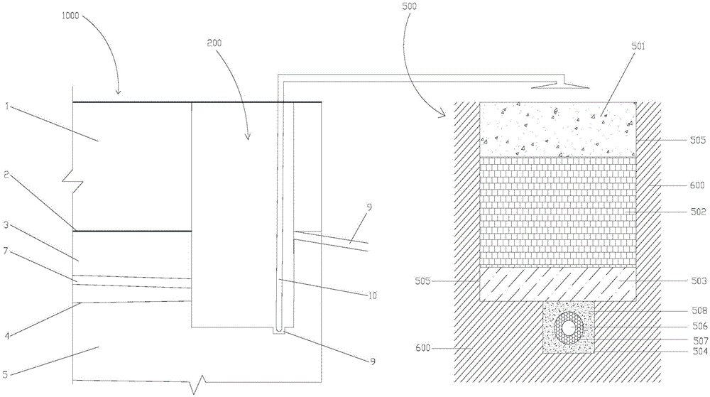
Referring to fig. 1-2, the system for collecting rainwater and improving saline-alkali soil in saline-alkali soil of the present invention comprises a saline-alkali soil water resource collecting system 1000 and a saline-alkali soil improving system 500;
the saline-alkali soil water resource collection system 1000 comprises a soil body 100 and a storage and drainage well 200; the soil body 100 comprises a first planting soil layer 1, a permeable membrane layer 2, a water storage layer 3, a waterproof layer 4 and a saline-alkali soil layer 5 which are arranged in sequence from top to bottom; the lower surface of the water storage layer 3 is provided with a groove 6 which protrudes into the saline-alkali soil layer, and a hidden pipe 7 is arranged in the groove 6; the hidden pipe 7 is connected and communicated with the storage and discharge well 200 in the slope direction; the storage and drainage wells 200 are arranged in the soil body 100 at intervals, the depth of the storage and drainage wells extends to the lower part of the groove 6 from top to bottom, and the well wall of the part of the storage and drainage wells 200, which is in contact with the aquifer 3, is of a seepage pipe structure so as to meet the dual functions of air exhaust and water seepage; the other part of the well wall is of a watertight structure, and a lateral waterproof layer is adopted for reverse wrapping at the joint of the saline-alkali soil water resource collecting system 1000 and the surrounding buildings or structures; an overflow drain pipe 8 is arranged on the storage and drainage well wall, and the overflow drain pipe 8 is flush with the lower surface of the first planting soil layer 1; a water taking pit 9 is arranged at the bottom of the storage and discharge well 200, and a water taking pipe 10 is arranged at the wellhead of the storage and discharge well 200 and extends into the water taking pit 9;
the saline-alkali soil improvement system 500 comprises a large pit dug in saline-alkali soil 600, wherein a second planting soil layer 501, an original soil layer 502, a salt discharge layer 503, a salt discharge ditch 504 and an isolation layer 505 are arranged in the large pit from top to bottom;
an isolation layer 505 is arranged in the large pit, and the isolation layer 505 is paved on all side walls of the pit, the bottom of the pit and the salt discharge trench 504;
the salt discharge ditch 504 is arranged at the bottom of the pit, a drain pipe 506 is arranged in the salt discharge ditch 504, and coarse sand 507 with the thickness of 4-6cm and fine sand 508 with the thickness of 8-12cm are coated around the drain pipe 506 or permeable geotextile is coated; the coarse sand 507 and the fine sand 508 are coated outside the pipe, or the permeable geotextile can play a role in water permeation and prevent silt from entering a drain pipe to cause blockage; the outlet of the drain pipe leads to a municipal drainage well; the grain size of the coarse sand 507 is 0.5-2 mm; the grain size of the fine sand 508 is 0.25-0.4 mm;
a salt discharge layer 503 is arranged above the pit bottom isolation layer 505 and the salt discharge ditch 504; an original soil layer 502 is arranged above the salt discharging layer 503; a second planting soil layer 501 is arranged above the original soil layer 502;
the outlet of the water intake pipe 10 is arranged above the second planting soil layer.
Saline and alkaline land improvement system 500 is in the high and great area of water level variation irregularity or fluctuation of groundwater mineralization, for guaranteeing greening plant's normal growth, has adopted the method that physical isolation measure and salt elimination measure combined together, avoids the invasion of groundwater to the soil body to the at utmost.
The utility model discloses a theory of operation is:
in the raining process, rainwater on the surface of the saline-alkali soil water resource collecting system 1000 is firstly filtered through the first planting soil layer 1, then enters the water storage layer 3 after passing through the water permeable membrane layer 2, is collected into the groove 6 after being filtered, and is conveyed to the storage and drainage well 200 through the concealed pipe 7 to be stored;
meanwhile, in the rainy process, the saline-alkali soil improvement system 500 firstly filters through the second planting soil layer 501 and washes the original soil layer, takes away partial salt, then enters the salt discharging layer 503, then is collected in the salt discharging ditch 504, and then is conveyed to a municipal drainage well through the drainage pipe 506 to be discharged;
when the saline-alkali soil does not rain, rainwater stored in the storage and drainage well 200 of the saline-alkali soil water resource collection system 1000 is conveyed to the upper part of the upper part 501 of the second planting soil layer of the saline-alkali soil improvement system 500 through the water intake pipe 10, and the upper part 501 of the second planting soil layer is continuously flushed, so that salt in the original soil layer 502 is continuously taken away; the sprinkling mode can be sprinkling irrigation, drip irrigation and micro-sprinkling.
Therefore, the utility model discloses abundant utilization the rainwater of rainfall in-process and the rainwater that the rainfall in-process storage was filed improve saline and alkaline soil original soil layer, avoided the waste of water resource, also can not lead to the production of salt phenomenon again.
According to certain preferred embodiments of the present invention, the first planting soil layer 1 has a thickness of 60 to 140 cm.
According to certain preferred embodiments of the present invention, the permeable membrane layer 2 is a permeable nonwoven fabric.
According to certain preferred embodiments of the present invention, the aquifer 3 is a large pore material such as 18-60cm thick stone chips or crushed stone or pp modules.
According to some preferred embodiments of the present invention, the waterproof layer 4 comprises an upper waterproof geotextile layer, a first waterproof membrane layer and a lower waterproof geotextile layer, and extends to the bottom of the well at the overflow water taking and draining well 200; the waterproof layer 4 is arranged, so that rainwater can be guaranteed to be drained into the storage and drainage well 200 through the concealed pipe 7 after penetrating into the water storage layer 3, and the rainwater cannot directly penetrate into the saline-alkali soil layer 5 below to be lost; the saline water in the saline-alkali soil layer 5 can be ensured not to reversely permeate into the water storage layer 3, even reversely permeate into the planting soil layer 1, so that the planting soil layer 1 is damaged; the waterproof layer 4 also isolates the mutual water seepage problem between the water storage layer 3 and the saline-alkali soil layer 5 at the position of the storage and drainage well; in addition, the upper waterproof geotextile layer is also helpful for enhancing the toughness and strength of the waterproof layer and preventing the waterproof membrane layer from being damaged by broken stones and the like on the upper layer; also, the lower waterproof geotechnical layer helps to prevent damage to the first waterproof membrane layer by the lower saline-alkali soil layer 5.
According to certain preferred embodiments of the present invention, the concealed pipes 7 are arranged every 6-8 meters; the concealed pipe 7 is a PVC seepage pipe and is communicated with the storage and discharge well 200 in a 2% slope direction; in order to prevent the blind pipe from being blocked by the seepage hole, the blind pipe is coated with a permeable geotextile; the utility model discloses can open out the narrow shape infiltration hole of multirow on the hidden pipe 7 circumference, can be through controlling the aperture ratio, satisfy different ring rigidity and permeability requirement; the underground pipe 7 is coated with the permeable geotextile, so that the water permeating effect can be achieved, and the blockage caused by the silt entering the underground pipe 7 can be avoided.
According to certain preferred embodiments of the present invention, when the green space is very large, the saline-alkali land water resource collection system can be divided into a plurality of catchment areas for easy management and control, and the different catchment areas can be separated by reverse wrapping with waterproof geotextile; the height of the turn-up is typically more than 50cm above the crushed stone layer (not shown).
According to certain preferred embodiments of the present invention, the depth of the drainage wells 200 extends to at least 1m below the trench 6.
According to certain preferred embodiments of the present invention, the depth of the large pit is 0.6-1.5 m (if the groundwater level is high, the depth can be shortened according to actual conditions).
According to certain preferred embodiments of the present invention, the isolation layer 505 includes an inner waterproof geotextile layer, a second waterproof membrane layer, and an outer waterproof geotextile layer. The isolation layer 505 can ensure that water permeates into the saline-alkali soil layer below and is lost; the saline water in the saline-alkali soil layer can be prevented from reversely permeating into the large pit and even reversely permeating into the planting soil layer 501, so that the planting soil layer 501 is damaged; in addition, the inner waterproof geotextile layer is also beneficial to enhancing the toughness and strength of the isolation layer 505 and preventing broken stones and the like from damaging the isolation layer 505; likewise, the outer waterproof geotechnical layer also helps prevent damage to the barrier 505 from the saline-alkali soil outside the large pit.
According to certain preferred embodiments of the present invention, the salt discharge ditches 504 are spaced at the bottom of the pit, with a spacing of 6-8 m, and a width and a depth of 25-45 cm.
According to certain preferred embodiments of the present invention, the drain pipe 506 is a PVC seepage pipe; more preferably, a plurality of rows of narrow-strip-shaped water seepage holes can be formed on the circumference of the water drainage pipe 506, and the requirements of different ring rigidity and permeability can be met by controlling the opening rate.
According to certain preferred embodiments of the present invention, the salt-removing layer 503 is stone chips or grit with a thickness of 15-22 cm; the particle size of the stone chips or coarse sand is 0.5-10 mm.
According to some preferred embodiments of the present invention, the raw soil layer 502 is raw saline-alkali soil crushed particles having a thickness of 50 to 80 cm; preferably, modifying agents can be mixed into the original soil layer 502 according to needs; generally speaking, modifiers such as organic fertilizers, turfy soil, mountain leather sand and the like are mostly adopted for improving the prior saline-alkali soil; preferably, the modifier used in the present invention comprises subcritical hydrolyzed sludge, subcritical hydrolyzed chicken manure, composite bacterial manure and fiber adhesive (all existing commodities, such as subcritical hydrolyzed sludge and subcritical hydrolyzed chicken manure produced by shanghai span long environmental protection member company, the composite bacterial manure is a composite microbial manure commodity produced by Weifang Shenzhou biofertilizer Co., Ltd., and the fiber adhesive is a soil fiber adhesive commodity produced by river south China Roots chemical products, trade Co., Ltd.).
The mass ratio of the subcritical hydrolyzed sludge to the subcritical hydrolyzed chicken manure to the composite bacterial fertilizer to the fiber adhesive is 5-15: 1-3: 20-50: 100-150.
Experiments show that the modifier of the utility model has improved improvement effect by 50-100% compared with the prior conventional saline-alkali soil modifier such as organic fertilizer, turfy soil and mountain skin sand.
According to certain preferred embodiments of the present invention, the planting soil layer 501 has a thickness of 40-50 cm; various plants 509 can be planted on the planting soil layer.
The saline-alkali soil water resource collecting system 1000 and the saline-alkali soil improving system 500 of the utility model are mutually matched, so that the improvement efficiency is excellent; 1) the saline-alkali soil water resource collection system 1000 is not only a rainwater collection system, but also an improvement means of saline-alkali soil, and has double functions; 2) the usable rainwater of saline and alkaline land improvement system 500 improves the native soil horizon of self during the rainwater, when not rainfall, can utilize the rainwater of saline and alkaline land water resource collection system 1000 collection again to improve, and the water resource has obtained make full use of.
It is obvious that the above embodiments of the present invention are only examples for clearly illustrating the present invention, and are not limitations to the embodiments of the present invention. Other variations and modifications will be apparent to persons skilled in the art in light of the above description. Not all embodiments are exhaustive. All obvious changes or variations led out by the technical scheme of the utility model are still in the protection scope of the utility model.