CN212268767U - Feeding mechanism - Google Patents
Feeding mechanism Download PDFInfo
- Publication number
- CN212268767U CN212268767U CN202021104436.2U CN202021104436U CN212268767U CN 212268767 U CN212268767 U CN 212268767U CN 202021104436 U CN202021104436 U CN 202021104436U CN 212268767 U CN212268767 U CN 212268767U
- Authority
- CN
- China
- Prior art keywords
- groove
- limiting
- limiting groove
- feeding mechanism
- stopper
- Prior art date
- Legal status (The legal status is an assumption and is not a legal conclusion. Google has not performed a legal analysis and makes no representation as to the accuracy of the status listed.)
- Active
Links
- 238000009434 installation Methods 0.000 description 8
- 238000000034 method Methods 0.000 description 4
- 238000010586 diagram Methods 0.000 description 2
- 238000005299 abrasion Methods 0.000 description 1
- 230000009286 beneficial effect Effects 0.000 description 1
- 230000002093 peripheral effect Effects 0.000 description 1
Images




Landscapes
- Warehouses Or Storage Devices (AREA)
Abstract
The utility model discloses a feed mechanism, include: the material rack is provided with a material groove for placing materials; the driving assembly is matched with the material rack and used for pushing the materials to move in the material groove; and the limiting assembly is matched with the material rack and used for limiting the materials to move out of the material groove. The utility model provides a feed mechanism carries out orderly the piling up with the balancing pole through the material groove, carries out orderly material loading through drive assembly to the balancing pole, blocks the balancing pole through spacing subassembly, prevents that the balancing pole from dropping, provides higher material loading efficiency for subsequent assembly.
Description
Technical Field
The utility model belongs to the technical field of automatic material loading, concretely relates to feed mechanism.
Background
The balancing rod is an important part on the keyboard, the diameter of the balancing rod is very small, the balancing rod corresponds to different keycaps, the lengths of the balancing rods are different, and the balancing rod is assembled manually in the traditional assembling process and is very troublesome; at present, automatic equipment is also adopted for assembly, but due to the size problem of the balance bar, the balance bar is very easy to drop or clamp in the conveying process, so that subsequent assembly is influenced, and therefore the automatic equipment capable of efficiently conveying the balance bar is difficult to appear in the market.
Therefore, in order to solve the above technical problems, it is necessary to provide a feeding mechanism.
SUMMERY OF THE UTILITY MODEL
In view of this, the present invention provides a feeding mechanism to realize high-efficiency balance bar feeding for subsequent assembly.
In order to achieve the above object, an embodiment of the present invention provides the following technical solutions:
a feed mechanism, comprising:
the material rack is provided with a material groove for placing materials;
the driving assembly is matched with the material rack and used for pushing the materials to move in the material groove;
and the limiting assembly is matched with the material rack and used for limiting the materials to move out of the material groove.
In one embodiment, the material rack comprises a bottom plate, and a first stop block and a second stop block which are arranged on the bottom plate.
In one embodiment, a first limiting groove is formed in one side of the first stop, a second limiting groove is formed in one side of the second stop, the first limiting groove and the second limiting groove are oppositely arranged, and a material groove is defined by the first limiting groove and the second limiting groove.
In an embodiment, the first limiting groove is provided with a first protrusion, and the second limiting groove is provided with a second protrusion.
In an embodiment, the bottom plate is provided with a first waist-shaped hole for being mounted with the first stopper and a second waist-shaped hole for being mounted with the second stopper.
In one embodiment, the driving assembly comprises a first air cylinder arranged at the bottom of the material rack and a push block which is positioned in the material groove and is installed in a matching manner with the first air cylinder.
In one embodiment, the limiting assembly comprises a plurality of second air cylinders arranged on the side edge of the top of the material tank and limiting parts arranged on the second air cylinders.
In one embodiment, two second air cylinders are respectively arranged on two sides of the top of the material groove.
Compared with the prior art, the utility model has the advantages of it is following:
the utility model provides a feed mechanism carries out orderly the piling up with the balancing pole through the material frame, carries out orderly material loading through drive assembly to the balancing pole, blocks the balancing pole through spacing subassembly, prevents that the balancing pole from dropping, provides higher material loading efficiency for subsequent assembly.
Drawings
In order to more clearly illustrate the embodiments of the present application or the technical solutions in the prior art, the drawings needed to be used in the description of the embodiments or the prior art will be briefly described below, it is obvious that the drawings in the following description are only some embodiments described in the present application, and other drawings can be obtained by those skilled in the art without creative efforts.
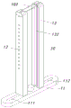
Fig. 1 is a schematic structural view of a feeding mechanism in an embodiment of the present invention;
fig. 2 is a schematic structural view of a material shelf according to an embodiment of the present invention;
fig. 3 is a top view of the material shelf according to an embodiment of the present invention;
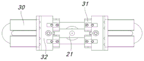
fig. 4 is a top view of a feeding mechanism according to an embodiment of the present invention;
fig. 5 is a first schematic structural diagram of a mounting block according to an embodiment of the present invention;
fig. 6 is a schematic structural diagram of a mounting block according to an embodiment of the present invention.
Detailed Description
The present invention will be described in detail below with reference to embodiments shown in the drawings. However, the present invention is not limited to the embodiments, and the structural, method, or functional changes made by those skilled in the art according to the embodiments are all included in the scope of the present invention.
Referring to fig. 1, the feeding mechanism in one embodiment of the present invention includes:
the material rack 10 is provided with a material groove for placing a balancing pole, wherein the material groove is formed in the material rack 10;
the driving assembly is matched with the material rack and used for pushing the balancing rod to move in the material groove;
and the limiting assembly is matched with the material rack and used for limiting the balance rod to move out of the material groove.
The components in the present embodiment will be described in detail below with reference to the drawings.
Referring to fig. 1 in conjunction with fig. 2, a material tank is provided on the material shelf 10, and a balance bar 100 is placed through the material tank.
Specifically, the material rack 10 includes a bottom plate 11, and a first stopper 12 and a second stopper 13 which are installed on the bottom plate 11, used for limiting the moving direction of the balancing bar 100, and have an adjustable distance therebetween, and both the first stopper 12 and the second stopper 13 are strip-shaped and vertically fixed on the bottom plate 11.
Referring to fig. 3 and being combined with fig. 2, a first limiting groove 121 is arranged on one side of the first stopper 12, a second limiting groove 131 is arranged on one side of the second stopper 13, the first limiting groove 121 and the second limiting groove 131 are oppositely arranged, a material groove is defined by the first limiting groove 121 and the second limiting groove 131, the first limiting groove 121 is used for accommodating one end of the balance bar 100, the second limiting groove 131 is used for accommodating the other end of the balance bar 100, the balance bar 100 is stacked in the material groove one by one, and the balance bar 100 is limited to move in the peripheral direction through the material groove.
In this implementation, referring to fig. 3, a first protruding portion 122 is disposed in the first limiting groove 121, a second protruding portion 132 is disposed in the second limiting groove 131, the balancing bar 100 is placed in the material groove, two ends of the balancing bar 100 are respectively in contact with the first protruding portion 122 and the second protruding portion 132, and the two ends of the balancing bar 100 are directly in contact with the first limiting groove 121 and the second limiting groove 131 through the arrangement of the first protruding portion 122 and the second protruding portion 132, so that the contact area is greatly reduced, and the abrasion of the balancing bar 100 in the moving process is reduced.
In this embodiment, referring to fig. 2 and fig. 3, a first waist-shaped hole 111 for being installed with the first stopper 12 and a second waist-shaped hole 112 for being installed with the second stopper 13 are provided on the bottom plate 11, the first stopper 12 and the second stopper 13 are fixed by fixing members such as bolts through the first waist-shaped hole 111 and the second waist-shaped hole 112, the first waist-shaped hole 111 and the second waist-shaped hole 112 are both long strips, and the distance between the first stopper 12 and the second stopper 13 can be adjusted by moving the first stopper 12 and the second stopper 13 to adapt to the balance bars 100 with different lengths through the lengths of the first waist-shaped hole 111 and the second waist-shaped hole 112.
Referring to fig. 1, a driving assembly is installed to cooperate with the material shelf 10 for driving the balancing bar 100 to move in the material chute.
Specifically, the driving assembly comprises a first air cylinder 20 installed at the bottom of the material rack 10 and a push block 21 located in the material groove and installed in cooperation with the first air cylinder 20, the first air cylinder 20 is installed at the bottom of the bottom plate 11, two ends of the push block 21 are respectively in contact with the first protruding portion 122 and the second protruding portion 132, an expansion rod of the first air cylinder 20 penetrates through the bottom plate 11 to be fixed with the push block 21, and the first air cylinder 20 drives the push block 21 to move up and down in the material groove so as to drive the balance rod 100 in the material groove to move up and down.
Referring to fig. 1, a limiting assembly is installed in cooperation with the material shelf 10 to limit the movement of the balancing bar 100 out of the material groove.
Referring to fig. 1 and fig. 4, the limiting assembly includes a plurality of second cylinders 30 installed at the side of the top of the material tank, and a limiting member 31 installed on the second cylinders 30, two second cylinders 30 are respectively installed at two sides of the top of the material tank, wherein the two second cylinders 30 are installed at the top of the first stopper 12, the other two second cylinders 30 are installed at the top of the second stopper 13, the limiting member 31 is flat, and the limiting member 31 is pushed out by the second cylinders 30 to block the balance bar 100, so as to prevent the balance bar 100 from moving out and falling.
In this embodiment, referring to fig. 1 and fig. 5, an installation block 32 for installing the second cylinder 30 is disposed on a side edge of the top of the material tank, the installation blocks 32 are installed on the first stopper 12 and the second stopper 13, an installation groove 321 for fixing the installation block 32 and a guide groove 322 for moving the limiting member 31 are disposed on one side of the installation block 32, a first through hole 323 for moving the telescopic rod of the second cylinder 30 and communicating with the guide groove 322 is disposed on the other side of the installation block 32, and an installation hole 324 for installing the body of the second cylinder 30 and communicating with the first through hole 323 and the guide groove 322 is disposed on the other side of the installation block 32.
When the balance bar 100 needs to be loaded, the first air cylinder 20 drives the push block 21 to move upwards so as to push the balance bar 100 to move upwards and move out of the material groove, and when the balance bar 100 does not need to be loaded, the second air cylinder 30 pushes the limiting piece 31 to extend out so as to block the balance bar 100, so that the balance bar 100 is prevented from moving out and falling.
According to the technical scheme provided by the utility model, the utility model discloses following beneficial effect has:
the utility model provides a feed mechanism carries out orderly the piling up with the balancing pole through the material frame, carries out orderly material loading through drive assembly to the balancing pole, blocks the balancing pole through spacing subassembly, prevents that the balancing pole from dropping, provides higher material loading efficiency for subsequent assembly.
It is obvious to a person skilled in the art that the invention is not restricted to details of the above-described exemplary embodiments, but that it can be implemented in other specific forms without departing from the spirit or essential characteristics of the invention. The present embodiments are therefore to be considered in all respects as illustrative and not restrictive, the scope of the invention being indicated by the appended claims rather than by the foregoing description, and all changes which come within the meaning and range of equivalency of the claims are therefore intended to be embraced therein. Any reference sign in a claim should not be construed as limiting the claim concerned.
Furthermore, it should be understood that although the present description refers to embodiments, not every embodiment may contain only a single embodiment, and such description is for clarity only, and those skilled in the art should integrate the description, and the embodiments may be combined as appropriate to form other embodiments understood by those skilled in the art.
Claims (8)
1. A feed mechanism, characterized in that, feed mechanism includes:
the material rack is provided with a material groove for placing materials;
the driving assembly is matched with the material rack and used for pushing the materials to move in the material groove;
and the limiting assembly is matched with the material rack and used for limiting the materials to move out of the material groove.
2. The loading mechanism of claim 1, wherein the material holder comprises a base plate and first and second stops mounted on the base plate.
3. The feeding mechanism according to claim 2, wherein a first limiting groove is formed on one side of the first stop, a second limiting groove is formed on one side of the second stop, the first limiting groove and the second limiting groove are oppositely arranged, and the first limiting groove and the second limiting groove are enclosed to form a material groove.
4. The feeding mechanism according to claim 3, wherein a first protrusion is disposed in the first limiting groove, and a second protrusion is disposed in the second limiting groove.
5. The feeding mechanism as claimed in claim 2, wherein the bottom plate is provided with a first waist-shaped hole for being mounted with the first stopper and a second waist-shaped hole for being mounted with the second stopper.
6. The feeding mechanism according to claim 1, wherein the driving assembly comprises a first air cylinder arranged at the bottom of the material frame and a pushing block which is positioned in the material groove and is matched with the first air cylinder.
7. The feeding mechanism according to claim 1, wherein the limiting assembly comprises a plurality of second air cylinders arranged on the side edge of the top of the material groove and a limiting member arranged on the second air cylinders.
8. The feeding mechanism according to claim 7, wherein two second air cylinders are respectively arranged on two sides of the top of the material groove.
Priority Applications (1)
| Application Number | Priority Date | Filing Date | Title |
|---|---|---|---|
| CN202021104436.2U CN212268767U (en) | 2020-06-15 | 2020-06-15 | Feeding mechanism |
Applications Claiming Priority (1)
| Application Number | Priority Date | Filing Date | Title |
|---|---|---|---|
| CN202021104436.2U CN212268767U (en) | 2020-06-15 | 2020-06-15 | Feeding mechanism |
Publications (1)
| Publication Number | Publication Date |
|---|---|
| CN212268767U true CN212268767U (en) | 2021-01-01 |
Family
ID=73882587
Family Applications (1)
| Application Number | Title | Priority Date | Filing Date |
|---|---|---|---|
| CN202021104436.2U Active CN212268767U (en) | 2020-06-15 | 2020-06-15 | Feeding mechanism |
Country Status (1)
| Country | Link |
|---|---|
| CN (1) | CN212268767U (en) |
Cited By (1)
| Publication number | Priority date | Publication date | Assignee | Title |
|---|---|---|---|---|
| CN111591747A (en) * | 2020-06-15 | 2020-08-28 | 吴江亿韦机电科技有限公司 | Feeding mechanism |
-
2020
- 2020-06-15 CN CN202021104436.2U patent/CN212268767U/en active Active
Cited By (1)
| Publication number | Priority date | Publication date | Assignee | Title |
|---|---|---|---|---|
| CN111591747A (en) * | 2020-06-15 | 2020-08-28 | 吴江亿韦机电科技有限公司 | Feeding mechanism |
Similar Documents
| Publication | Publication Date | Title |
|---|---|---|
| CN106077259A (en) | Integrated motor shell punch forming device | |
| CN214059049U (en) | Battery pack conveying tool | |
| CN217806966U (en) | Battery cell stepping carrying device | |
| CN115449737B (en) | A strip straightening assembly for auxiliary diode intrusion tin charging jig | |
| CN222573557U (en) | Magnet arrangement combined feeding mechanism | |
| CN108861464B (en) | Integrated discharging bin mechanism | |
| CN115528873A (en) | Magnetic tile assembly machine | |
| CN111834688B (en) | Battery cell release and recovery assembly line | |
| CN112172019B (en) | Distributing type loading attachment of rubber coating injection molding machine | |
| CN211361168U (en) | Welding fixture for intelligent terminal mainboard | |
| CN219859180U (en) | Electric core cartridge clip feed mechanism | |
| CN214411011U (en) | Key cap balancing pole kludge | |
| CN220652302U (en) | Electric core annotates liquid needle guiding mechanism | |
| CN215885459U (en) | Double-station material taking mechanism | |
| CN215239059U (en) | Part leading-in mechanism for assembling lighter | |
| CN213796898U (en) | FPC general purpose exhaust device | |
| CN214290572U (en) | Electronic component processing device | |
| CN210132264U (en) | Battery mesh cutting rack | |
| CN216706311U (en) | Laser marking machine that work efficiency is high | |
| CN219106230U (en) | Battery cell secondary electrode folding earphone structure | |
| CN219959279U (en) | Cabinet brackets, battery cabinets and energy storage containers | |
| CN207577806U (en) | A kind of automatic feed mechanism of long bolt | |
| CN220739098U (en) | Hydraulic bending machine | |
| CN221447664U (en) | Wire harness positioning mechanism for processing electronic wire harness | |
| CN217920172U (en) | Disc feeding mechanism |
Legal Events
| Date | Code | Title | Description |
|---|---|---|---|
| GR01 | Patent grant | ||
| GR01 | Patent grant |