CN212267151U - Taper pin cooperation steering axle front axle assembly - Google Patents
Taper pin cooperation steering axle front axle assembly Download PDFInfo
- Publication number
- CN212267151U CN212267151U CN202022131779.4U CN202022131779U CN212267151U CN 212267151 U CN212267151 U CN 212267151U CN 202022131779 U CN202022131779 U CN 202022131779U CN 212267151 U CN212267151 U CN 212267151U
- Authority
- CN
- China
- Prior art keywords
- assembly
- main pin
- steering knuckle
- pin
- front shaft
- Prior art date
- Legal status (The legal status is an assumption and is not a legal conclusion. Google has not performed a legal analysis and makes no representation as to the accuracy of the status listed.)
- Active
Links
- 125000006850 spacer group Chemical group 0.000 claims abstract description 22
- 238000007789 sealing Methods 0.000 claims abstract description 12
- 230000007704 transition Effects 0.000 claims description 5
- 230000002035 prolonged effect Effects 0.000 abstract description 7
- 238000005299 abrasion Methods 0.000 abstract description 6
- 238000010276 construction Methods 0.000 abstract description 3
- 238000004519 manufacturing process Methods 0.000 abstract description 3
- 238000000034 method Methods 0.000 abstract description 3
- 239000003921 oil Substances 0.000 description 10
- 230000000712 assembly Effects 0.000 description 1
- 238000000429 assembly Methods 0.000 description 1
- 230000002146 bilateral effect Effects 0.000 description 1
- 230000007812 deficiency Effects 0.000 description 1
- 239000010687 lubricating oil Substances 0.000 description 1
- XLYOFNOQVPJJNP-UHFFFAOYSA-N water Substances O XLYOFNOQVPJJNP-UHFFFAOYSA-N 0.000 description 1
Images

Landscapes
- Steering-Linkage Mechanisms And Four-Wheel Steering (AREA)
Abstract
A taper pin matched steering axle front axle assembly is mainly used for a chassis steering axle front axle structure of an engineering vehicle. The main pin hole of the front shaft is a taper hole, the main pin is in a taper pin structure, and the main pin and the front shaft are in a taper matching structure. The utility model adopts the low-fall front axle, which can increase the ground clearance of the chassis, thereby satisfying the requirement of high trafficability of the whole vehicle in the construction site; the front shaft is matched with the main pin by adopting a conical surface, and a lock pin structure is avoided, so that the processing procedures of lock pins and lock pin holes are reduced, the production cost is reduced, the stress level of the main pin holes is improved, and the service life of the front shaft is prolonged; the taper matching of the main pin and the front shaft is realized through a pre-tightening nut at the tail part of the small end of the main pin, and the assembly and disassembly are convenient and easy to maintain; the spacer bush structure can provide a binding surface for the pre-tightening nut, improve the abrasion of the small end of the main pin and increase the durability of the main pin; the steering knuckle assembly bushing mounting hole is internally provided with a main pin oil seal structure, so that the sealing performance in the bushing hole can be effectively improved, the abrasion of the bushing and the main pin is reduced, and the service life is prolonged.
Description
Technical Field
The utility model relates to an automobile chassis spare part technical field specifically is a taper pin cooperation steering axle front axle assembly for machineshop car.
Background
In recent years, due to the needs of infrastructure engineering, the demands of engineering vehicles are more and more, the loads of the engineering vehicles are large, the running road surfaces are mostly uneven and muddy water, and the quality of the road surfaces is poor, so that the running working conditions of the engineering vehicles are quite bad, and the failure rate of the existing engineering vehicles is obviously higher than that of road vehicles according to early market failure analysis. Therefore, aiming at the severe working conditions of the engineering truck, it is necessary to research a steering axle front axle assembly capable of greatly improving the service life mileage of the engineering truck.
Disclosure of Invention
For overcoming the deficiencies of the prior art, the invention aims to provide a taper pin cooperation steering axle front axle assembly to satisfy the driving demand of engineering vehicles under the severe working conditions such as construction sites.
In order to realize the purpose, the left end and the right end of the front shaft of the utility model are provided with a steering knuckle assembly, a main pin is arranged in a main pin hole at the left end and the right end of the front shaft, the steering knuckle assembly is fastened with a brake bottom plate of a brake assembly through a bolt, a wheel end assembly is arranged and positioned at the rod part of the steering knuckle assembly through a hub inner bearing, a hub outer bearing and a lock nut, an adjusting gasket is arranged between the steering knuckle assembly and the upper end surface of the main pin hole of the front shaft, a thrust bearing is arranged between the steering knuckle assembly and the lower end surface of the main pin hole of the front shaft, the upper part of the steering knuckle assembly is provided with an air chamber bracket and a drag link arm, the air chamber bracket is provided with an air chamber, a push rod of the air chamber is in revolute pair fit; a left steering knuckle arm and a right steering knuckle arm are arranged on the inner sides of the lower parts of the left steering knuckle assembly and the right steering knuckle assembly, a tie rod assembly is arranged between the left steering knuckle arm and the right steering knuckle arm and is respectively connected with the left steering knuckle arm and the right steering knuckle arm in a ball pair manner, and a front shaft, the left steering knuckle arm, the right steering knuckle arm and the tie rod assembly form a steering trapezoid to realize the steering function of a front wheel; the main pin hole of the front shaft is a taper hole, the main pin is of a taper pin structure, and the main pin and the front shaft are of a taper matching structure.
The taper fit of the main pin and the front shaft is realized by applying an axial force through a pre-tightening nut at the tail part of the small end of the main pin, the main pin is tightly matched with a main pin hole of the front shaft, an outer cylindrical surface of the small end of the main pin is in transition fit with an inner hole surface of a spacer bush, an outer cylindrical surface of the spacer bush is in clearance fit with an inner hole of an upper bushing of a steering knuckle assembly, the spacer bush is of an inverted cup-shaped structure, the large end of the main pin is in clearance fit with a lower bushing of the steering knuckle assembly, the upper end surface of the spacer bush is provided with a hole, a thread through hole at the small end of the main pin penetrates out and then is matched with the pre-tightening nut, a flange surface of the pre-tightening nut is attached to the upper end surface of the spacer bush after the.
An upper main pin oil seal and a lower main pin oil seal are respectively arranged in mounting holes of an upper bushing and a lower bushing of the steering knuckle assembly, a sealing plug cover, a clamp spring and an oil nozzle are arranged at the lower part of the steering knuckle assembly, and the clamping spring fixes the sealing plug cover in a counter bore at the lower part of the steering knuckle assembly.
Except that the right half of the front axle assembly is provided with no drag link arm, the other structures are completely symmetrical with the left half structure.
Compared with the prior art, the utility model adopts the low-fall front axle, which can increase the ground clearance of the chassis, thereby meeting the requirement of high trafficability of the whole vehicle in the construction site; the front shaft is matched with the main pin by adopting a conical surface, and a lock pin structure is avoided, so that the processing procedures of lock pins and lock pin holes are reduced, the production cost is greatly reduced, the stress level of the main pin holes is improved, and the service life of the front shaft is prolonged; the taper matching of the main pin and the front shaft is realized through a pre-tightening nut at the tail part of the small end of the main pin, and the structure is convenient to assemble and disassemble and easy to maintain; the spacer bush structure can provide a binding surface for the pre-tightening nut, meanwhile, the small end abrasion of the main pin is improved, and the durability of the main pin is improved; the upper and lower bushing mounting holes of the knuckle assembly are respectively provided with a main pin oil seal structure, so that the sealing performance in the bushing hole can be effectively improved, the abrasion of the bushing and the main pin is reduced, and the service life is prolonged.
Drawings
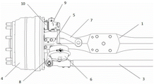
Fig. 1 is a schematic view of the present invention.
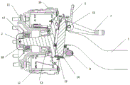
Fig. 2 is a top view of fig. 1.
Fig. 3 is a cross-sectional view of fig. 1.
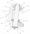
Fig. 4 is a partially enlarged view of fig. 3.
In the figure: 1. a front axle; 2. a knuckle assembly; 3. a tie rod assembly; 4. a hub assembly; 5. an air chamber support; 6. an air chamber; 7. a straight pull rod arm; 8. a left knuckle arm; 9. an adjusting arm; 10. a camshaft; 11. a hub and brake drum assembly; 12. a brake assembly; 13. a hub inner bearing; 14. a kingpin; 15. a spacer sleeve; 16. pre-tightening the nut; 17. a hub outer bearing; 18. a lock nut; 19. a thrust bearing; 20. a nozzle tip; 21. an upper bushing; 22. a lower bushing; 23. adjusting the gasket; 24. sealing the plugging cover; 25. a clamp spring; 26. a lower king pin oil seal; 27. and (4) oil sealing of the upper main pin.
Detailed Description
As shown in fig. 1, 2, 3 and 4, all the drawings of the present invention are the left half structure of the front axle assembly of the steering axle, and the other parts of the right half structure are completely identical and symmetrical to the left half structure except for the right half without the tie rod arm 7. Front axle 1 is the main supporting body of this assembly, front axle 1 bilateral symmetry, both ends are for having the "fist" structure of king pin hole, "the" curved neck "structure of smooth and smooth transition between" fist "and the plate spring seat, control the middle" I "structure that is of plate spring seat, through reducing the difference in height between" fist "and the plate spring seat plane, optimize" curved neck "transition zone circular arc simultaneously to can effectively reduce the one-level drop of front axle. The primary fall of the front axle 1 is 60mm, compared with the existing product, the ground clearance of the whole vehicle is obviously improved, and the trafficability characteristic of the vehicle is improved; the main pins 14 are arranged in the main pin holes at the left end and the right end of the front shaft 1, the main pins 14 are used for installing and positioning the steering knuckle assembly 2 on one hand, and provide a rotation center for the steering knuckle assembly 2 on the other hand, the main pin holes of the front shaft 1 are taper holes, the main pins 14 are taper pin structures, the main pins 14 and the front shaft 1 are in taper fit structures, and no lock pin holes or lock pin structures are arranged, so that the processing procedures of the front shaft 1 can be effectively reduced, the manufacturing cost is reduced, the stress level of the main pin holes is improved, and the service life of the front shaft 1 is prolonged; the outer cylindrical surface of the small end of the main pin 14 is in transition fit with the inner hole surface of the spacer sleeve 15, the outer cylindrical surface of the spacer sleeve 15 is in clearance fit with the inner hole of the upper bushing 21 of the steering knuckle assembly 2, the spacer sleeve 15 is in an inverted cup-shaped structure, the upper end surface of the spacer sleeve 15 is provided with a hole, the tail part of the small end of the main pin 14 is provided with a thread, the main pin 14 is in tight fit with the main pin hole of the front shaft 1, the thread of the small end of the main pin 14 penetrates through the hole of the spacer sleeve 15 and then is matched with the pre-tightening nut 16, the flange surface of the pre-tightening nut 16 is attached to the upper end surface of the spacer sleeve 15 after being tightened, the pre-tightening nut 16 provides an upward axial force for the main pin 14 after being tightened, so that the main pin 14 and the front shaft 1 are extruded and the purpose of tight fit is achieved, the main pin 14 and the front shaft 1 are matched by applying an axial force to the pre-tightening nut 16 at the tail part of the small end of the main pin 14, the structure is convenient and easy to maintain, the service life of the front shaft 1 is prolonged, the structure of the spacer bush 15 can provide a binding surface for the pre-tightening nut 16, meanwhile, the small end abrasion of the main pin 14 is improved, and the durability of the main pin 14 is improved; the big end of the main pin 14 is in clearance fit with a lower bushing 22 of the knuckle assembly 2, the lower edge of the spacer sleeve 15 is attached to an adjusting gasket 23, the adjusting gasket 23 is arranged between the knuckle assembly 2 and the upper end face of the main pin hole of the front shaft 1, and a thrust bearing 19 is arranged between the knuckle assembly 2 and the lower end face of the main pin hole of the front shaft 1. The left end and the right end of the front shaft 1 are provided with the knuckle assembly 2, the mounting holes of an upper bushing 21 and a lower bushing 22 of the knuckle assembly 2 are respectively provided with an upper main pin oil seal 27 and a lower main pin oil seal 26, the lower part of the knuckle assembly 2 is provided with a sealing plug cover 24, a clamp spring 25 and an oil nozzle 20, the clamp spring 25 fixes the sealing plug cover 24 in a counter bore at the lower part of the knuckle assembly 2, and the sealing plug cover 24 is provided with the oil nozzle 20 and used for injecting lubricating oil between the main pin 14 and the knuckle assembly 2, so that the sealing performance in the holes of the upper bushing 21 and the lower bushing 22 can be effectively improved, the abrasion of the upper bushing 21, the lower bushing 22 and the main pin 14 is reduced, and the service life is prolonged. The steering knuckle assembly 2 is fastened with a brake bottom plate of the brake assembly 12 through bolts. The wheel end assembly 4 mainly comprises a wheel hub and brake drum assembly 11, a wheel hub inner bearing 13 and a wheel hub outer bearing 17, inner rings of the wheel hub inner bearing 13 and the wheel hub outer bearing 17 are in interference fit with a rod part of the steering knuckle assembly 2, outer rings of the wheel hub inner bearing 13 and the wheel hub outer bearing 17 are matched with the wheel hub and brake drum assembly 11, a locking nut 18 is matched with a thread structure at the small end of the rod part of the steering knuckle assembly 2, and the locking nut 18 is screwed up to axially position the rear wheel end assembly 4. An air chamber bracket 5 and a drag link arm 7 are installed on the upper portion of the steering knuckle assembly 2, an air chamber 6 is installed on the air chamber bracket 5, a push rod of the air chamber 6 is in revolute pair fit with the tail portion of an adjusting arm 9, and the adjusting arm 9 is in sliding pair fit with a cam shaft 10 of a brake assembly 12. The inner sides of the lower parts of the left and right steering knuckle assemblies 2 are provided with a left steering knuckle arm 8 and a right steering knuckle arm, a tie rod assembly 3 is arranged between the left steering knuckle arm 8 and the right steering knuckle arm, the tie rod assembly 3 is respectively connected with the left steering knuckle arm 8 and the right steering knuckle arm in a ball pair manner, and the front shaft 1, the left steering knuckle arm 8, the right steering knuckle arm and the tie rod assembly 3 form a steering trapezoid to realize the steering function of the front wheel.
Claims (4)
1. The utility model provides a taper pin cooperation steering axle front axle assembly which characterized in that: the left end and the right end of a front shaft (1) are provided with a steering knuckle assembly (2), main pins (14) are arranged in main pin holes at the left end and the right end of the front shaft (1), the steering knuckle assembly (2) is fastened with a brake bottom plate of a brake assembly (12) through bolts, a wheel end assembly (4) is arranged and positioned at the rod part of the steering knuckle assembly (2) through a wheel hub inner bearing (13), a wheel hub outer bearing (17) and a locking nut (18), an adjusting gasket (23) is arranged between the steering knuckle assembly (2) and the upper end surface of the main pin hole of the front shaft (1), a thrust bearing (19) is arranged between the steering knuckle assembly (2) and the lower end surface of the main pin hole of the front shaft (1), the upper part of the steering knuckle assembly (2) is provided with an air chamber bracket (5) and a straight pull rod arm (7), the air chamber bracket (5) is provided with an air chamber (6), a push rod of the air chamber (6) is matched, the adjusting arm (9) is matched with a cam shaft (10) of a brake assembly (12) in a sliding pair manner; a left steering knuckle arm (8) and a right steering knuckle arm are mounted on the inner sides of the lower portions of the left steering knuckle assembly and the right steering knuckle assembly (2), a tie rod assembly (3) is mounted between the left steering knuckle arm (8) and the right steering knuckle arm, the tie rod assembly (3) is connected with the left steering knuckle arm (8) and the right steering knuckle arm in a ball pair mode respectively, and a front shaft (1), the left steering knuckle arm (8), the right steering knuckle arm and the tie rod assembly (3) form a steering trapezoid to achieve the steering function of front wheels; the main pin hole of the front shaft (1) is a taper hole, the main pin (14) is in a taper pin structure, and the main pin (14) and the front shaft (1) are in a taper matching structure.
2. The taper pin fitting steering axle front axle assembly according to claim 1, wherein: the taper fit of the main pin (14) and the front shaft (1) is realized by applying an axial force through a pre-tightening nut (16) at the tail part of the small end of the main pin (14), the main pin (14) and the main pin hole of the front shaft (1) are in tight fit, the outer cylindrical surface of the small end of the main pin (14) is in transition fit with the inner hole surface of the spacer bush (15), the outer cylindrical surface of the spacer bush (15) is in clearance fit with the inner hole of the upper bushing (21) of the steering knuckle assembly (2), the spacer bush (15) is of an inverted cup-shaped structure, the large end of the kingpin (14) is in clearance fit with a lower bushing (22) of the steering knuckle assembly (2), the upper end face of the spacer bush (15) is provided with a hole, the thread of the small end of the kingpin (14) penetrates through the hole and then is matched with the pre-tightening nut (16), the flange face of the pre-tightening nut (16) is attached to the upper end face of the spacer bush (15) after being screwed down, and the lower edge of the spacer bush (15) is attached to the adjusting gasket (23).
3. The taper pin fitting steering axle front axle assembly according to claim 1, wherein: the steering knuckle assembly is characterized in that an upper main pin oil seal (27) and a lower main pin oil seal (26) are respectively installed in mounting holes of an upper bushing (21) and a lower bushing (22) of the steering knuckle assembly (2), a sealing plug cover (24), a clamp spring (25) and an oil nozzle (20) are installed on the lower portion of the steering knuckle assembly (2), and the clamp spring (25) fixes the sealing plug cover (24) in a counter bore in the lower portion of the steering knuckle assembly (2).
4. The taper pin fitting steer axle front axle assembly of claim 1, wherein: except that the right half of the front axle assembly is provided with no drag link arm (7), the other structures are completely symmetrical with the left half structure.
Priority Applications (1)
| Application Number | Priority Date | Filing Date | Title |
|---|---|---|---|
| CN202022131779.4U CN212267151U (en) | 2020-09-25 | 2020-09-25 | Taper pin cooperation steering axle front axle assembly |
Applications Claiming Priority (1)
| Application Number | Priority Date | Filing Date | Title |
|---|---|---|---|
| CN202022131779.4U CN212267151U (en) | 2020-09-25 | 2020-09-25 | Taper pin cooperation steering axle front axle assembly |
Publications (1)
| Publication Number | Publication Date |
|---|---|
| CN212267151U true CN212267151U (en) | 2021-01-01 |
Family
ID=73870786
Family Applications (1)
| Application Number | Title | Priority Date | Filing Date |
|---|---|---|---|
| CN202022131779.4U Active CN212267151U (en) | 2020-09-25 | 2020-09-25 | Taper pin cooperation steering axle front axle assembly |
Country Status (1)
| Country | Link |
|---|---|
| CN (1) | CN212267151U (en) |
Cited By (1)
| Publication number | Priority date | Publication date | Assignee | Title |
|---|---|---|---|---|
| CN112319137A (en) * | 2020-09-25 | 2021-02-05 | 东风德纳车桥有限公司 | A taper pin matching steering axle front axle assembly |
-
2020
- 2020-09-25 CN CN202022131779.4U patent/CN212267151U/en active Active
Cited By (1)
| Publication number | Priority date | Publication date | Assignee | Title |
|---|---|---|---|---|
| CN112319137A (en) * | 2020-09-25 | 2021-02-05 | 东风德纳车桥有限公司 | A taper pin matching steering axle front axle assembly |
Similar Documents
| Publication | Publication Date | Title |
|---|---|---|
| CA2898855A1 (en) | Auxiliary axle and suspension assembly | |
| CN110626137B (en) | Rear suspension of heavy-load passenger car | |
| CN110667703A (en) | Independent suspension axle system for commercial vehicle | |
| CN112319137A (en) | A taper pin matching steering axle front axle assembly | |
| CN204222565U (en) | New-type independent suspension front axle assy | |
| CN201520333U (en) | Large speed ratio non-driven steering front shaft | |
| US7549656B2 (en) | Ball joint for steering knuckle | |
| CN102351008A (en) | Symmetrical four-link steering assembly for front axle of large-size mining dumper | |
| CN107792174B (en) | Disconnected steering mechanism of dumper and design method thereof | |
| CN202175096U (en) | Symmetrical four-link steering assembly of front axle of large-sized mining dumper | |
| CN102837573A (en) | V-shaped thrusting rod assembly and assembling method thereof | |
| CN203318502U (en) | Front axle left knuckle for engineering truck | |
| CN218806105U (en) | Universal driving module for front axle and rear axle and automobile | |
| CN218287875U (en) | Double-ball-head steering knuckle assembly, suspension and automobile with double-ball-head steering knuckle assembly | |
| CN218463427U (en) | Swing arm body supporting structure for teaching | |
| CN201580223U (en) | Control arm of front suspension bracket of automobile | |
| CN211641738U (en) | Integral type air bag pillar assembly and independent suspension axle system | |
| CN206719322U (en) | Agricultural machinery vehicle bridge steering linkage | |
| CN118144474A (en) | Driving rear axle assembly structure for multi-connecting-rod pick-up | |
| CN205439859U (en) | Double tie-rod McPherson front suspension structure of mining dump truck | |
| CN206856408U (en) | A kind of automobile front axle assembly | |
| CN204526628U (en) | Automobile front-axle hub | |
| CN203496986U (en) | Vehicle steering assembly and sand beach vehicle thereof | |
| CN217455523U (en) | Follow-up steering axle assembly | |
| CN219857413U (en) | Harvester thrust wheel assembly structure |
Legal Events
| Date | Code | Title | Description |
|---|---|---|---|
| GR01 | Patent grant | ||
| GR01 | Patent grant |