CN212265026U - Left control handle pre-welding device of mixer truck - Google Patents
Left control handle pre-welding device of mixer truck Download PDFInfo
- Publication number
- CN212265026U CN212265026U CN202021368775.1U CN202021368775U CN212265026U CN 212265026 U CN212265026 U CN 212265026U CN 202021368775 U CN202021368775 U CN 202021368775U CN 212265026 U CN212265026 U CN 212265026U
- Authority
- CN
- China
- Prior art keywords
- positioning column
- support plate
- fixing
- base
- cylindrical surface
- Prior art date
- Legal status (The legal status is an assumption and is not a legal conclusion. Google has not performed a legal analysis and makes no representation as to the accuracy of the status listed.)
- Expired - Fee Related
Links
- 238000003466 welding Methods 0.000 title claims abstract description 13
- 238000004519 manufacturing process Methods 0.000 abstract description 2
- 238000010923 batch production Methods 0.000 description 1
- 230000007547 defect Effects 0.000 description 1
- 238000010586 diagram Methods 0.000 description 1
Images


Landscapes
- Butt Welding And Welding Of Specific Article (AREA)
Abstract
A pre-welding device for a left control handle of a mixer truck is characterized in that a bottom plate is provided with a central positioning column for fixing a long shaft sleeve of the left control handle to be welded, a fixing device for fixing a handle of the left control handle to be welded and a supporting plate positioning column for fixing a connecting plate of a connecting rod of the left control handle to be welded; the fixing device is positioned right above the central positioning column, and the distance between the fixing device and the central positioning column is smaller than the length of the vertical side of the handle; the supporting plate positioning column is positioned at the lower left side of the central positioning column, an included angle alpha is formed between a connecting line of the supporting plate positioning column and the center of the central positioning column and the vertical direction, the included angle alpha is matched with the included angle beta between the connecting rod supporting plate and the vertical direction, and the distance between the supporting plate positioning column and the central positioning column is matched with the length of the connecting rod supporting plate; the central positioning column comprises an upright post and a base, and the base is sleeved at the bottom of the upright post; simple structure, work efficiency are high, easily realize the left control handle of mass production trucd mixer.
Description
Technical Field
The utility model relates to a trucd mixer control system makes the field, in particular to left control handle prewelding device of trucd mixer.
Background
At present, the left control handle of the mixer truck is mostly welded into a combined body by three parts of a connecting rod support plate, a handle and a long shaft sleeve in a splicing way and then welded on a mixer truck control system, the long shaft sleeve and the handle are cylindrical, the contact surface of the long shaft sleeve is not easy to fix, the connecting rod support plate and the long shaft sleeve are required to have an angle, and the connecting rod support plate and the long shaft sleeve cannot be accurately positioned, so that the left control handle has a size error after welding, is complex in manual operation, consumes time and labor, and is inconvenient to realize large-.
Disclosure of Invention
An object of the utility model is to solve the technical defect who exists to a left control handle prewelding device of trucd mixer is provided, simple structure, work efficiency are high, easily realize the left control handle of large batch production trucd mixer.
The utility model provides a technical scheme that its technical problem adopted is: a pre-welding device for a left control handle of a mixer truck is characterized in that a bottom plate is provided with a central positioning column for fixing a long shaft sleeve of the left control handle to be welded, a fixing device for fixing a handle of the left control handle to be welded and a supporting plate positioning column for fixing a connecting plate of a connecting rod of the left control handle to be welded;
the fixing device is positioned right above the central positioning column, and the distance between the fixing device and the central positioning column is smaller than the length of the vertical side of the handle; the supporting plate positioning column is positioned at the lower left side of the central positioning column, an included angle alpha is formed between a connecting line of the supporting plate positioning column and the center of the central positioning column and the vertical direction, the included angle alpha is matched with the included angle beta between the connecting rod supporting plate and the vertical direction, and the distance between the supporting plate positioning column and the central positioning column is matched with the length of the connecting rod supporting plate; the central positioning column comprises an upright post and a base, and the base is sleeved at the bottom of the upright post.
The diameter of the upright post is matched with the inner diameter of the long shaft sleeve.
The middle part of the base is provided with a step hole, the large hole of the step hole is matched with the outer diameter of the long shaft sleeve, and the small hole of the step hole is matched with the diameter of the upright post.
The upper portion of the base is provided with two semi-circular tables with different heights, and the height of the first semi-circular table of the base facing one side of the fixing device is lower than that of the second semi-circular table of the other side of the base.
The first half round platform is flush with the to-be-welded position of the handle, and the second half round platform is flush with the to-be-welded position of the connecting rod supporting plate.
Fixing device includes the fixed plate, and fixed plate width and handle external diameter phase-match, fixed plate upper end and the base upper end parallel and level towards fixing device one side.
Two sides of the fixing plate are respectively connected with a side plate, and the upper end of each side plate protrudes upwards out of the upper surface of the fixing plate.
The outer surface of the supporting plate positioning column is a stepped cylindrical surface, the stepped cylindrical surface comprises an upper cylindrical surface and a lower cylindrical surface, the diameter of the upper cylindrical surface is smaller than that of the lower cylindrical surface, and the upper end of the lower cylindrical surface is flush with the upper end of the base on one side facing the supporting plate positioning column.
The diameter of the upper cylindrical surface is smaller than the aperture of the through hole on the connecting rod support plate, and the height of the upper cylindrical surface is larger than the thickness of the connecting rod support plate.
The utility model has the advantages that: compared with the prior art, the utility model has simple structure and good practicability; the utility model adopts a fixed point positioning mode, can effectively overcome the size deviation brought by manual operation, provides a fixed template, and has convenient operation; the positioning time of manual operation can be shortened, and the mass production is realized.
Drawings
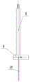
Fig. 1 is a schematic structural diagram of the present invention;
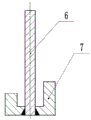
FIG. 2 is a cross-sectional view of the center positioning post of the present invention;
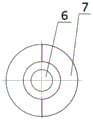
fig. 3 is a top view of the center positioning post of the present invention;
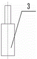
FIG. 4 is a front view of the positioning post of the support plate of the present invention;
FIG. 5 is a front view of the fixing device of the present invention;
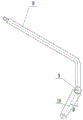
FIG. 6 is a front view of the left handlebar;
FIG. 7 is a side view of the left handlebar;
in the figure: 1. a base plate; 2. a central positioning column; 3. a support plate positioning column; 4. a fixing plate; 5. a side plate; 6. a column; 7. a base; 8. a handle; 9. a long shaft sleeve; 10. a connecting rod support plate.
Detailed Description
The technical solution in the embodiments of the present invention will now be clearly and completely described with reference to the accompanying drawings, which are simplified schematic drawings and only schematically illustrate the basic structure of the present invention.
In FIG. 1, a central positioning column 2 is fixed at a proper position of a bottom plate 1 to position a center, the central positioning column 2 fixes the position and the angle of a supporting plate positioning column 3, and then the position of a fixing device is positioned, the fixing device is positioned right above the central positioning column 2, and the distance between the fixing device and the central positioning column 2 is smaller than the length of the vertical side of a handle 8; the support plate positioning column 3 is positioned on the lower side of the central positioning column 2, an included angle alpha is formed between a connecting line of the support plate positioning column 3 and the center of the central positioning column 2 and the vertical direction, the included angle alpha is matched with the included angle beta between the connecting rod support plate 10 and the vertical direction, and the distance between the support plate positioning column 3 and the central positioning column 2 is matched with the length of the connecting rod support plate 10; the fixing device comprises a fixing plate 4, the width of the fixing plate 4 is matched with the outer diameter of a handle 8, the upper end of the fixing plate 4 is flush with the upper end of a base 7 facing one side of the fixing device, two sides of the fixing plate 4 are respectively connected with a side plate 5, and the upper end of the side plate 5 protrudes upwards out of the upper surface of the fixing plate 4; sleeving a long shaft sleeve 9 on an upright post 6 on a central positioning post 2 for fixing, sleeving one end with a hole of a connecting rod supporting plate 10 on a supporting plate positioning post, placing the other end on a semicircular table II at the higher end of a base 7 for attaching and fixing with the upright post 6, fixedly clamping the middle part of the vertical side of a handle 8 on a fixing plate 4 between two side plates 5, placing the end part to be welded on a semicircular table I at the lower end of the base 7, and contacting the end part to be welded of the handle 8 with the upright post 6; and finally, prewelding the contact surface of the handle 8 and the upright post 6, and prewelding the binding surface of the connecting rod support plate 10 and the upright post 6.
In fig. 2, the central positioning column 2 is composed of an upright column 6 and a base 7, the base 7 is sleeved at the bottom of the upright column 6, the upright column 6 is cylindrical, the diameter of the upright column 6 is matched with the inner diameter of a long shaft sleeve 9, after the long shaft sleeve 9 is sleeved on the upright column 6, the upright column 6 is still higher than the long shaft sleeve 9, the outer contour of the base 7 is circular, a step hole is formed in the middle of the base 7, the large hole of the step hole is matched with the outer diameter of the long shaft sleeve 9, the small hole of the step hole is matched with the diameter of the upright column 6, two semicircular tables with different heights are arranged on the upper portion of the base 7, the height of the first semicircular table on one side of the base 7, which faces towards a fixing device, is lower than that of the second semicircular table on the.
Fig. 3 is a top view of fig. 2.
In fig. 4, the outer surface of the support plate positioning column 3 is a stepped cylindrical surface, the stepped cylindrical surface includes an upper cylindrical surface and a lower cylindrical surface, the diameter of the upper cylindrical surface is smaller than that of the lower cylindrical surface, the upper end of the lower cylindrical surface is flush with the upper end of the base 7 facing one side of the support plate positioning column 3, the outer diameter of the upper cylindrical surface is smaller than the inner diameter of the hole of the connecting rod support plate 10, the height of the hole is larger than the thickness of the connecting rod support plate 10.
FIG. 5 is a front view of the fixing device; fixing device includes fixed plate 4, and 4 width of fixed plate and 8 external diameter phase-matchs of handle, and 4 upper ends of fixed plate and 7 upper ends parallel and level of base towards fixing device one side, the both sides of fixed plate 4 are connected with a curb plate 5 respectively, and 5 upper ends of curb plate upwards bulge fixed plate 4 upper surfaces.
In fig. 6, the left control handle is composed of a handle 8, a long shaft sleeve 9 and a connecting rod support plate 10, the handle 8 and the connecting rod support plate 10 are respectively welded on two sides of the long shaft sleeve, and a vertical rod at the connecting end of the handle 8 and the long shaft sleeve 9 is the vertical side of the handle 8.
Fig. 7 is a side view of fig. 6.
Claims (9)
1. The utility model provides a left control handle prewelding device of trucd mixer, its characterized in that: a central positioning column (2) for fixing a long shaft sleeve (9) of a left control handle to be welded, a fixing device for fixing a handle (8) of the left control handle to be welded and a support plate positioning column (3) for fixing a connecting rod support plate (10) of the left control handle to be welded are arranged on the bottom plate (1);
the fixing device is positioned right above the central positioning column (2), and the distance between the fixing device and the central positioning column (2) is smaller than the length of the vertical side of the handle (8); the support plate positioning column (3) is positioned at the lower left side of the central positioning column (2), an included angle alpha is formed between a connecting line of the support plate positioning column (3) and the center of the central positioning column (2) and the vertical direction, the included angle alpha is matched with the included angle beta between the connecting rod support plate (10) and the vertical direction, and the distance between the support plate positioning column (3) and the central positioning column (2) is matched with the length of the connecting rod support plate (10); the central positioning column (2) comprises a vertical column (6) and a base (7), and the base (7) is sleeved at the bottom of the vertical column (6).
2. The left handlebar pre-welding device of the mixer truck as set forth in claim 1, wherein: the diameter of the upright post (6) is matched with the inner diameter of the long shaft sleeve (9).
3. The left handlebar pre-welding device of the mixer truck as set forth in claim 1, wherein: the middle part of the base (7) is provided with a step hole, the large hole of the step hole is matched with the outer diameter of the long shaft sleeve (9), and the small hole of the step hole is matched with the diameter of the upright post (6).
4. The left handlebar pre-welding device of the mixer truck as set forth in claim 1, wherein: the upper part of the base (7) is provided with two semi-circular tables with different heights, and the height of the first semi-circular table on one side of the base (7) facing the fixing device is lower than that of the second semi-circular table on the other side of the base (7).
5. The left handlebar pre-welding device of the mixer truck as set forth in claim 4, wherein: the height of the first half round platform is level with the position to be welded of the handle (8), and the height of the second half round platform is level with the position to be welded of the connecting rod support plate (10).
6. The left handlebar pre-welding device of the mixer truck as set forth in claim 1, wherein: the fixing device comprises a fixing plate (4), the width of the fixing plate (4) is matched with the outer diameter of the handle (8), and the upper end of the fixing plate (4) is flush with the upper end of the base (7) facing one side of the fixing device.
7. The left handlebar pre-welding device of the mixer truck as set forth in claim 6, wherein: two sides of the fixed plate (4) are respectively connected with a side plate (5), and the upper end of the side plate (5) protrudes upwards out of the upper surface of the fixed plate (4).
8. The left handlebar pre-welding device of the mixer truck as set forth in claim 1, wherein: the outer surface of the support plate positioning column (3) is a stepped cylindrical surface, the stepped cylindrical surface comprises an upper cylindrical surface and a lower cylindrical surface, the diameter of the upper cylindrical surface is smaller than that of the lower cylindrical surface, and the upper end of the lower cylindrical surface is flush with the upper end of the base (7) on one side facing the support plate positioning column (3).
9. The left handlebar pre-welding device of the mixer truck as set forth in claim 8, wherein: the diameter of the upper cylindrical surface is smaller than the aperture of the through hole on the connecting rod support plate (10), and the height of the upper cylindrical surface is larger than the thickness of the connecting rod support plate (10).
Priority Applications (1)
| Application Number | Priority Date | Filing Date | Title |
|---|---|---|---|
| CN202021368775.1U CN212265026U (en) | 2020-07-14 | 2020-07-14 | Left control handle pre-welding device of mixer truck |
Applications Claiming Priority (1)
| Application Number | Priority Date | Filing Date | Title |
|---|---|---|---|
| CN202021368775.1U CN212265026U (en) | 2020-07-14 | 2020-07-14 | Left control handle pre-welding device of mixer truck |
Publications (1)
| Publication Number | Publication Date |
|---|---|
| CN212265026U true CN212265026U (en) | 2021-01-01 |
Family
ID=73898490
Family Applications (1)
| Application Number | Title | Priority Date | Filing Date |
|---|---|---|---|
| CN202021368775.1U Expired - Fee Related CN212265026U (en) | 2020-07-14 | 2020-07-14 | Left control handle pre-welding device of mixer truck |
Country Status (1)
| Country | Link |
|---|---|
| CN (1) | CN212265026U (en) |
-
2020
- 2020-07-14 CN CN202021368775.1U patent/CN212265026U/en not_active Expired - Fee Related
Similar Documents
| Publication | Publication Date | Title |
|---|---|---|
| CN202192389U (en) | Universal all-position welding test piece supporting positioning rack for plates and pipes | |
| CN106271326B (en) | A kind of robot welding fixture of decontamination apparatus | |
| CN213380103U (en) | Welding positioning device for seamless steel pipe and flange | |
| CN201792157U (en) | Universal motorcycle frame welding fixture | |
| CN209830745U (en) | Flowmeter welding frock | |
| CN202763342U (en) | Motorcycle head combination welding positioning device | |
| CN113927229A (en) | Left control handle pre-welding device of mixer truck | |
| CN202622258U (en) | Grouping fixture for rear bracket of concrete mixer | |
| CN109531011B (en) | Welding fixture for automobile body framework | |
| CN221185269U (en) | Battery tray fixed-position welding frock | |
| CN211162636U (en) | A welding tool for a thrust rod beam assembly of a tourist vehicle | |
| CN205309664U (en) | Fire control cantilever crane axle sleeve rivet welding frock | |
| CN212169453U (en) | Welding fixture for rib plate of transformer | |
| CN222660588U (en) | Welding tool for automobile rear longitudinal beam reinforcing plate assembly | |
| CN203679590U (en) | Welding location clamping device | |
| CN218904102U (en) | Supporting shallow welding frock | |
| CN109060366B (en) | Tool and method for detecting auxiliary frame of bogie | |
| CN222575613U (en) | A fast and accurate positioning excavator frame | |
| CN219151963U (en) | Bracket welding tool with low cost and convenience and quickness | |
| CN220445478U (en) | Steel structure stand auxiliary standing welding device | |
| CN219310342U (en) | Clamp for laser welding of guide piece and upper cover of double-core battery | |
| CN223519013U (en) | Welding tool for automobile steering column | |
| CN224196215U (en) | A frame positioning welding fixture for a battery clamping platform | |
| CN215280632U (en) | A table leg welding fixture and table leg | |
| CN222660560U (en) | A welding tool for the seat base of an excavator |
Legal Events
| Date | Code | Title | Description |
|---|---|---|---|
| GR01 | Patent grant | ||
| GR01 | Patent grant | ||
| CF01 | Termination of patent right due to non-payment of annual fee |
Granted publication date: 20210101 |
|
| CF01 | Termination of patent right due to non-payment of annual fee |