CN212258874U - Solar energy charging device - Google Patents
Solar energy charging device Download PDFInfo
- Publication number
- CN212258874U CN212258874U CN202021069030.5U CN202021069030U CN212258874U CN 212258874 U CN212258874 U CN 212258874U CN 202021069030 U CN202021069030 U CN 202021069030U CN 212258874 U CN212258874 U CN 212258874U
- Authority
- CN
- China
- Prior art keywords
- battery plate
- charging device
- photoresistor
- support rod
- controller
- Prior art date
- Legal status (The legal status is an assumption and is not a legal conclusion. Google has not performed a legal analysis and makes no representation as to the accuracy of the status listed.)
- Expired - Fee Related
Links
Images


Classifications
-
- Y—GENERAL TAGGING OF NEW TECHNOLOGICAL DEVELOPMENTS; GENERAL TAGGING OF CROSS-SECTIONAL TECHNOLOGIES SPANNING OVER SEVERAL SECTIONS OF THE IPC; TECHNICAL SUBJECTS COVERED BY FORMER USPC CROSS-REFERENCE ART COLLECTIONS [XRACs] AND DIGESTS
- Y02—TECHNOLOGIES OR APPLICATIONS FOR MITIGATION OR ADAPTATION AGAINST CLIMATE CHANGE
- Y02E—REDUCTION OF GREENHOUSE GAS [GHG] EMISSIONS, RELATED TO ENERGY GENERATION, TRANSMISSION OR DISTRIBUTION
- Y02E10/00—Energy generation through renewable energy sources
- Y02E10/40—Solar thermal energy, e.g. solar towers
- Y02E10/47—Mountings or tracking
-
- Y—GENERAL TAGGING OF NEW TECHNOLOGICAL DEVELOPMENTS; GENERAL TAGGING OF CROSS-SECTIONAL TECHNOLOGIES SPANNING OVER SEVERAL SECTIONS OF THE IPC; TECHNICAL SUBJECTS COVERED BY FORMER USPC CROSS-REFERENCE ART COLLECTIONS [XRACs] AND DIGESTS
- Y02—TECHNOLOGIES OR APPLICATIONS FOR MITIGATION OR ADAPTATION AGAINST CLIMATE CHANGE
- Y02E—REDUCTION OF GREENHOUSE GAS [GHG] EMISSIONS, RELATED TO ENERGY GENERATION, TRANSMISSION OR DISTRIBUTION
- Y02E10/00—Energy generation through renewable energy sources
- Y02E10/50—Photovoltaic [PV] energy
Landscapes
- Photovoltaic Devices (AREA)
Abstract
本实用新型公开了一种太阳能充电装置,包括电池板,电池板活动连接有支撑机构,电池板内设置有光照传感器,电池板至少两个侧壁上对称设置有光敏电阻板,支撑机构上设置有驱动电池板转动的驱动机构,驱动机构分别与光敏电阻板、光照传感器连接。能大效率获得太阳能,减少太阳光转化成太阳能的损耗,提高太阳能板的使用价值;同时可以作为沙滩遮阳装置,为游客提供这样空间。

The utility model discloses a solar charging device, which comprises a battery plate, a support mechanism is movably connected to the battery plate, a light sensor is arranged in the battery plate, photoresistor plates are symmetrically arranged on at least two side walls of the battery plate, and a support mechanism is arranged on the support mechanism. There is a driving mechanism for driving the battery board to rotate, and the driving mechanism is respectively connected with the photosensitive resistance board and the light sensor. It can obtain solar energy with high efficiency, reduce the loss of converting sunlight into solar energy, and improve the use value of solar panels; at the same time, it can be used as a beach shading device to provide such space for tourists.
Description
技术领域technical field
本实用新型属于新能源技术领域,涉及一种太阳能充电装置。The utility model belongs to the technical field of new energy, and relates to a solar charging device.
背景技术Background technique
沙滩的自然环境,减少了附近高层建筑对太阳光的遮挡,能更好收集太阳光能源,此外,沙滩上游客受太阳照射多,因此在沙滩户外环境中设置太阳能充电板,可在遮阳同时最大限度采集太阳光,转化为热量。目前,太阳能运用广泛,优点显著,其具有环保型,可持续性,可靠性等,但由于一天内太阳照射角度产生变化,产能时间有限,因此如何提高太阳能转化效率,高效使用太阳能成为太阳能充电装置的改进方向。The natural environment of the beach reduces the shading of the sunlight by nearby high-rise buildings, and can better collect sunlight energy. In addition, tourists on the beach are exposed to the sun a lot. Therefore, solar charging panels are installed in the outdoor environment of the beach, which can maximize the shading and at the same time. Limit the collection of sunlight and convert it into heat. At present, solar energy is widely used and has significant advantages. It is environmentally friendly, sustainable, reliable, etc. However, due to the change of the sun irradiation angle within a day, the production time is limited, so how to improve the conversion efficiency of solar energy and use solar energy efficiently to become a solar charging device direction of improvement.
实用新型内容Utility model content
本实用新型的目的是提供一种太阳能充电装置,解决了现有技术中存在的太阳能转化率低的问题。The purpose of the utility model is to provide a solar charging device, which solves the problem of low solar energy conversion rate existing in the prior art.
本实用新型所采用的技术方案是,一种太阳能充电装置,包括电池板,电池板活动连接有支撑机构,电池板内设置有光照传感器,电池板至少两个侧壁上对称设置有光敏电阻板,支撑机构上设置有驱动电池板转动的驱动机构,驱动机构分别与光敏电阻板、光照传感器连接。The technical scheme adopted by the utility model is that a solar charging device comprises a battery plate, the battery plate is movably connected with a support mechanism, a light sensor is arranged in the battery plate, and photoresistor plates are symmetrically arranged on at least two side walls of the battery plate The support mechanism is provided with a driving mechanism for driving the battery plate to rotate, and the driving mechanism is respectively connected with the photoresistor plate and the light sensor.
本实用新型的特点还在于:The utility model is characterized in that:
支撑机构包括主支架,主支架通过驱动机构活动连接有支杆,支杆与电池板连接。The support mechanism includes a main bracket, the main bracket is movably connected with a support rod through the driving mechanism, and the support rod is connected with the battery plate.
驱动机构包括控制器,控制器与光照传感器、光敏电阻板连接;控制器还分别电性连接有第一步进电机、第二步进电机,控制器、第一步进电机位于主支架内;第一步进电机输出轴上套接有旋转盘,旋转盘上固定有铰座,第二步进电机输出轴穿过铰座,第二步进电机输出轴连接有齿轮,且齿轮位于铰座内;支杆上连接有连接件,连接件内开设有与齿轮相啮合的通孔,齿轮位于通孔内。The driving mechanism includes a controller, and the controller is connected with the light sensor and the photoresistor board; the controller is also electrically connected with a first stepping motor and a second stepping motor, and the controller and the first stepping motor are located in the main bracket; A rotating disc is sleeved on the output shaft of the first stepping motor, a hinge seat is fixed on the rotating disc, the output shaft of the second stepping motor passes through the hinge base, and the output shaft of the second stepping motor is connected with a gear, and the gear is located in the hinge base The support rod is connected with a connecting piece, a through hole meshing with the gear is opened in the connecting piece, and the gear is located in the through hole.
支杆靠近电池板一端设置有肋板,肋板与电池板接触。One end of the support rod close to the battery plate is provided with a rib, and the rib is in contact with the battery plate.
支杆另一端连接有重锤。The other end of the support rod is connected with a heavy hammer.
本实用新型的有益效果是:The beneficial effects of the present utility model are:
本实用新型一种太阳能充电装置,根据光敏电阻板接收光照强度的差异,通过驱动机构控制电池板的转动,使得太阳光直射方向始终与太阳能板垂直,最大效率获得太阳能,减少太阳光转化成太阳能的损耗,提高太阳能板的使用价值;同时可以作为沙滩遮阳装置,为游客提供这样空间。The utility model relates to a solar charging device. According to the difference of the light intensity received by the photoresistor plate, the rotation of the battery plate is controlled by the driving mechanism, so that the direct sunlight direction is always perpendicular to the solar energy plate, the solar energy is obtained with the maximum efficiency, and the conversion of the sunlight into the solar energy is reduced. At the same time, it can be used as a beach sunshade device to provide such space for tourists.
附图说明Description of drawings
图1是本实用新型一种太阳能充电装置的结构示意图;1 is a schematic structural diagram of a solar charging device of the present invention;
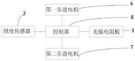
图2是本实用新型一种太阳能充电装置中控制器的结构示意图;2 is a schematic structural diagram of a controller in a solar charging device of the present invention;
图3是本实用新型一种太阳能充电装置中驱动机构的结构示意图。3 is a schematic structural diagram of a driving mechanism in a solar charging device of the present invention.
图中,1.电池板,2.光照传感器,3.光敏电阻板,4.主支架,5.支杆,6.第一步进电机,7.第二步进电机,8.控制器,9.旋转盘,10.铰座,11.齿轮,12.连接件,13.通孔,14.肋板,15.重锤,16.底座。In the figure, 1. Battery board, 2. Light sensor, 3. Photoresistor board, 4. Main bracket, 5. Support rod, 6. First stepper motor, 7. Second stepper motor, 8. Controller, 9. Rotating plate, 10. hinge seat, 11. gear, 12. connecting piece, 13. through hole, 14. rib, 15. weight, 16. base.
具体实施方式Detailed ways
下面结合附图和具体实施方式对本实用新型进行详细说明。The present utility model will be described in detail below with reference to the accompanying drawings and specific embodiments.
一种太阳能充电装置,如图1所示,包括电池板1,电池板1活动连接有支撑机构,电池板1内设置有光照传感器2,电池板1至少两个侧壁上对称设置有光敏电阻板3,支撑机构上设置有驱动电池板1转动的驱动机构,驱动机构分别与光敏电阻板3、光照传感器2连接。光照传感器2采集太阳的照射强度,当达到预设值时,光照传感器2发送信号至控制器8,控制器8开启。A solar charging device, as shown in FIG. 1 , includes a battery plate 1, a support mechanism is movably connected to the battery plate 1, a
优选的,光敏电阻板3为光敏电阻(环氧树脂封装)-导线型(DIP),规格为光敏电阻-¢3mm系列;光照传感器的型号为HA2003。Preferably, the
本实施例中光敏电阻板3的数量为四个,电池板1的四个侧壁分别设置一个,在四个方向上接收光照,根据光敏电阻板3接受光照强度的差异,接收光强多的光敏电阻阻值减小,进而通过驱动机构控制电池板1转动,直至四个光敏电阻板3上的光照强度相同。In this embodiment, the number of
支撑机构包括主支架4,主支架4通过驱动机构活动连接有支杆5,支杆5与电池板1连接。主支架4的内部中空,底部连接有底座16。The support mechanism includes a
如图2所示,驱动机构包括控制器8,本实施例中控制器8为单片机,优选的,控制器8为P1C886单片机。控制器8与光照传感器2、光敏电阻板3连接;控制器8还分别电性连接有第一步进电机6、第二步进电机7,控制器8、第一步进电机6位于主支架4内,第一步进电机6固定在主支架一端;如图3所示,第一步进电机6输出轴上套接有旋转盘9,旋转盘9上固定有铰座10,第二步进电机7输出轴穿过铰座10,第二步进电机7输出轴连接有齿轮11,且齿轮11位于铰座10内;支杆5上连接有连接件12,连接件12位于铰座10内,连接件12内开设有与齿轮11相啮合的通孔13,齿轮11位于通孔13内,工作时,齿轮11转动,带动连接件12转动。旋转盘9随第一步进电机6转动,通过铰座10、连接件12带动支杆5转动,进而实现电池板1的左右转动;齿轮11随第二步进电机7输出轴转动,通过连接件12带动支杆5转动,进而实现电池板1的上下转动。As shown in FIG. 2 , the driving mechanism includes a
支杆5靠近电池板1一端设置有肋板14,肋板14与电池板1接触。支杆5另一端连接有重锤15。肋板14、重锤15均能增加电池板1自身稳定性,减少运动惯性,可减少摆动时的摇晃。A
本实用新型一种太阳能充电装置的工作工程如下:The working engineering of a solar charging device of the utility model is as follows:
将太阳能充电装置放在沙滩环境中,光照传感器2采集太阳的照射强度,当达到预设值时,光照传感器2发送信号至控制器8,控制器8开启。光敏电阻板3根据太阳光照方向的变化,每个方向的光敏电阻板3接受光照强度的产生差异,接收光强多的光敏电阻阻值减小,将脉冲信号通过控制器8分别输出至第一步进电机6、第二步进电机7,第一步进电机6驱动旋转盘9转动,进而通过铰座10、连接件12带动支杆5转动,实现电池板1的左右转动,第二步进电机7通过齿轮11带动连接件12转动,进而带动支杆5转动,实现电池板1的上下转动;直至电池板1转动到光照强度相同位置,四个光敏电阻板3阻值相同,电池板1停止转动,此时太阳光直射电池板1。The solar charging device is placed in the beach environment, and the
通过以上方式,本实用新型一种太阳能充电装置,根据光敏电阻板接收光照强度的差异,通过驱动机构控制电池板的转动,使得太阳光直射方向始终与太阳能板垂直,最大效率获得太阳能,减少太阳光转化成太阳能的损耗,提高太阳能板的使用价值;同时可以作为沙滩遮阳装置,为游客提供这样空间。Through the above method, a solar charging device of the present invention controls the rotation of the battery plate through the driving mechanism according to the difference in the light intensity received by the photoresistor plate, so that the direct sunlight direction is always perpendicular to the solar plate, and the maximum efficiency is obtained. The loss of light converted into solar energy increases the use value of solar panels; at the same time, it can be used as a beach shading device to provide such a space for tourists.
Claims (5)
Priority Applications (1)
| Application Number | Priority Date | Filing Date | Title |
|---|---|---|---|
| CN202021069030.5U CN212258874U (en) | 2020-06-11 | 2020-06-11 | Solar energy charging device |
Applications Claiming Priority (1)
| Application Number | Priority Date | Filing Date | Title |
|---|---|---|---|
| CN202021069030.5U CN212258874U (en) | 2020-06-11 | 2020-06-11 | Solar energy charging device |
Publications (1)
| Publication Number | Publication Date |
|---|---|
| CN212258874U true CN212258874U (en) | 2020-12-29 |
Family
ID=73988306
Family Applications (1)
| Application Number | Title | Priority Date | Filing Date |
|---|---|---|---|
| CN202021069030.5U Expired - Fee Related CN212258874U (en) | 2020-06-11 | 2020-06-11 | Solar energy charging device |
Country Status (1)
| Country | Link |
|---|---|
| CN (1) | CN212258874U (en) |
-
2020
- 2020-06-11 CN CN202021069030.5U patent/CN212258874U/en not_active Expired - Fee Related
Similar Documents
| Publication | Publication Date | Title |
|---|---|---|
| CN217789613U (en) | A solar photovoltaic panel angle adjustment device and photovoltaic power generation device | |
| CN207080154U (en) | Intelligent tracing type solar shutter | |
| CN207947749U (en) | A kind of energy saving building photovoltaic curtain wall with day rotation | |
| CN221784916U (en) | Solar irrigation controller | |
| CN216490287U (en) | A community new energy comprehensive utilization device | |
| CN218124624U (en) | Photovoltaic solar panel convenient to adjust | |
| CN101093114A (en) | Improved type sunlight automatic track follower | |
| CN206251030U (en) | A kind of wind-light complementing power generation device | |
| CN214069862U (en) | Solar energy environmental protection and energy saving building system | |
| CN212063916U (en) | Automatic light-following type power generation device and control system thereof | |
| CN113251675B (en) | Solar heat collecting device | |
| CN212226909U (en) | Solar street lamp with movable support | |
| CN212163221U (en) | Reflection type solar cell panel device | |
| CN212204360U (en) | A solar LED street light with good wind resistance | |
| CN210395769U (en) | Energy-conserving building photovoltaic curtain that light energy utilization rate is high | |
| CN211321265U (en) | A concentrating solar panel | |
| CN212543713U (en) | An all-round solar power supply system | |
| CN207603533U (en) | A kind of device for photovoltaic generation | |
| CN223402423U (en) | Environment-friendly energy-saving building structure | |
| CN218771979U (en) | Concentrating photovoltaic power generation device | |
| CN201237136Y (en) | Wind and solar energy mutual-complementing road lamp | |
| CN218482816U (en) | Solar photovoltaic power generation and energy storage integrated device | |
| CN219780044U (en) | Photovoltaic bracket convenient to install | |
| CN211127653U (en) | Comprehensive device for improving utilization rate of wind energy and solar energy based on angle change | |
| CN215734157U (en) | Multi-energy complementary energy-saving control equipment |
Legal Events
| Date | Code | Title | Description |
|---|---|---|---|
| GR01 | Patent grant | ||
| GR01 | Patent grant | ||
| CF01 | Termination of patent right due to non-payment of annual fee |
Granted publication date: 20201229 Termination date: 20210611 |
|
| CF01 | Termination of patent right due to non-payment of annual fee |