CN212258765U - Converter cabinet body and converter parallel operation system - Google Patents

Converter cabinet body and converter parallel operation system Download PDF

Info

Publication number
CN212258765U
CN212258765U CN202021207127.8U CN202021207127U CN212258765U CN 212258765 U CN212258765 U CN 212258765U CN 202021207127 U CN202021207127 U CN 202021207127U CN 212258765 U CN212258765 U CN 212258765U
Authority
CN
China
Prior art keywords
cavity
frequency converter
wiring
air duct
inverter
Prior art date
Legal status (The legal status is an assumption and is not a legal conclusion. Google has not performed a legal analysis and makes no representation as to the accuracy of the status listed.)
Active
Application number
CN202021207127.8U
Other languages
Chinese (zh)
Inventor
刘晶晶
Current Assignee (The listed assignees may be inaccurate. Google has not performed a legal analysis and makes no representation or warranty as to the accuracy of the list.)
Beijing Huichuan Technology Co ltd
Original Assignee
Suzhou Inovance Technology Co Ltd
Priority date (The priority date is an assumption and is not a legal conclusion. Google has not performed a legal analysis and makes no representation as to the accuracy of the date listed.)
Filing date
Publication date
Application filed by Suzhou Inovance Technology Co Ltd filed Critical Suzhou Inovance Technology Co Ltd
Priority to CN202021207127.8U priority Critical patent/CN212258765U/en
Application granted granted Critical
Publication of CN212258765U publication Critical patent/CN212258765U/en
Active legal-status Critical Current
Anticipated expiration legal-status Critical

Links

Images

Landscapes

  • Inverter Devices (AREA)

Abstract

The utility model discloses a converter cabinet body and converter parallel operation system, wherein, the converter cabinet body includes the casing, first baffle and second baffle are installed in the casing, and separate the inner chamber of casing for first installation cavity, second installation cavity and wiring chamber, first installation cavity is used for installing first converter, the second installation cavity is used for installing the second converter, the wiring intracavity is equipped with the wiring installation position that supplies the terminal block to install, the terminal block is used for being connected with first converter and second converter electricity. The utility model discloses the converter cabinet body can reduce the size of the whole converter cabinet body, improves the space utilization of the converter cabinet body, reduces the doubling cost, reduces the place area occupied.

Description

变频器柜体及变频器并机系统Inverter cabinet and inverter parallel system

技术领域technical field

本实用新型涉及变频器技术领域,特别涉及一种变频器柜体及变频器并机系统。The utility model relates to the technical field of frequency converters, in particular to a frequency converter cabinet and a frequency converter parallel system.

背景技术Background technique

在实际应用中,为了增大变频器的输出功率,需要使用变频器并机技术,以满足不同应用场合的功率需求。在现有技术中,变频器并机时通常采用一字排开的方式设置于单独的柜体内,柜体的进线、出线、变频、制动等部分单独成柜。采用这种方式,柜体的整体尺寸会比较大,应用时需要较大的场地。在增大产品成本的同时,还会造成空间资源的浪费。In practical applications, in order to increase the output power of the inverter, it is necessary to use the inverter parallel technology to meet the power requirements of different applications. In the prior art, the frequency converters are usually arranged in a line in a separate cabinet when they are paralleled, and the incoming wires, outgoing wires, frequency conversion, braking and other parts of the cabinet are formed into separate cabinets. In this way, the overall size of the cabinet will be relatively large, and a large space is required for application. While increasing the product cost, it will also cause a waste of space resources.

上述内容仅用于辅助理解实用新型的技术方案,并不代表承认上述内容是现有技术。The above content is only used to assist the understanding of the technical solution of the utility model, and does not mean that the above content is the prior art.

实用新型内容Utility model content

本实用新型的主要目的是提出一种变频器柜体,旨在解决变频器并机时柜体尺寸大的技术问题。The main purpose of the utility model is to propose a frequency converter cabinet, which aims to solve the technical problem of the large size of the cabinet when the frequency converters are paralleled.

为实现上述目的,本实用新型提出的变频器柜体包括壳体、第一隔板及第二隔板,所述第一隔板及所述第二隔板安装于所述壳体内,且将所述壳体的内腔分隔为第一安装腔、第二安装腔及接线腔,所述第一安装腔用于安装第一变频器,所述第二安装腔用于安装第二变频器,所述接线腔内设有供接线部件安装的接线安装位,所述接线部件用于与所述第一变频器及所述第二变频器电连接。In order to achieve the above purpose, the inverter cabinet proposed by the present invention includes a housing, a first partition and a second partition. The first partition and the second partition are installed in the housing, and the The inner cavity of the housing is divided into a first installation cavity, a second installation cavity and a wiring cavity, the first installation cavity is used to install the first inverter, and the second installation cavity is used to install the second inverter, The wiring cavity is provided with a wiring installation position for installing wiring components, and the wiring components are used for electrical connection with the first frequency converter and the second frequency converter.

在一实施例中,所述第一安装腔、所述接线腔及所述第二安装腔并排设置,所述接线腔位于所述第一安装腔及所述第二安装腔之间。In one embodiment, the first installation cavity, the wiring cavity and the second installation cavity are arranged side by side, and the wiring cavity is located between the first installation cavity and the second installation cavity.

在一实施例中,所述第一隔板及所述第二隔板沿所述壳体的高度方向延伸,所述第一安装腔、所述接线腔及所述第二安装腔沿所述壳体的长度方向依次排布。In one embodiment, the first partition plate and the second partition plate extend along the height direction of the housing, and the first installation cavity, the wiring cavity and the second installation cavity are along the The length directions of the casings are arranged in sequence.

在一实施例中,所述接线腔内还限定出独立的第一散热风道,所述第一散热风道用于安装制动模块。In an embodiment, an independent first heat dissipation air duct is further defined in the wiring cavity, and the first heat dissipation air duct is used for installing the brake module.

在一实施例中,所述接线腔内还限定出与所述第一散热风道相互独立的第二散热风道,所述第二散热风道用于安装输出电抗器。In one embodiment, the wiring cavity further defines a second heat dissipation air duct independent of the first heat dissipation air duct, and the second heat dissipation air duct is used for installing the output reactor.

在一实施例中,所述壳体包括框体、安装于所述框体顶部的上面板、底部的下面板、前侧的前门板和后侧的背板,所述变频器柜体还包括与所述上面板并行的第一挡板及与所述背板并行的制动模块安装板,所述制动模块安装板连接于所述框体,且用于安装所述制动模块,所述制动模块安装板自所述第一挡板延伸至所述上面板,所述上面板、所述第一挡板、所述第一隔板、所述第二隔板、所述制动模块安装板与所述前门板围合形成所述第一散热风道,所述上面板开设有与所述第一散热风道连通的出风口,所述前门板开设有与所述第一散热风道连通的进风口。In one embodiment, the casing includes a frame body, an upper panel mounted on the top of the frame body, a lower panel at the bottom, a front door panel on the front side and a back panel on the rear side, and the inverter cabinet further includes: A first baffle plate parallel to the upper panel and a brake module installation plate parallel to the back plate, the brake module installation plate is connected to the frame and is used to install the brake module, so The brake module mounting plate extends from the first baffle to the upper panel, the upper panel, the first baffle, the first partition, the second partition, the brake The module mounting plate is enclosed with the front door panel to form the first cooling air duct, the upper panel is provided with an air outlet communicating with the first cooling air duct, and the front door panel is provided with an air outlet communicating with the first cooling air duct. Air duct connected to the air inlet.

在一实施例中,所述接线腔内还限定出与所述第一散热风道相互独立的第二散热风道,所述第二散热风道用于安装输出电抗器,所述变频器柜体还包括与所述背板并行的第二挡板,所述第二挡板由下向上延伸,所述第二挡板的上端与所述制动模块安装板的下端相连接,所述上面板、所述下面板、所述第一隔板、所述第二隔板、所述第二挡板、所述制动模块安装板与所述背板围合形成所述第二散热风道。In one embodiment, the wiring cavity further defines a second heat dissipation air duct independent of the first heat dissipation air duct, the second heat dissipation air duct is used for installing an output reactor, and the inverter cabinet is The body also includes a second baffle parallel to the back plate, the second baffle extends from bottom to top, the upper end of the second baffle is connected with the lower end of the brake module mounting plate, the upper The panel, the lower panel, the first partition plate, the second partition plate, the second baffle plate, the brake module mounting plate and the back plate are enclosed to form the second cooling air duct .

在一实施例中,所述制动模块安装板可拆卸地连接于所述框体,所述变频器柜体还包括与所述上面板并行的风机安装板,所述风机安装板与所述上面板之间形成所述散热风机安装位,所述风机安装板可前后抽拉地安装于框体,且抽出方向朝前设置,所述风机安装板用于供散热风机安装,所述散热风机用于驱动所述第二散热风道内的气流由所述出风口排出。In one embodiment, the brake module mounting plate is detachably connected to the frame body, the inverter cabinet further includes a fan mounting plate parallel to the upper panel, the fan mounting plate is connected to the The installation position of the cooling fan is formed between the upper panels. The fan mounting plate can be installed on the frame body in a front and rear manner, and the drawing direction is set forward. The fan mounting plate is used for the installation of the cooling fan. The airflow used to drive the second cooling air duct is discharged from the air outlet.

在一实施例中,所述壳体包括框体、安装于所述框体前侧的前门板和后侧的背板,所述前门板包括第一子门及第二子门,所述第一子门用以打开或关闭所述第一安装腔及所述接线腔,所述第二子门用以打开或关闭所述第二安装腔,所述第一子门上设有用于对第一变频器及第二变频器进行输入操作的控制键盘和/或用于控制第一变频器及第二变频器开关的输入断路器。In one embodiment, the housing includes a frame body, a front door panel mounted on the front side of the frame body and a back panel at the rear side, the front door panel includes a first sub-door and a second sub-door, the first sub-door A sub-door is used to open or close the first installation cavity and the wiring cavity, and the second sub-door is used to open or close the second installation cavity. A control keyboard for input operation of a frequency converter and a second frequency converter and/or an input circuit breaker for controlling the switches of the first frequency converter and the second frequency converter.

在一实施例中,所述接线安装位包括用于供输入母排安装的输入安装位和用于供输出母排安装的输出安装位,所述输入安装位及所述输入安装位安装于所述接线腔的下端,且呈前后、上下错位布置。In one embodiment, the wiring installation position includes an input installation position for input busbar installation and an output installation position for output busbar installation, and the input installation position and the input installation position are installed in the The lower end of the wiring cavity is arranged in a front-rear, up-and-down dislocation.

本实用新型还提出一种变频器并机系统,包括第一变频器、第二变频器及变频器柜体;The utility model also proposes a frequency converter parallel system, which includes a first frequency converter, a second frequency converter and a frequency converter cabinet;

所述变频器柜体包括壳体、第一隔板及第二隔板,所述第一隔板及所述第二隔板安装于所述壳体内,且将所述壳体的内腔分隔为第一安装腔、第二安装腔及接线腔,所述接线腔内设有供接线部件安装的接线安装位,所述接线部件用于与所述第一变频器及所述第二变频器电连接;The inverter cabinet includes a housing, a first partition and a second partition, and the first partition and the second partition are installed in the housing and separate the inner cavity of the housing It is a first installation cavity, a second installation cavity and a wiring cavity. The wiring cavity is provided with a wiring installation position for the installation of wiring components, and the wiring components are used for connecting with the first inverter and the second inverter. electrical connection;

所述第一变频器安装于第一安装腔,所述第二变频器安装于所述第二安装腔。The first frequency converter is installed in the first installation cavity, and the second frequency converter is installed in the second installation cavity.

本实用新型变频器柜体通过第一隔板及第二隔板将壳体的内腔分隔为第一安装腔、第二安装腔及接线腔,第一安装腔用于安装第一变频器,第二安装腔用于安装第二变频器,接线腔用于供与第一变频器及第二变频器电连接的接线部件安装。则变频器柜体能够同时供第一变频器及第二变频器安装,且使得与第一变频器及第二变频器电连接的接线部件均安装于独立的接线腔内,则相比于直接将单个的变频器柜体并排设置而言,使得每个变频器柜体的接线部件不用单独设置一个柜体,从而能够减小整个变频器柜体的尺寸,提高变频器柜体的空间利用率,降低并机成本,减少场地占用面积。同时,由于第一变频器及第二变频器的接线部件集成在同一个接线腔内,则使得整体的结构更加紧凑,且将两个变频器的接线部件集成模块化,更加便于工作人员对相关零部件的维修和更换,使得用户可以统一操作两个变频器,从而简化操作程序和步骤。The inverter cabinet of the utility model divides the inner cavity of the casing into a first installation cavity, a second installation cavity and a wiring cavity through the first partition plate and the second partition plate, and the first installation cavity is used for installing the first inverter. The second installation cavity is used for installing the second frequency converter, and the wiring cavity is used for installation of the wiring components electrically connected with the first frequency converter and the second frequency converter. Then the inverter cabinet can be installed for the first inverter and the second inverter at the same time, and the wiring components that are electrically connected to the first inverter and the second inverter are installed in the independent wiring cavity, compared with the direct In terms of arranging a single inverter cabinet side by side, the wiring components of each inverter cabinet do not need to be set up with a separate cabinet, thereby reducing the size of the entire inverter cabinet and improving the space utilization of the inverter cabinet. , reduce the cost of parallel machines, and reduce the area occupied by the site. At the same time, since the wiring components of the first frequency converter and the second frequency converter are integrated in the same wiring cavity, the overall structure is more compact, and the wiring components of the two frequency converters are integrated and modularized, which is more convenient for the staff to The repair and replacement of parts allows the user to operate the two inverters in a unified manner, thereby simplifying the operating procedures and procedures.

附图说明Description of drawings

为了更清楚地说明本实用新型实施例或现有技术中的技术方案,下面将对实施例或现有技术描述中所需要使用的附图作简单地介绍,显而易见地,下面描述中的附图仅仅是本实用新型的一些实施例,对于本领域普通技术人员来讲,在不付出创造性劳动的前提下,还可以根据这些附图示出的结构获得其他的附图。In order to more clearly illustrate the embodiments of the present utility model or the technical solutions in the prior art, the following briefly introduces the accompanying drawings that need to be used in the description of the embodiments or the prior art. Obviously, the accompanying drawings in the following description These are just some embodiments of the present invention, and for those of ordinary skill in the art, other drawings can also be obtained based on the structures shown in these drawings without any creative effort.

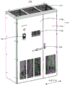
图1为本实用新型变频器柜体一实施例的结构示意图;1 is a schematic structural diagram of an embodiment of a frequency converter cabinet of the present invention;

图2为本实用新型变频器柜体另一实施例的结构示意图,其中,前门板被移除;FIG. 2 is a schematic structural diagram of another embodiment of the inverter cabinet of the present invention, wherein the front door panel is removed;

图3为本实用新型变频器柜体又一实施例的结构示意图,其中,背板被移除。FIG. 3 is a schematic structural diagram of another embodiment of the inverter cabinet of the present invention, wherein the backplane is removed.

附图标号说明:Description of reference numbers:

标号label 名称name 标号label 名称name 标号label 名称name 100100 变频器柜体Inverter cabinet 131131 第一安装腔first installation cavity 180180 控制键盘Control Keyboard 111111 框体framework 132132 第二安装腔Second installation cavity 190190 输入短路器input shunt 112112 上面板top panel 140140 接线腔wiring compartment 200200 第一变频器first inverter 112a112a 出风口air outlet 141141 接线安装位Wiring installation position 300300 第二变频器Second inverter 113113 下面板lower panel 142142 第一散热风道The first cooling air duct 400400 接线部件Wiring parts 114114 前门板front door panel 143143 第二散热风道Second cooling air duct 500500 制动模块brake module 114a114a 进风口Inlet 143a143a 散热风机安装位Cooling fan installation 600600 输出电抗器output reactor 114b114b 第一子门first child gate 150150 制动模块安装位Brake module mounting position 700700 散热风机Cooling fan 114c114c 第二子门second door 161161 第一挡板first baffle 800800 输入母排input busbar 121121 第一隔板first partition 162162 第二挡板second baffle 900900 输出母排output busbar 122122 第二隔板second partition 170170 风机安装板Fan mounting plate

本实用新型目的的实现、功能特点及优点将结合实施例,参照附图做进一步说明。The realization, functional characteristics and advantages of the purpose of the present utility model will be further described with reference to the accompanying drawings in conjunction with the embodiments.

具体实施方式Detailed ways

下面将结合本实用新型实施例中的附图,对本实用新型实施例中的技术方案进行清楚、完整地描述,显然,所描述的实施例仅仅是本实用新型的一部分实施例,而不是全部的实施例。基于本实用新型中的实施例,本领域普通技术人员在没有作出创造性劳动前提下所获得的所有其他实施例,都属于本实用新型保护的范围。The technical solutions in the embodiments of the present utility model will be clearly and completely described below with reference to the accompanying drawings in the embodiments of the present utility model. Obviously, the described embodiments are only a part of the embodiments of the present utility model, not all of them. Example. Based on the embodiments of the present invention, all other embodiments obtained by those of ordinary skill in the art without creative work fall within the protection scope of the present invention.

需要说明,若本实用新型实施例中有涉及方向性指示(诸如上、下、左、右、前、后……),则该方向性指示仅用于解释在某一特定姿态下各部件之间的相对位置关系、运动情况等,如果该特定姿态发生改变时,则该方向性指示也相应地随之改变。It should be noted that if there are directional indications (such as up, down, left, right, front, back...) in the embodiments of the present invention, the directional indications are only used to explain the relationship between the various components under a certain posture. If the specific posture changes, the directional indication also changes accordingly.

另外,若本实用新型实施例中有涉及“第一”、“第二”等的描述,则该“第一”、“第二”等的描述仅用于描述目的,而不能理解为指示或暗示其相对重要性或者隐含指明所指示的技术特征的数量。由此,限定有“第一”、“第二”的特征可以明示或者隐含地包括至少一个该特征。另外,全文中出现的“和/或”的含义为,包括三个并列的方案,以“A和/或B”为例,包括A方案,或B方案,或A和B同时满足的方案。另外,各个实施例之间的技术方案可以相互结合,但是必须是以本领域普通技术人员能够实现为基础,当技术方案的结合出现相互矛盾或无法实现时应当认为这种技术方案的结合不存在,也不在本实用新型要求的保护范围之内。In addition, if there are descriptions involving "first", "second", etc. in the embodiments of the present invention, the descriptions of "first", "second", etc. are only for the purpose of description, and should not be construed as instructions or Implicit their relative importance or implicitly indicate the number of technical features indicated. Thus, a feature delimited with "first", "second" may expressly or implicitly include at least one of that feature. In addition, the meaning of "and/or" in the whole text is to include three parallel schemes. Taking "A and/or B" as an example, it includes scheme A, scheme B, or scheme that A and B satisfy at the same time. In addition, the technical solutions between the various embodiments can be combined with each other, but must be based on the realization by those of ordinary skill in the art. When the combination of technical solutions is contradictory or cannot be realized, it should be considered that the combination of such technical solutions does not exist. , is not within the scope of protection required by the present utility model.

本实用新型提出一种变频器柜体,用于变频器并机系统。The utility model proposes a frequency converter cabinet, which is used in a frequency converter parallel system.

在本实用新型实施例中,如图1至图3所示,该变频器柜体100包括壳体、第一隔板121及第二隔板122,第一隔板121及第二隔板122安装于壳体内,且将壳体的内腔分隔为第一安装腔131、第二安装腔132及接线腔140,第一安装腔131用于安装第一变频器200,第二安装腔132用于安装第二变频器300,接线腔140内设有供接线部件400安装的接线安装位141,接线部件400用于与第一变频器200及第二变频器300电连接。In the embodiment of the present invention, as shown in FIG. 1 to FIG. 3 , the inverter cabinet 100 includes a casing, a first partition 121 and a second partition 122 , and the first partition 121 and the second partition 122 It is installed in the casing, and the inner cavity of the casing is divided into a first installation cavity 131, a second installation cavity 132 and a wiring cavity 140. The first installation cavity 131 is used to install the first inverter 200, and the second installation cavity 132 is used for When installing the second frequency converter 300 , the wiring cavity 140 is provided with a wiring installation position 141 for installing the wiring component 400 , and the wiring component 400 is used for electrical connection with the first frequency converter 200 and the second frequency converter 300 .

在本实施例中,壳体一般呈立方体或长方体状,壳体内限定出空腔。第一隔板121、第二隔板122与壳体可以一体成型设置,也可以分体成型,则第一隔板121、第二隔板122与壳体可以为可拆卸连接,如通过螺钉、卡扣、卡槽等方式连接。第一隔板121与第二隔板122可以并行设置,此时,第一隔板121与第二隔板122可以将壳体的内腔分隔为从左至右并排的三个腔,也可以分隔为从前至后并排的三个腔,或者从上至下并排的三个腔。第一隔板121与第二隔板122也可以呈交叉,如垂直设置。则第一隔板121与第二隔板122可以将壳体的内腔分隔一个上腔、两个并排的下腔,或者分隔为一个下腔、两个并排的上腔,还可以分隔为两个并排的前腔、一个后腔,或两个并排的左腔、一个右腔等,第一隔板121与第二隔板122将壳体的内腔分隔为三个腔的形式还有很多种,在此不做一一列举。可以理解的是,通常将两个尺寸相同的腔设置为第一安装腔131和第二安装腔132,且当三个腔呈并排设置时,将中间的腔设置为接线腔140,如此,便于第一变频器200和第二变频器300的安装及接线。In this embodiment, the casing is generally in the shape of a cube or a rectangular parallelepiped, and a cavity is defined in the casing. The first partition 121, the second partition 122 and the housing can be integrally formed or formed separately, and the first partition 121, the second partition 122 and the housing can be detachably connected, such as by screws, Snaps, card slots, etc. are connected. The first partition plate 121 and the second partition plate 122 can be arranged in parallel. At this time, the first partition plate 121 and the second partition plate 122 can divide the inner cavity of the housing into three cavities side by side from left to right. Divided into three chambers side by side from front to back, or three chambers side by side from top to bottom. The first partition plate 121 and the second partition plate 122 may also be intersected, such as vertically arranged. Then the first partition plate 121 and the second partition plate 122 can divide the inner cavity of the housing into an upper cavity, two side-by-side lower cavities, or into a lower cavity, two side-by-side upper cavities, or into two side-by-side upper cavities. There are two side-by-side front chambers, one rear chamber, or two side-by-side left chambers, one right chamber, etc. There are many forms in which the first partition 121 and the second partition 122 divide the inner cavity of the housing into three cavities. species, which are not listed here. It can be understood that two cavities with the same size are usually set as the first installation cavity 131 and the second installation cavity 132, and when the three cavities are arranged side by side, the middle cavity is set as the wiring cavity 140, so that it is convenient to Installation and wiring of the first inverter 200 and the second inverter 300 .

通常,变频器并机系统还包括电气器件及接线部件400,接线部件400包括分流母排、输出母排900、输入母排800和汇流母排;则分流母排、输出母排900、输入母排800和汇流母排均可以安装至接线腔140内。主回路原理为:输入电流由输入母排800经过电气器件,通过分流母排,从第一变频器200和第二变频器300的输入触头进入第一变频器200及第二变频器300。经过变频处理的电流由第一变频器200及第二变频器300的输出触头流向汇流母排,最后到达输出母排900。Usually, the inverter parallel system also includes electrical devices and wiring components 400. The wiring components 400 include a shunt busbar, an output busbar 900, an input busbar 800 and a busbar busbar; then the shunt busbar, the output busbar 900, the input busbar Both the row 800 and the bus bar can be installed into the wiring cavity 140 . The principle of the main circuit is as follows: the input current flows from the input busbar 800 through the electrical device, and enters the first inverter 200 and the second inverter 300 from the input contacts of the first inverter 200 and the second inverter 300 through the shunt busbar. The frequency-converted current flows from the output contacts of the first inverter 200 and the second inverter 300 to the busbar, and finally reaches the output busbar 900 .

本实用新型变频器柜体100通过第一隔板121及第二隔板122将壳体的内腔分隔为第一安装腔131、第二安装腔132及接线腔140,第一安装腔131用于安装第一变频器200,第二安装腔132用于安装第二变频器300,接线腔140用于供与第一变频器200及第二变频器300电连接的接线部件400安装。则变频器柜体100能够同时供第一变频器200及第二变频器300安装,且使得与第一变频器200及第二变频器300电连接的接线部件400均安装于独立的接线腔140内,则相比于直接将单个的变频器柜体100并排设置而言,使得每个变频器柜体100的接线部件400不用单独设置一个柜体,从而能够减小整个变频器柜体100的尺寸,提高变频器柜体100的空间利用率,降低并机成本,减少场地占用面积。同时,由于第一变频器200及第二变频器300的接线部件400集成在同一个接线腔140内,则使得整体的结构更加紧凑,且将两个变频器的接线部件400集成模块化,更加便于工作人员对相关零部件的维修和更换,使得用户可以统一操作两个变频器,从而简化操作程序和步骤。The inverter cabinet 100 of the present invention divides the inner cavity of the casing into a first installation cavity 131, a second installation cavity 132 and a wiring cavity 140 through the first partition plate 121 and the second partition plate 122. The first installation cavity 131 is used for For installing the first inverter 200 , the second installation cavity 132 is used for installing the second inverter 300 , and the wiring cavity 140 is used for installing the wiring component 400 electrically connected to the first inverter 200 and the second inverter 300 . Then the inverter cabinet 100 can be installed for the first inverter 200 and the second inverter 300 at the same time, and the wiring components 400 electrically connected with the first inverter 200 and the second inverter 300 are installed in the independent wiring cavity 140 compared to directly arranging the individual inverter cabinets 100 side by side, the wiring components 400 of each inverter cabinet 100 do not need to be provided with a separate cabinet, so that the total frequency of the inverter cabinet 100 can be reduced. size, improve the space utilization rate of the inverter cabinet 100, reduce the cost of parallel machines, and reduce the area occupied by the site. At the same time, since the wiring components 400 of the first inverter 200 and the second inverter 300 are integrated in the same wiring cavity 140, the overall structure is more compact, and the wiring components 400 of the two inverters are integrated and modularized, making it easier to It is convenient for the staff to maintain and replace the related parts, so that the user can operate the two inverters in a unified way, thereby simplifying the operation procedures and steps.

在一实施例中,请参照图2及图3,第一安装腔131、接线腔140及第二安装腔132并排设置,接线腔140位于第一安装腔131及第二安装腔132之间。通过使得第一安装腔131、接线腔140及第二安装腔132依次排列,则在安装第一变频器200及第二变频器300时,使得第一变频器200及第二变频器300位于接线腔140的两侧,使得第一变频器200与第二变频器300至接线腔140的距离更短,从而更加易于接线,且使得整体的接线线路更加简洁。In one embodiment, please refer to FIG. 2 and FIG. 3 , the first installation cavity 131 , the wiring cavity 140 and the second installation cavity 132 are arranged side by side, and the wiring cavity 140 is located between the first installation cavity 131 and the second installation cavity 132 . By arranging the first installation cavity 131 , the wiring cavity 140 and the second installation cavity 132 in sequence, when the first inverter 200 and the second inverter 300 are installed, the first inverter 200 and the second inverter 300 are located in the wiring The two sides of the cavity 140 make the distance from the first frequency converter 200 and the second frequency converter 300 to the wiring cavity 140 shorter, so that wiring is easier and the overall wiring circuit is more concise.

进一步地,如图2及图3所示,第一隔板121及第二隔板122沿壳体的高度方向延伸,第一安装腔131、接线腔140及第二安装腔132沿壳体的长度方向依次排布。如此,使得第一安装腔131、接线腔140及第二安装腔132从左至右并排设置,则使得整个变频器柜体100的深度可以保持不变,也即保持标准深度。且使得第一变频器200及第二变频器300为竖直安装至第一安装腔131及第二安装腔132内,则更加易于第一变频器200及第二变频器300的安装。具体可以使得第一变频器200及第二变频器300固定在壳体的框体111上。呈横向一字排开的三个腔体更加便于工作人员的接线操作,且使得整体的结构更加紧凑,能够有效减小变频器柜体100长度方向(行业内也常称为宽度方向)的尺寸。具体地,第一变频器200及第二变频器300可以采用同种规格,且使得第一变频器200及第二变频器300的输入输出触头位于其侧边。在安装时,使得第一变频器200和第二变频器300为反向安装,则两者相对的一侧上设置有该输入输出触头,以便于同接线腔140内的接线部件400电连接。相比于输入输出触头设置在顶部的变频器而言,使得整体的接线线路更短,同时接线高度低,便于工作人员操作。Further, as shown in FIG. 2 and FIG. 3 , the first partition plate 121 and the second partition plate 122 extend along the height direction of the casing, and the first installation cavity 131 , the wiring cavity 140 and the second installation cavity 132 extend along the height direction of the casing. Arranged in sequence in the length direction. In this way, the first installation cavity 131 , the wiring cavity 140 and the second installation cavity 132 are arranged side by side from left to right, so that the depth of the entire inverter cabinet 100 can remain unchanged, that is, the standard depth. Moreover, the first inverter 200 and the second inverter 300 are vertically installed in the first installation cavity 131 and the second installation cavity 132 , so that the installation of the first inverter 200 and the second inverter 300 is easier. Specifically, the first inverter 200 and the second inverter 300 can be fixed on the frame body 111 of the housing. The three cavities arranged in a horizontal line are more convenient for the wiring operation of the staff, and make the overall structure more compact, which can effectively reduce the size of the inverter cabinet 100 in the length direction (also often referred to as the width direction in the industry) . Specifically, the first inverter 200 and the second inverter 300 may adopt the same specifications, and the input and output contacts of the first inverter 200 and the second inverter 300 are located on the sides thereof. During installation, the first inverter 200 and the second inverter 300 are installed in opposite directions, and the input and output contacts are provided on the opposite sides of the two, so as to facilitate electrical connection with the wiring components 400 in the wiring cavity 140 . Compared with the inverter whose input and output contacts are arranged on the top, the overall wiring line is shorter, and the wiring height is low, which is convenient for staff to operate.

在一实施例中,请参照图2,接线腔140内还限定出独立的第一散热风道142,第一散热风道142用于安装制动模块500。接线腔140内独立的第一散热风道142可以由挡板隔开。制动模块500具体可以安装在挡板或壳体上。在壳体上开设有与第一散热风道142连通的出风口112a和进风口114a,则气流能够从进风口114a进入第一散热风道142,对制动模块500进行散热后由出风口112a吹出,且独立的第一散热风道142可以防止其他电器的热量回流至第一散热风道142内。第一散热风道142可以位于接线腔140的上部分、下部分或中间部分,为了节约接线腔140内的空间,通常将第一散热风道142设置在接线腔140的上部分。将制动模块500安装在第一散热风道142内,充分利用接线腔140的空间,不需要单独设置制动腔安装室,有效减少了变频器柜体100的整体的长度尺寸。且将制动模块500集成在接线腔140内,便于整体的安装、拆卸和维修。In one embodiment, please refer to FIG. 2 , the wiring cavity 140 further defines an independent first heat dissipation air duct 142 , and the first heat dissipation air duct 142 is used for installing the brake module 500 . The independent first heat dissipation air ducts 142 in the wiring cavity 140 may be separated by baffles. Specifically, the braking module 500 may be installed on a baffle or a housing. The housing is provided with an air outlet 112a and an air inlet 114a that communicate with the first cooling air duct 142, so that the airflow can enter the first cooling air duct 142 from the air inlet 114a, and the brake module 500 is dissipated through the air outlet 112a after cooling. The independent first heat dissipation air duct 142 can prevent the heat of other electrical appliances from flowing back into the first heat dissipation air duct 142 . The first cooling air duct 142 may be located at the upper part, the lower part or the middle part of the wiring cavity 140 . In order to save space in the wiring cavity 140 , the first cooling air duct 142 is usually arranged on the upper part of the wiring cavity 140 . The braking module 500 is installed in the first cooling air duct 142 , the space of the wiring cavity 140 is fully utilized, and there is no need to separately set the braking cavity installation room, which effectively reduces the overall length of the inverter cabinet 100 . And the braking module 500 is integrated in the wiring cavity 140, which is convenient for the overall installation, disassembly and maintenance.

在上述实施例的基础上,进一步地,请一并参照图1,壳体包括框体111、安装于框体111顶部的上面板112、底部的下面板113、前侧的前门板114和后侧的背板,变频器柜体100还包括与上面板112并行的第一挡板161及与背板并行的制动模块安装板150,制动模块安装板150连接于框体111,且用于安装制动模块500,制动模块安装板150自第一挡板161延伸至上面板112,上面板112、第一挡板161、第一隔板121、第二隔板122、制动模块安装板150与前门板114围合形成第一散热风道142,上面板112开设有与第一散热风道142连通的出风口112a,前门板114开设有与第一散热风道142连通的进风口114a。具体地,接线安装位141安装于接线腔140内的第一挡板161下方的部分。On the basis of the above-mentioned embodiment, please refer to FIG. 1 together, the housing includes a frame body 111 , an upper panel 112 mounted on the top of the frame body 111 , a lower panel 113 at the bottom, a front door panel 114 on the front side, and a rear panel 114 . The inverter cabinet 100 further includes a first baffle 161 parallel to the upper panel 112 and a braking module mounting plate 150 parallel to the back plate. The braking module mounting plate 150 is connected to the frame body 111 and used for For installing the braking module 500, the braking module mounting plate 150 extends from the first baffle 161 to the upper panel 112, the upper panel 112, the first baffle 161, the first partition 121, the second partition 122, and the braking module are installed The panel 150 and the front door panel 114 are enclosed to form a first cooling air duct 142 , the upper panel 112 is provided with an air outlet 112 a communicating with the first cooling air duct 142 , and the front door panel 114 is provided with an air inlet communicating with the first cooling air duct 142 . 114a. Specifically, the wiring installation position 141 is installed in the part below the first baffle plate 161 in the wiring cavity 140 .

在本实施例中,框体111构成整个变频器柜体100的框架,框体111可以由多根横向设置的支架和纵向设置的支架连接而成,以为整个变频器柜体100提供支撑作用。框体111的左右两侧安装有左侧板和右侧板,顶部和底部分别安装有上面板112和下面板113,前侧和后侧分别安装有前门板114和背板。可以理解的是,前门板114可活动地连接在框体111上,以打开或关闭多个腔体。也可以使得背板设置为门板形式,则整个变频器柜体100也可以从后侧打开或关闭多个腔体,进而便于整个系统的安装和维修。上面板112、下面板113、左侧板、右侧板、背板可以与框体111一体成型设置,也可以分体成型设置,如通过螺钉、焊接等方式固定连接在一起。In this embodiment, the frame body 111 constitutes the frame of the entire inverter cabinet 100 , and the frame body 111 may be formed by connecting a plurality of horizontally arranged brackets and longitudinally arranged brackets to provide support for the entire inverter cabinet body 100 . Left and right side panels are installed on the left and right sides of the frame body 111 , an upper panel 112 and a lower panel 113 are installed at the top and bottom, respectively, and a front door panel 114 and a back panel are installed at the front and rear sides. It can be understood that the front door panel 114 is movably connected to the frame body 111 to open or close a plurality of cavities. The back panel can also be set in the form of a door panel, and the entire inverter cabinet 100 can also open or close multiple cavities from the rear side, thereby facilitating the installation and maintenance of the entire system. The upper panel 112 , the lower panel 113 , the left panel, the right panel, and the back panel may be integrally formed with the frame body 111 , or may be formed separately, such as fixedly connected together by means of screws or welding.

需要说明的是,第一挡板161与上面板112并行设置,制动模块安装板150与背板并行设置,则第一挡板161与上面板112、制动模块安装板150与背板可以相互平行,也可以呈小于或等于10度的夹角设置。制动模块500通过制动模块安装板150安装在框体111上,便于制动模块500的拆装。第一挡板161与框体111可以一体成型,也可以通过焊接、螺钉等方式固定连接。可以理解的是,第一挡板161与上面板112呈间隔设置,通过第一挡板161将整个接线腔140分隔为上下两部分,防止下部的热量散发至第一散热风道142内。使得制动模块安装板150至第一挡板161延伸至上面板112,则通过制动模块安装板150,能够防止制动模块500的热风回风。充分利用制动模块安装板150,使其与上面板112、第一挡板161、第一隔板121、第二隔板122与前门板114共同围合形成第一散热风道142。为了同时便于第一安装腔131与第二安装腔132的出风,可以使得整个上面板112设置为格栅结构,从而便于整个壳体内的散热出风,满足散热需求。在前门板114上开设进风口114a,则气流从前门板114的进风口114a进入到第一散热风道142内,对制动模块500进行换热后由上面板112的出风口112a吹出,以实现对制动模块500的散热。为了加快气流流动,优选地,在第一散热风道142内设置风机,以驱动气流从进风口114a流入第一散热风道142内,并由出风口112a吹出。通过使得接线部件400设置在接线腔140的下半部分,第一散热风道142设置在接线腔140的上半部分,则使得接线部分的位置较低,从而便于工作人员的操作和检修。It should be noted that, if the first baffle 161 and the upper panel 112 are arranged in parallel, and the brake module mounting plate 150 and the back plate are arranged in parallel, the first baffle 161 and the upper panel 112 and the braking module installation plate 150 and the back plate may be They are parallel to each other, and can also be arranged at an angle less than or equal to 10 degrees. The braking module 500 is mounted on the frame body 111 through the braking module mounting plate 150 , which facilitates the disassembly and assembly of the braking module 500 . The first baffle 161 and the frame body 111 may be integrally formed, or may be fixedly connected by welding, screws, or the like. It can be understood that the first baffle 161 is spaced from the upper panel 112 , and the entire wiring cavity 140 is divided into upper and lower parts by the first baffle 161 to prevent the heat from the lower part from dissipating into the first cooling air duct 142 . If the braking module mounting plate 150 to the first baffle plate 161 extend to the upper panel 112 , the braking module mounting plate 150 can prevent the hot air from returning to the braking module 500 . The brake module mounting plate 150 is fully utilized to form the first cooling air duct 142 together with the upper panel 112 , the first baffle 161 , the first partition 121 , the second partition 122 and the front door panel 114 . In order to facilitate the air outflow from the first installation cavity 131 and the second installation cavity 132 at the same time, the entire upper panel 112 may be configured as a grid structure, so as to facilitate the heat dissipation of the air in the entire housing and meet the heat dissipation requirements. The front door panel 114 is provided with an air inlet 114a, so that the airflow enters the first cooling air duct 142 from the air inlet 114a of the front door panel 114, and is blown out from the air outlet 112a of the upper panel 112 after heat exchange of the brake module 500, so as to realize Heat dissipation to the braking module 500 . In order to speed up the airflow, preferably, a fan is arranged in the first cooling air duct 142 to drive the airflow to flow into the first cooling air duct 142 from the air inlet 114a and blow out from the air outlet 112a. By arranging the wiring component 400 on the lower half of the wiring cavity 140 and the first cooling air duct 142 on the upper half of the wiring cavity 140, the wiring portion is located at a lower position, thereby facilitating the operation and maintenance of the staff.

在一实施例中,如图3所示,接线腔140内还限定出与第一散热风道142相互独立的第二散热风道143,第二散热风道143用于安装输出电抗器600。In one embodiment, as shown in FIG. 3 , the wiring cavity 140 further defines a second heat dissipation air duct 143 independent of the first heat dissipation air duct 142 , and the second heat dissipation air duct 143 is used to install the output reactor 600 .

在本实施例中,具体可以通过挡板将接线腔140分隔为相互独立的第一散热风道142和第二散热风道143。使得第二散热风道143独立第一散热风道142设置,则能够防止两个散热风道相互窜风,从而对输出电抗器600和制动模块500的独立散热效果更佳。可以理解的是,第一散热风道142设置在接线腔140的上部,且位于前侧部分,同时,第一散热风道142的下方设置有接线部件400。则输出电抗器600位于接线部件400的后方。使得第一变频器200和第二变频器300的输出电流先经过输出电抗器600均流,再汇流至输出母排900。由于背板通常靠墙安装,则可以在前门板114上开设有与第二散热风道143连通的气体流入口,在上面板112上开设出风口112a,则气流能够从前门板114上的气体流入口进入第二散热风道143,对输出电抗器600进行散热后由出风口112a吹出。可以使得接线腔140位于第一散热风道142及接线部分的整个后部设置为第二散热风道143,也可以仅部分设置为散热风道。将输出电抗器600安装在第二散热风道143内,则充分利用接线腔140的空间,不需要单独设置输出电抗器600安装室,则有效减少了变频器柜体100的整体的长度尺寸。且将输出电抗器600集成在接线腔140内,便于整体的安装、拆卸和维修。In this embodiment, the wiring cavity 140 can be divided into a first heat dissipation air duct 142 and a second heat dissipation air duct 143 which are independent of each other by a baffle. Setting the second heat dissipation air duct 143 independently of the first heat dissipation air duct 142 can prevent the two heat dissipation air ducts from blowing wind from each other, so that the independent heat dissipation effect of the output reactor 600 and the braking module 500 is better. It can be understood that the first heat dissipation air duct 142 is disposed on the upper part of the wiring cavity 140 and is located on the front side portion, and at the same time, the wiring component 400 is disposed below the first heat dissipation air duct 142 . Then the output reactor 600 is located behind the wiring part 400 . The output currents of the first frequency converter 200 and the second frequency converter 300 are firstly shared by the output reactor 600 , and then converged to the output busbar 900 . Since the back panel is usually installed against the wall, the front door panel 114 can be provided with a gas inflow port that communicates with the second cooling air duct 143 , and an air outlet 112 a can be provided on the upper panel 112 , so that the air flow can flow from the air on the front door panel 114 . The inlet enters the second cooling air duct 143 , and the output reactor 600 is blown out from the air outlet 112 a after cooling the output reactor 600 . The wiring cavity 140 may be located in the first cooling air duct 142 and the entire rear of the wiring portion may be set as the second cooling air duct 143 , or may only be partially set as the cooling air duct. By installing the output reactor 600 in the second cooling air duct 143 , the space of the wiring cavity 140 is fully utilized, and a separate installation room for the output reactor 600 is not required, which effectively reduces the overall length of the inverter cabinet 100 . And the output reactor 600 is integrated in the wiring cavity 140, which is convenient for the overall installation, disassembly and maintenance.

在上述实施例的基础上,进一步地,请参照图3,变频器柜体100还包括与背板并行的第二挡板162,第二挡板162由下向上延伸,且第二挡板的上端与制动模块安装板150的下端相连接,上面板112、下面板113、第一隔板121、第二隔板122、第二挡板162、制动模块安装板150与背板围合形成第二散热风道143,第二散热风道143靠近上面板112的一侧设有散热风机安装位143a。On the basis of the above embodiment, further referring to FIG. 3 , the inverter cabinet 100 further includes a second baffle 162 parallel to the back plate. The second baffle 162 extends from bottom to top, and the second baffle The upper end is connected to the lower end of the brake module mounting plate 150 , the upper panel 112 , the lower panel 113 , the first partition 121 , the second partition 122 , the second baffle 162 , and the braking module mounting plate 150 are enclosed with the back plate A second cooling air duct 143 is formed, and a cooling fan mounting position 143 a is provided on the side of the second cooling air duct 143 close to the upper panel 112 .

在本实施例中,第二挡板162与背板并行设置,则第二挡板162与背板可以相互平行,也可以呈小于或等于10度的夹角设置。第二挡板162与框体111可以一体成型设置,也可以分体成型设置,如通过螺钉、卡扣、焊接等方式固定连接。需要说明的是,由于通常在前门板114上开设与第二散热风道143连通的气体流入口,则可以使得第二挡板162的下端与下面板113之间呈间隔设置,以供气流从气体流入口流入第二散热风道143内。第二挡板162的上端与制动模块安装板150的下端相连接,则可以为第二挡板162的上端直接与制动模块安装板150的下端相接,也可以通过挡板等结构间接相接,只需使得第二挡板162与制动模块安装板150能够共同将整个接线腔140分隔为前后两个腔即可。如此,能够减小第二挡板162的高度,进而节约材料,降低整体重量。使得上面板112、下面板113、第一隔板121、第二隔板122、第二挡板162、制动模块安装板150与背板围合形成第二散热风道143,则接线腔140位于第一散热风道142、接线部件400的后半部分均为第二散热风道143,从而更加易于整个输出电抗器600的安装和散热。使得第二散热风道143靠近上面板112的一侧设有散热风机安装位143a,则通过散热风机700能够快速驱动第二散热风道143内的气流流动,进而对输出电抗器600的散热效果更好。且将散热风机安装位143a设置在第二散热风道143的上半部分,则充分利用输出电抗器600上部的空间,使得热气流由上部流出。In this embodiment, the second baffle plate 162 and the back plate are arranged in parallel, then the second baffle plate 162 and the back plate can be parallel to each other, or can be arranged at an angle less than or equal to 10 degrees. The second baffle 162 and the frame body 111 may be integrally formed, or may be formed separately, such as fixedly connected by means of screws, snaps, welding, and the like. It should be noted that, since a gas inflow port communicating with the second cooling air duct 143 is usually provided on the front door panel 114, the lower end of the second baffle plate 162 and the lower panel 113 can be spaced apart, so that the airflow from The gas inflow port flows into the second heat dissipation air duct 143 . The upper end of the second baffle plate 162 is connected with the lower end of the brake module mounting plate 150, then the upper end of the second baffle plate 162 can be directly connected with the lower end of the brake module installation plate 150, or indirectly through the baffle and other structures To be connected, it is only necessary that the second baffle plate 162 and the brake module mounting plate 150 can jointly divide the entire wiring cavity 140 into two cavities, front and rear. In this way, the height of the second baffle plate 162 can be reduced, thereby saving materials and reducing the overall weight. The upper panel 112 , the lower panel 113 , the first partition plate 121 , the second partition plate 122 , the second baffle plate 162 , the brake module mounting plate 150 and the back plate are enclosed to form the second cooling air duct 143 , the wiring cavity 140 The second heat dissipation air duct 143 is located in the first heat dissipation air duct 142 and the second half of the wiring component 400 , so that the installation and heat dissipation of the entire output reactor 600 are easier. If the side of the second cooling air duct 143 close to the upper panel 112 is provided with a cooling fan installation position 143a, the cooling fan 700 can quickly drive the airflow in the second cooling air duct 143, thereby improving the cooling effect of the output reactor 600. better. In addition, the installation position 143a of the cooling fan is arranged on the upper half of the second cooling air duct 143, so that the space at the upper part of the output reactor 600 is fully utilized, so that the hot air flows out from the upper part.

在另一实施例中,还可以使得第二挡板162位于制动模块安装板150的背侧,且由下面板113延伸至与上面板112相接,上面板112、下面板113、第一隔板121、第二隔板122、第二挡板162与背板围合形成第二散热风道143。如此,直接通过第二挡板162将整个接线腔140分隔为前后两个腔,第二散热风道143位于接线腔140的后半部分,则同样能够实现隔处第二散热风道143。In another embodiment, the second baffle 162 can also be located on the back side of the brake module mounting plate 150, and extends from the lower panel 113 to connect with the upper panel 112, the upper panel 112, the lower panel 113, the first panel The partition plate 121 , the second partition plate 122 , the second baffle plate 162 and the back plate are enclosed to form the second cooling air duct 143 . In this way, the entire wiring cavity 140 is directly divided into two front and rear cavities by the second baffle plate 162 , and the second cooling air duct 143 is located in the rear half of the wiring cavity 140 , so that the second cooling air duct 143 can also be realized.

结合上述具有第二散热风道143的实施例,进一步地,如图3所示,制动模块安装板150可拆卸地连接于框体111,变频器柜体100还包括与上面板112并行的风机安装板170,风机安装板170与上面板112之间形成散热风机安装位143a,风机安装板170可前后抽拉地安装于框体111,且抽出方向朝前设置,风机安装板170用于供散热风机700安装,散热风机700用于驱动第二散热风道143内的气流由出风口112a排出。In combination with the above-mentioned embodiment with the second cooling air duct 143, further, as shown in FIG. The fan mounting plate 170, a cooling fan mounting position 143a is formed between the fan mounting plate 170 and the upper panel 112, the fan mounting plate 170 can be installed on the frame 111 in a front-to-back manner, and the extraction direction is set forward, and the fan mounting plate 170 is used for The cooling fan 700 is provided for installation, and the cooling fan 700 is used to drive the airflow in the second cooling air duct 143 to be discharged from the air outlet 112a.

在本实施例中,制动模块安装板150可拆卸地连接于框体111。则可以通过螺钉、卡扣等方式实现可拆卸连接。第二挡板162与背板并行设置,则第二挡板162呈水平放置。通过使得风机安装板170设置为抽拉式,便于散热风机700的安装和维护。具体可在风机安装板170的周侧与框体111的其中一者上设置导轨,另一者上设置与导轨相适配的导槽,以实现风机安装板170的前后抽拉。风机安装板170与上面板112呈间隔设置,以使得风机安装板170与上面板112之间形成散热风机安装位143a。使得风机安装板170的抽出方向朝前设置,则在需要维护时,能够从正面拉出风机安装板170,以对散热风机700进行维护,操作简单快捷。可以理解的是,当制动模块500位于散热风机700的正前方时,可以先拆卸制动模块500,然后抽出风机安装板170,以对散热风机700进行维修。使得散热风机700设置在整个接线腔140的上方,且驱动气流由出风口112a排出,则不用另外设置出风口112a,且充分利用接线腔140上部的空间,使得整体的空间利用率高,结构紧凑。散热风机700具体可以为轴流风机,在其他实施例中,也可以使用离心风机。In this embodiment, the brake module mounting plate 150 is detachably connected to the frame body 111 . The detachable connection can be realized by means of screws, snaps, etc. The second baffle plate 162 is arranged in parallel with the back plate, so the second baffle plate 162 is placed horizontally. The installation and maintenance of the cooling fan 700 is facilitated by setting the fan mounting plate 170 to be a pull-out type. Specifically, a guide rail may be provided on one of the peripheral side of the fan mounting plate 170 and the frame body 111 , and a guide groove adapted to the guide rail may be provided on the other to realize the front and rear pulling of the fan mounting plate 170 . The fan mounting plate 170 is spaced from the upper panel 112 , so that a cooling fan mounting position 143 a is formed between the fan mounting plate 170 and the upper panel 112 . If the drawing direction of the fan mounting plate 170 is set forward, when maintenance is required, the fan mounting plate 170 can be pulled out from the front to maintain the cooling fan 700 , and the operation is simple and quick. It can be understood that when the braking module 500 is located directly in front of the cooling fan 700 , the braking module 500 can be disassembled first, and then the fan mounting plate 170 can be pulled out to repair the cooling fan 700 . If the cooling fan 700 is arranged above the entire wiring cavity 140, and the driving air flow is discharged from the air outlet 112a, there is no need to provide an additional air outlet 112a, and the space at the upper part of the wiring cavity 140 is fully utilized, so that the overall space utilization rate is high and the structure is compact. . The cooling fan 700 may specifically be an axial flow fan, and in other embodiments, a centrifugal fan may also be used.

结合第一安装腔131、接线腔140及第二安装腔132沿壳体的长度方向依次排布的上述实施例,进一步地,请参照图1,壳体包括框体111、安装于框体111前侧的前门板114和后侧的背板,前门板114包括第一子门114b及第二子门114c,第一子门114b用以打开或关闭第一安装腔131及接线腔140,第二子门114c用以打开或关闭第二安装腔132,第一子门114b上设有用于对第一变频器200及第二变频器300进行输入操作的控制键盘180和/或用于控制第一变频器200及第二变频器300开关的输入断路器190。Combined with the above-mentioned embodiment in which the first installation cavity 131 , the wiring cavity 140 and the second installation cavity 132 are sequentially arranged along the length direction of the casing, further, please refer to FIG. The front door panel 114 on the front side and the back panel on the rear side. The front door panel 114 includes a first sub-door 114b and a second sub-door 114c. The first sub-door 114b is used to open or close the first installation cavity 131 and the wiring cavity 140. The two sub-doors 114c are used to open or close the second installation cavity 132. The first sub-door 114b is provided with a control keyboard 180 for inputting the first inverter 200 and the second inverter 300 and/or for controlling the first inverter 200 and the second inverter 300. An input circuit breaker 190 of an inverter 200 and a second inverter 300 switches.

在本实施例中,通过使得第一子门114b和第二子门114c的宽度不一致,使得第一子门114b能够通过打开或关闭第一安装腔131及接线腔140,则第一子门114b的宽度相比于第二子门114c的宽度更宽。则更加易于在第一子门114b上设置控制键盘180和输入断路器190。输入断路器190能够同时关闭或开启第一变频器200和第二变频器300,也可以只开启第一变频器200和第二变频器300中的一个,则使得第一变频器200和第二变频器300可独立控制,不会相互影响。控制键盘180与第一变频器200及第二变频器300电连接,以用于对第一变频器200及第二变频器300进行输入操作。则控制键盘180可对第一变频器200及第二变频器300同时进行输入操作,也可以单独进行输入操作。In this embodiment, by making the widths of the first sub-door 114b and the second sub-door 114c different, so that the first sub-door 114b can open or close the first installation cavity 131 and the wiring cavity 140, the first sub-door 114b is wider than that of the second sub-door 114c. Then, it is easier to provide the control keyboard 180 and the input circuit breaker 190 on the first sub-door 114b. The input circuit breaker 190 can turn off or turn on the first inverter 200 and the second inverter 300 at the same time, or can only turn on one of the first inverter 200 and the second inverter 300, so that the first inverter 200 and the second inverter 300 can be turned on. Inverter 300 can be controlled independently and will not affect each other. The control keyboard 180 is electrically connected to the first inverter 200 and the second inverter 300 for performing input operations on the first inverter 200 and the second inverter 300 . Then, the control keyboard 180 can perform input operations on the first inverter 200 and the second inverter 300 at the same time, or can perform input operations independently.

在一实施例中,如图2所示,接线安装位141包括用于供输入母排800安装的输入安装位和用于供输出母排900安装的输出安装位,输入安装位及输入安装位安装于接线腔140的下端,且呈前后、上下错位布置。具体地,使得输入安装位设于输出安装位的前侧,且输入安装位设于输出安装位的上方。如此,能够保证足够的接线操作空间,且减小了变频器柜体100的整体长度尺寸。第一变频器200及第二变频器300可以共用一个输入母排800和输出母排900。In one embodiment, as shown in FIG. 2 , the wiring installation position 141 includes an input installation position for installation of the input busbar 800 and an output installation position for the installation of the output busbar 900 , the input installation position and the input installation position. It is installed at the lower end of the wiring cavity 140, and is arranged in a front-rear, up-and-down dislocation. Specifically, the input installation position is set on the front side of the output installation position, and the input installation position is set above the output installation position. In this way, sufficient wiring operation space can be ensured, and the overall length dimension of the inverter cabinet 100 can be reduced. The first inverter 200 and the second inverter 300 may share an input bus bar 800 and an output bus bar 900 .

本实用新型还提出一种变频器并机系统,该变频器并机系统包括第一变频器200、第二变频器300和变频器柜体100,该变频器柜体100的具体结构参照上述实施例,由于本变频器并机系统采用了上述所有实施例的全部技术方案,因此至少具有上述实施例的技术方案所带来的所有有益效果,在此不再一一赘述。The utility model also proposes a frequency converter parallel system, the frequency converter parallel system includes a first frequency converter 200, a second frequency converter 300 and a frequency converter cabinet 100, and the specific structure of the frequency converter cabinet 100 refers to the above implementation. For example, since the inverter parallel system adopts all the technical solutions of the above-mentioned embodiments, it has at least all the beneficial effects brought about by the technical solutions of the above-mentioned embodiments, which will not be repeated here.

以上所述仅为本实用新型的优选实施例,并非因此限制本实用新型的专利范围,凡是在本实用新型的发明构思下,利用本实用新型说明书及附图内容所作的等效结构变换,或直接/间接运用在其他相关的技术领域均包括在本实用新型的专利保护范围内。The above descriptions are only the preferred embodiments of the present utility model, and are not intended to limit the scope of the present utility model patent. Any equivalent structure transformation made by using the contents of the present utility model description and accompanying drawings under the inventive concept of the present utility model, or Direct/indirect applications in other related technical fields are included in the scope of patent protection of the present invention.

Claims (11)

1. The utility model provides a frequency converter cabinet body, its characterized in that, includes casing, first baffle and second baffle, first baffle reaches the second baffle install in the casing, and will the inner chamber of casing is separated for first installation cavity, second installation cavity and wiring chamber, first installation cavity is used for installing first converter, the second installation cavity is used for installing the second converter, be equipped with the wiring installation position that supplies the wiring part installation in the wiring chamber, the wiring part be used for with first converter reaches the second converter electricity is connected.
2. The frequency converter cabinet body according to claim 1, wherein the first mounting cavity, the wiring cavity and the second mounting cavity are arranged side by side, and the wiring cavity is located between the first mounting cavity and the second mounting cavity.
3. The frequency converter cabinet according to claim 2, wherein the first partition plate and the second partition plate extend in a height direction of the housing, and the first mounting cavity, the wiring cavity, and the second mounting cavity are sequentially arranged in a length direction of the housing.
4. The frequency converter cabinet according to claim 3, wherein an independent first heat dissipation air duct is further defined in the wiring cavity, and the first heat dissipation air duct is used for installing a brake module.
5. The inverter cabinet according to claim 4, wherein a second heat dissipation air duct independent from the first heat dissipation air duct is further defined in the connection cavity, and the second heat dissipation air duct is used for installing an output reactor.
6. The frequency converter cabinet according to claim 4, wherein the housing comprises a frame, an upper panel mounted on the top of the frame, a lower panel mounted on the bottom of the frame, a front door panel mounted on the front side of the frame, and a back panel mounted on the rear side of the frame, the frequency converter cabinet body also comprises a first baffle plate parallel to the upper panel and a brake module mounting plate parallel to the back panel, the brake module mounting plate is connected to the frame body, and is used for installing the brake module, the brake module installing plate extends from the first baffle plate to the upper panel, the upper panel, the first baffle, the first clapboard, the second clapboard, the brake module mounting plate and the front door plate are enclosed to form the first heat dissipation air duct, the upper panel is provided with an air outlet communicated with the first heat dissipation air duct, and the front door panel is provided with an air inlet communicated with the first heat dissipation air duct.
7. The inverter cabinet according to claim 6, wherein a second heat dissipation air duct independent from the first heat dissipation air duct is further defined in the connection cavity, the second heat dissipation air duct is used for mounting an output reactor, the inverter cabinet further comprises a second baffle parallel to the back plate, the second baffle extends from bottom to top, an upper end of the second baffle is connected with a lower end of the brake module mounting plate, and the upper panel, the lower panel, the first partition, the second baffle, the brake module mounting plate and the back plate enclose and form the second heat dissipation air duct.
8. The inverter cabinet according to claim 7, wherein the brake module mounting plate is detachably connected to the frame, the inverter cabinet further includes a fan mounting plate parallel to the top panel, a cooling fan mounting position is formed between the fan mounting plate and the top panel, the fan mounting plate is installed in the frame in a front-back drawing manner, and the drawing direction is set forward, the fan mounting plate is used for mounting the cooling fan, and the cooling fan is used for driving the airflow in the second cooling air duct to be discharged from the air outlet.
9. The frequency converter cabinet according to claim 3, wherein the housing includes a frame, and a front door panel and a rear panel mounted on a front side and a rear side of the frame, the front door panel includes a first sub-door and a second sub-door, the first sub-door is used to open or close the first mounting cavity and the wiring cavity, the second sub-door is used to open or close the second mounting cavity, and the first sub-door is provided with a control keyboard for performing input operation on the first frequency converter and the second frequency converter and/or an input breaker for controlling on/off of the first frequency converter and the second frequency converter.
10. The frequency converter cabinet according to any one of claims 1 to 9, wherein the wiring installation positions include an input installation position for installing an input busbar and an output installation position for installing an output busbar, and the input installation position are installed at a lower end of the wiring cavity and are arranged in a staggered manner in a front-back direction and a top-bottom direction.
11. A frequency converter parallel operation system, which is characterized by comprising a first frequency converter, a second frequency converter and the frequency converter cabinet body as claimed in any one of claims 1 to 10, wherein the first frequency converter is mounted in a first mounting cavity of the frequency converter cabinet body, and the second frequency converter is mounted in a second mounting cavity of the frequency converter cabinet body.
CN202021207127.8U 2020-06-24 2020-06-24 Converter cabinet body and converter parallel operation system Active CN212258765U (en)

Priority Applications (1)

Application Number Priority Date Filing Date Title
CN202021207127.8U CN212258765U (en) 2020-06-24 2020-06-24 Converter cabinet body and converter parallel operation system

Applications Claiming Priority (1)

Application Number Priority Date Filing Date Title
CN202021207127.8U CN212258765U (en) 2020-06-24 2020-06-24 Converter cabinet body and converter parallel operation system

Publications (1)

Publication Number Publication Date
CN212258765U true CN212258765U (en) 2020-12-29

Family

ID=73987192

Family Applications (1)

Application Number Title Priority Date Filing Date
CN202021207127.8U Active CN212258765U (en) 2020-06-24 2020-06-24 Converter cabinet body and converter parallel operation system

Country Status (1)

Country Link
CN (1) CN212258765U (en)

Cited By (1)

* Cited by examiner, † Cited by third party
Publication number Priority date Publication date Assignee Title
CN111641328A (en) * 2020-06-24 2020-09-08 苏州汇川技术有限公司 Inverter cabinet and inverter parallel system

Cited By (1)

* Cited by examiner, † Cited by third party
Publication number Priority date Publication date Assignee Title
CN111641328A (en) * 2020-06-24 2020-09-08 苏州汇川技术有限公司 Inverter cabinet and inverter parallel system

Similar Documents

Publication Publication Date Title
CN100450334C (en) a cooling system
EP3621420B1 (en) Photovoltaic inverter
CN203251558U (en) A power cabinet and frequency converter
CN201813311U (en) A megawatt-level wind power converter device with an air-cooled heat dissipation structure
CN102075066A (en) Medium-high voltage frequency converter with integrated structure
CN107070256A (en) A power module and a photovoltaic grid-connected inverter using the module
CN111641328A (en) Inverter cabinet and inverter parallel system
CN206807310U (en) A kind of compact outdoor machine radiator structure
CN214124559U (en) Draw-out type low-voltage switch cabinet with strong heat dissipation
CN214100517U (en) High-capacity reactive compensation electrical cabinet
CN209358427U (en) Frequency converter and air conditioner
CN216598685U (en) Frequency conversion cabinet
CN202652082U (en) A high-power solar three-phase grid-connected inverter
CN204425193U (en) A kind of independent inverter controlled that boosts
CN212588692U (en) High-power outdoor photovoltaic inverter structure
CN205509354U (en) Based on many power unit compact SVG power cabinet
CN212910521U (en) Cabinet convenient for heat dissipation of database
CN202818136U (en) Inverter and heat radiation ventilation system thereof
CN209358421U (en) Frequency converter
CN222814741U (en) High-power-density modularized energy storage converter
CN209283104U (en) Rectification inverter circuit component and frequency converter
CN107454809B (en) Efficient micro-module data center
CN202406050U (en) Radiating structure for power component of inverter
CN216121458U (en) Power supply device and power supply cabinet
CN223156955U (en) Integrated frequency converter

Legal Events

Date Code Title Description
GR01 Patent grant
GR01 Patent grant
TR01 Transfer of patent right

Effective date of registration: 20250120

Address after: Room 2020-08, 2nd Floor, Building 2, No.1 and No.3 Qinglonghu Tongjia, Dongcheng District, Beijing 100007

Patentee after: Beijing Huichuan Technology Co.,Ltd.

Country or region after: China

Address before: 215000 No.16, Youxiang Road, Yuexi, Wuzhong District, Suzhou City, Jiangsu Province

Patentee before: SUZHOU INOVANCE TECHNOLOGY Co.,Ltd.

Country or region before: China