CN212240011U - Trenchless drill rod double-end finish turning machine - Google Patents
Trenchless drill rod double-end finish turning machine Download PDFInfo
- Publication number
- CN212240011U CN212240011U CN202020600559.9U CN202020600559U CN212240011U CN 212240011 U CN212240011 U CN 212240011U CN 202020600559 U CN202020600559 U CN 202020600559U CN 212240011 U CN212240011 U CN 212240011U
- Authority
- CN
- China
- Prior art keywords
- carriage
- rack
- pressing piece
- trenchless
- ended
- Prior art date
- Legal status (The legal status is an assumption and is not a legal conclusion. Google has not performed a legal analysis and makes no representation as to the accuracy of the status listed.)
- Active
Links
Images


Landscapes
- Earth Drilling (AREA)
Abstract
The utility model discloses a non-excavation drilling rod double-end finish turning in the drilling rod apparatus field. The trenchless drill rod double-head finish turning machine is used for finish machining of a drill rod and comprises a rack, wherein a material collecting disc is arranged on one side of the rack; the machining part is slidably mounted on the rack and located at two ends of the rack, and comprises a first carriage, a second carriage and a third carriage which are sequentially arranged from top to bottom, the third carriage is connected with the rack and can slide along the direction of laying of the drill rods, the second carriage is slidably mounted on the third carriage and has the same movement direction as the third carriage, the first carriage is slidably mounted on the second carriage and can move along the direction of laying of the vertical drill rods, and a cutter for turning and milling the drill rods is further arranged on the first carriage. The utility model discloses can let drilling rod both ends process simultaneously, can be great save process time, use manpower sparingly, reduction in production comprehensive cost.
Description
Technical Field
The utility model relates to a drilling rod apparatus technical field, in particular to non-excavation drilling rod double-end finish turning.
Background
At present, no equipment specially aiming at the thread machining of the trenchless drill rod exists in the market, and only a common numerical control lathe exists. The workman is carrying out the finish machining of product, need place the drilling rod on the lathe, then manual clamp tightly carries out drilling rod processing again, has processed one end back reuse driving or two people and lifts up the drilling rod, turns around, send to the processing on the lathe again, and traditional processing mode not only need consume a large amount of time on this work of turning around, extravagant workman's physical power very moreover, lathe finish machining efficiency is very low, takes place the accident in the time of the transport again easily.
In order to overcome a series of difficulties of manpower occupation, complex turning and the like, the inventor provides further improvement on the problems.
SUMMERY OF THE UTILITY MODEL
The utility model aims at providing a can let drilling rod both ends process simultaneously, can be great save process time, use manpower sparingly, reduce a non-excavation drilling rod double-end finish turning of production combined cost.
In order to realize the utility model discloses the purpose, the utility model relates to a following technical scheme that non-excavation drilling rod double-end finish turning adopted:
a trenchless drill pipe double-ended finishing block for drill pipe finishing, comprising:
the device comprises a rack, wherein a material collecting disc is arranged on one side of the rack;
the machining part is slidably mounted on the rack and located at two ends of the rack, and comprises a first carriage, a second carriage and a third carriage which are sequentially arranged from top to bottom, the third carriage is connected with the rack and can slide along the direction of laying of the drill rods, the second carriage is slidably mounted on the third carriage and has the same movement direction as the third carriage, the first carriage is slidably mounted on the second carriage and can move along the direction of laying of the vertical drill rods, and a cutter for turning and milling the drill rods is further arranged on the first carriage. The first carriage is movable relative to the second carriage, the second carriage is movable relative to the third carriage, and fine turning machining precision can be effectively controlled through grading linkage.
The utility model relates to a further improvement of non-excavation drilling rod double-end finish turning lies in that the cutter passes through anchor clamps fixed mounting in first planker.
The utility model relates to a further improvement of non-excavation drilling rod double-end finish turning lies in, anchor clamps include:
the driving part comprises a motor, and the output end of the motor is connected with the base;
the clamping part comprises a clamping piece and a pressing piece, the clamping piece is rotatably installed above the base, the pressing piece is fixedly installed above the clamping piece, a gap is reserved between the pressing piece and the clamping piece, a through hole penetrating through the pressing piece is formed in the pressing piece body in a matrix mode, and a bolt is inserted in the through hole. The clamping piece capable of rotating relative to the base is arranged, so that the structure is reasonable, and the forward and reverse directions of the cutter can be switched at any angle; through having seted up the through-hole through the matrix on compressing tightly a main part, can install many cutters between the holder and compress tightly the piece, can realize the switching of different models cutter in the course of working.
The utility model relates to a further improvement of non-excavation drilling rod double-end finish turning lies in, and the through-hole inner wall is formed with the internal thread that matches with the bolt. The utility model is convenient for dismounting and mounting various types of cutters.
The utility model relates to a further improvement of non-excavation drilling rod double-end finish turning lies in, compresses tightly the piece and passes through stand fixed connection with the holder. It is rational in infrastructure and compress tightly between piece and the holder more stable.
The utility model relates to a further improvement of non-excavation drilling rod double-end finish turning lies in, and the holder is the same with the shape that compresses tightly the piece.
The utility model relates to a further improvement of non-excavation drilling rod double-end finish turning lies in, and first planker, second planker and third planker are respectively through dovetail sliding connection. The structure is reasonable, and the first carriage, the second carriage and the third carriage cannot generate vertical displacement by arranging the dovetail grooves.
Compared with the prior art, the beneficial effects of the utility model reside in that:
1. the first carriage is movable relative to the second carriage, the second carriage is movable relative to the third carriage, and fine turning machining precision can be effectively controlled through grading linkage.
2. The clamping piece capable of rotating relative to the base is arranged, so that the structure is reasonable, and the forward and reverse directions of the cutter can be switched at any angle; through having seted up the through-hole through the matrix on compressing tightly a main part, can install many cutters between the holder and compress tightly the piece, can realize the switching of different models cutter in the course of working.
3. Through the arrangement of the dovetail groove, the first carriage, the second carriage and the third carriage cannot generate vertical displacement.
Drawings
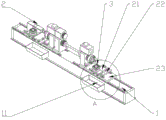
FIG. 1 is a schematic view of the present invention;
FIG. 2 is an enlarged view of portion A of FIG. 1;
fig. 3 is a schematic view of a fixture.
The automatic feeding device comprises a machine frame 1, a material collecting disc 11, a processing part 2, a first carriage 21, a second carriage 22, a third carriage 23, a clamp 3, a motor 31, a base 32, a clamping piece 33, a pressing piece 34, a bolt 341 and a stand column 35.
Detailed Description
The present invention will be further explained with reference to the following embodiments, which are to be understood as illustrative only and not as limiting the scope of the invention, and modifications of the various equivalent forms of the present invention by those skilled in the art after reading the present invention fall within the scope of the appended claims.
It should be noted that: like reference numbers and letters refer to like items in the following figures, and thus, once an item is defined in one figure, it need not be further defined and explained in subsequent figures.
In the description of the present invention, it should be noted that the terms "vertical" and "outer peripheral surface" are used to indicate the position or positional relationship based on the position or positional relationship shown in the drawings, or the position or positional relationship that the product of the present invention is usually placed when in use, and are only for convenience of description and simplification of the description, but do not indicate or imply that the device or element to be referred must have a specific position, be constructed in a specific orientation, and be operated, and therefore should not be construed as limiting the present invention. Furthermore, the terms "first," "second," "third," and the like are used solely to distinguish one from another and are not to be construed as indicating or implying relative importance.
Furthermore, the term "vertical" or the like does not imply that the components are required to be absolutely horizontal or overhanging, but rather may be slightly inclined. For example, "horizontal" merely means that the direction is more horizontal than "vertical" and does not mean that the structure must be perfectly horizontal, but may be slightly inclined.
In the description of the present invention, it should also be noted that, unless otherwise explicitly specified or limited, the terms "disposed," "mounted," "connected," and "connected" are to be construed broadly, e.g., as meaning either a fixed connection, a removable connection, or an integral connection; can be mechanically or electrically connected; they may be connected directly or indirectly through intervening media, or they may be interconnected between two elements. The specific meaning of the above terms in the present invention can be understood in specific cases to those skilled in the art.
As shown in fig. 1-3, a trenchless drill pipe double-ended finishing lathe for drill pipe finishing, comprising:
the device comprises a frame 1, wherein a material collecting disc 11 is arranged on one side of the frame 1;
the machining part 2 is slidably mounted on the rack 1 and located at two ends of the rack 1, and comprises a first carriage 21, a second carriage 22 and a third carriage 23 which are sequentially arranged from top to bottom, the third carriage 23 is connected with the rack 1 and can slide along the drill rod laying direction, the second carriage 22 is slidably mounted on the third carriage 23 and is the same as the third carriage 23 in the moving direction, the first carriage 21 is slidably mounted on the second carriage 22 and can move along the direction perpendicular to the drill rod laying direction, and a cutter for turning and milling the drill rod is further arranged on the first carriage 21. The first carriage 21 moves relative to the second carriage 22, the second carriage 22 moves relative to the third carriage 23, and the finish turning precision can be effectively controlled through grading linkage.
Preferably, the tool is fixedly mounted to the first carriage 21 by means of a clamp 3.
Preferably, the clamp 3 comprises
The driving part comprises a motor 31, and the output end of the motor 31 is connected with a base 32;
the clamping part comprises a clamping piece 33 and a pressing piece 34, the clamping piece 33 is rotatably installed above the base 32, the pressing piece 34 is fixedly installed above the clamping piece 33, a gap is reserved between the pressing piece 34 and the clamping piece 33, through holes penetrating through the pressing piece 34 are formed in the main body of the pressing piece 34 in a matrix mode, and bolts 341 are inserted into the through holes. The clamping piece 33 capable of rotating relative to the base 32 is arranged, so that the structure is reasonable, and the forward and reverse directions of the cutter can be switched at any angle; through having seted up the through-hole through the matrix on compressing tightly 34 main parts, can install many cutters between holder 33 and compressing tightly 34, can realize the switching of different model cutters in the course of working.
Preferably, the inner wall of the through-hole is formed with an internal thread to be matched with the bolt 341. The utility model is convenient for dismounting and mounting various types of cutters.
Preferably, the pressing member 34 and the clamping member 33 are fixedly connected by a pillar 35. It is rational in infrastructure and compress tightly between piece 34 and holder 33 more stable.
Preferably, the clamping member 33 is the same shape as the pressing member 34.
Preferably, the first carriage 21, the second carriage 22 and the third carriage 23 are slidably connected through dovetail grooves, respectively. The structure is reasonable, and the first carriage 21, the second carriage 22 and the third carriage 23 cannot generate vertical displacement by arranging dovetail grooves.
Although the present invention has been described with reference to a preferred embodiment, it should be understood that various changes, substitutions and alterations can be made herein without departing from the spirit and scope of the invention as defined by the appended claims.
It should be noted that the structures, ratios, sizes, and the like shown in the drawings attached to the present specification are only used for matching the disclosure of the present specification, so as to be understood and read by those skilled in the art, and are not used to limit the conditions of the present invention, so that the present invention has no technical essence, and any structural modification, ratio relationship change, or size adjustment should still fall within the range covered by the technical contents disclosed by the present invention without affecting the efficacy and the achievable purpose of the present invention.
Claims (7)
1. The utility model provides a non-excavation drill rod double-end finish turning for the drill rod finish machining, its characterized in that includes:
the device comprises a rack, wherein a material collecting disc is arranged on one side of the rack;
the machining part is slidably mounted on the rack, is positioned at two ends of the rack and comprises a first carriage, a second carriage and a third carriage which are sequentially arranged from top to bottom, the third carriage is connected with the rack and can slide along the direction of laying the drill rods, the second carriage is slidably mounted on the third carriage and has the same movement direction as the third carriage, the first carriage is slidably mounted on the second carriage and can move along the direction perpendicular to the direction of laying the drill rods, and a cutter for turning and milling the drill rods is further arranged on the first carriage.
2. The trenchless drill pipe double-ended finishing block of claim 1, wherein: the cutter is fixedly arranged on the first carriage through a clamp.
3. The trenchless drill pipe double-ended finishing block of claim 2, wherein: the clamp comprises
The driving part comprises a motor, and the output end of the motor is connected with the base;
the clamping part comprises a clamping piece and a pressing piece, the clamping piece is rotatably installed above the base, the pressing piece is fixedly installed above the clamping piece, a gap is reserved between the pressing piece and the clamping piece, through holes penetrating through the pressing piece are formed in the pressing piece body in a matrix mode, and bolts are inserted in the through holes.
4. The trenchless drill pipe double-ended finishing block of claim 3, wherein: and the inner wall of the through hole is provided with an internal thread matched with the bolt.
5. The trenchless drill pipe double-ended finishing block of claim 4, wherein: the pressing piece and the clamping piece are fixedly connected through an upright post.
6. The trenchless drill pipe double-ended finishing block of claim 5, wherein: the clamping piece and the pressing piece are the same in shape.
7. The trenchless drill pipe double-ended finishing block of claim 1, wherein: the first carriage, the second carriage and the third carriage are respectively connected in a sliding mode through dovetail grooves.
Priority Applications (1)
| Application Number | Priority Date | Filing Date | Title |
|---|---|---|---|
| CN202020600559.9U CN212240011U (en) | 2020-04-21 | 2020-04-21 | Trenchless drill rod double-end finish turning machine |
Applications Claiming Priority (1)
| Application Number | Priority Date | Filing Date | Title |
|---|---|---|---|
| CN202020600559.9U CN212240011U (en) | 2020-04-21 | 2020-04-21 | Trenchless drill rod double-end finish turning machine |
Publications (1)
| Publication Number | Publication Date |
|---|---|
| CN212240011U true CN212240011U (en) | 2020-12-29 |
Family
ID=74003218
Family Applications (1)
| Application Number | Title | Priority Date | Filing Date |
|---|---|---|---|
| CN202020600559.9U Active CN212240011U (en) | 2020-04-21 | 2020-04-21 | Trenchless drill rod double-end finish turning machine |
Country Status (1)
| Country | Link |
|---|---|
| CN (1) | CN212240011U (en) |
Cited By (2)
| Publication number | Priority date | Publication date | Assignee | Title |
|---|---|---|---|---|
| CN111360547A (en) * | 2020-04-21 | 2020-07-03 | 扬州黎明钻具有限公司 | A double-head fine turning of a trenchless drill pipe |
| CN113458425A (en) * | 2021-07-04 | 2021-10-01 | 张涛 | Intelligent non-excavation drilling rod double-end finish turning |
-
2020
- 2020-04-21 CN CN202020600559.9U patent/CN212240011U/en active Active
Cited By (2)
| Publication number | Priority date | Publication date | Assignee | Title |
|---|---|---|---|---|
| CN111360547A (en) * | 2020-04-21 | 2020-07-03 | 扬州黎明钻具有限公司 | A double-head fine turning of a trenchless drill pipe |
| CN113458425A (en) * | 2021-07-04 | 2021-10-01 | 张涛 | Intelligent non-excavation drilling rod double-end finish turning |
Similar Documents
| Publication | Publication Date | Title |
|---|---|---|
| CN211661532U (en) | But angle regulation's jig | |
| CN111001990B (en) | Automatic machining process and equipment for stator surface of crankcase | |
| CN201592362U (en) | Hydraulic clamp for milling machine or boring machine | |
| CN210208743U (en) | Machining equipment for machine-building | |
| CN108526494A (en) | A kind of big packet double end turning lathe special plane of new-energy automobile rear axle | |
| CN111468899A (en) | Laser hardening process for thread surface of trenchless drill rod joint | |
| CN211978587U (en) | Abrasion resistance detection device for cutting tool production | |
| CN220825493U (en) | Multi-angle saddle mouth cutting device for pipe | |
| CN219026482U (en) | Auto-parts welding frock | |
| CN216829833U (en) | Crankcase's processing equipment | |
| CN214720674U (en) | Drilling machine capable of drilling inclined hole | |
| CN213889134U (en) | Workpiece limiting mechanism for machine tool machining | |
| CN211867131U (en) | Assembled steel construction building site uses multi-functional rotatory workstation | |
| CN217859993U (en) | Cutter adjusting bracket for metal processing | |
| CN220971305U (en) | Turntable robot welding system | |
| CN214392566U (en) | Steel pipe cutting equipment convenient to adjust | |
| CN2040825U (en) | Fixture for drilling | |
| CN218746296U (en) | Horizontal through-rail multifunctional double-sided lathe | |
| CN219581742U (en) | Special machine tool for numerical control machining of large-size pipe fittings | |
| CN221018851U (en) | Self-adaptive disc milling cutter support | |
| CN211720441U (en) | Metal insert combined auxiliary device for machining motor rotor | |
| CN224254297U (en) | Aluminium alloy milling hole device | |
| CN220407961U (en) | Special sample fixture for double-end-face milling machine | |
| CN2295540Y (en) | Twisting machine | |
| CN222114347U (en) | Frock clamp of supplementary spare and accessory part lateral wall milling and drilling processing |
Legal Events
| Date | Code | Title | Description |
|---|---|---|---|
| GR01 | Patent grant | ||
| GR01 | Patent grant |