CN212218641U - Pushing vegetable cutter - Google Patents
Pushing vegetable cutter Download PDFInfo
- Publication number
- CN212218641U CN212218641U CN201922492386.3U CN201922492386U CN212218641U CN 212218641 U CN212218641 U CN 212218641U CN 201922492386 U CN201922492386 U CN 201922492386U CN 212218641 U CN212218641 U CN 212218641U
- Authority
- CN
- China
- Prior art keywords
- vegetable
- plate
- cutter
- pushing
- layer
- Prior art date
- Legal status (The legal status is an assumption and is not a legal conclusion. Google has not performed a legal analysis and makes no representation as to the accuracy of the status listed.)
- Active
Links
- 235000013311 vegetables Nutrition 0.000 title claims description 99
- 239000000463 material Substances 0.000 claims abstract description 70
- 235000013305 food Nutrition 0.000 claims description 76
- XLYOFNOQVPJJNP-UHFFFAOYSA-N water Substances O XLYOFNOQVPJJNP-UHFFFAOYSA-N 0.000 claims description 32
- 238000005406 washing Methods 0.000 claims description 19
- 125000006850 spacer group Chemical group 0.000 claims description 5
- 238000007599 discharging Methods 0.000 claims description 4
- 230000003068 static effect Effects 0.000 claims description 4
- 230000001141 propulsive effect Effects 0.000 abstract description 2
- 239000002184 metal Substances 0.000 description 12
- 239000002245 particle Substances 0.000 description 4
- 230000000694 effects Effects 0.000 description 3
- 238000010411 cooking Methods 0.000 description 2
- 238000005034 decoration Methods 0.000 description 2
- 238000010586 diagram Methods 0.000 description 2
- 238000009434 installation Methods 0.000 description 2
- 239000008187 granular material Substances 0.000 description 1
- 230000005484 gravity Effects 0.000 description 1
- 238000000034 method Methods 0.000 description 1
- 230000000149 penetrating effect Effects 0.000 description 1
- 238000011282 treatment Methods 0.000 description 1
Images




Landscapes
- Food-Manufacturing Devices (AREA)
Abstract
The utility model provides a bulldoze vegetable-chopper, including first layer net sword, sublayer cutting knife, bulldoze board and controller, controller control bulldozes the board and bulldozes edible material to passing first layer net sword, the sublayer cutting knife cuts the edible material that has passed first layer net sword at first layer net sword back, the quiescent side at the first layer net sword back of sublayer cutting knife, controller control bulldozes the board and bulldozes edible material to the mode that passes first layer net sword for progressively advancing, the controller is at the first layer net sword of adjacent two-step propulsive intermittent type phase control and is removed and return toward this side, first layer net sword drives and just passes the edible material at the net sword back of net and removes then the quiescent meeting of sublayer cutting knife and eat the material and cut. The utility model provides a different vegetable-chopper that bulldozes of technical conception.
Description
Technical Field
The utility model relates to an automatic vegetable-chopper especially relates to a bulldoze vegetable-chopper.
Background
The food material needs to be cut before cooking, and different cutting treatments need to be performed on the food material according to different cooking requirements, for example, the food material is cut into different shapes such as segments, slices, strips and granules. At present common edible material cutting device adopts the cooperation of two-layer cutter in order to realize cutting grain more, particularly, the first layer cutter adopts the net sword usually, and the push pedal bulldozes edible material to the net sword and makes edible material pass the net sword, and the sublayer cutter then cuts the edible material that passes the net sword in order to reach the effect of cutting grain. In order to cut the food material into particles, the food material passing through the grid knife needs to be cut when reaching a certain length of the secondary layer knife, so that the secondary layer knife needs to repeatedly pass through the back of the grid knife to cut, and the secondary layer knife is usually set as a rotary knife in practice, and the rotary knife is driven by a motor to rotate, so that the particle cutting function can be realized by matching with the grid knife.
Disclosure of Invention
The utility model provides a bulldoze vegetable-chopper aims at providing the different hardware architecture who bulldozes the vegetable-chopper of a technical conception, supplies programmers to program the treater wherein to realize the effect the same with current vegetable-chopper.
For realizing above-mentioned purpose, the utility model provides a bulldoze vegetable-chopper, including first layer net sword, sublayer cutting knife, bulldoze board and controller, controller control bulldozes the board and bulldozes edible material to passing first layer net sword, the sublayer cutting knife has passed edible material of first layer net sword at first layer net sword back cutting, the quiescent side at the first layer net sword back of sublayer cutting knife, controller control bulldozes the board and bulldozes edible material to the mode that passes first layer net sword for progressively advancing, the controller is at the first layer net sword of adjacent two-step propulsive intermittent type phase control and is removed and return toward this side, first layer net sword drives and just passes edible material at the net sword back and removes then the quiescent meeting of sublayer cutting knife and eat the material and cut toward this side.
Compared with the prior art, the utility model provides a pair of bulldoze vegetable-chopper, with the side at the static first layer net sword back of sublayer cutting knife, drive through first layer net sword and just pass the edible material at the net sword back and toward this side removal for the static meet and connect edible material of sublayer cutting knife, thereby cut. For current vegetable-chopper fixed first layer sword, make the structure of sublayer sword motion, this kind of bulldoze vegetable-chopper provides the different technical scheme of technical concept, makes the motion of first layer sword, and it is fixed with the sublayer sword, utilizes first layer net sword to drive edible material, makes edible material further cut into different shapes such as section, piece, strip, grain by fixed sublayer sword, has realized the effect the same with current vegetable-chopper.
And the first layer of grid cutter is provided with a plurality of cutters, so that a user does not need to replace the cutters when needing to use different cutters. And the food materials cut by the multiple pairs of cutters are discharged from the openings at the end parts of the vertical shafts, and the food outlets are shared, so that the vegetable cutter is small in size.
Drawings
Fig. 1 is a schematic view of the whole structure of the pushing vegetable cutter of the present invention;
FIG. 2 is a schematic view of the mounting structure of the power putter;
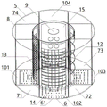
FIG. 3 is a sectional view of the dish of the shredder of FIG. 1;
FIG. 4 is a block diagram of a dicing blade, a slicing blade, a slitting blade, and a backup metal plate of the shredder of FIG. 1;
FIG. 5 is a schematic view of the assembly of the vegetable holding pan and the slicing, slitting and backup metal plates of the shredder of FIG. 1;
FIG. 6 is a block diagram of a vegetable washing tub of the shredder of FIG. 1;
fig. 7 is a schematic structural view of a pushing plate and a driving device of the vegetable cutter shown in fig. 1.
In the figure: 1. mounting plate, 2, electric push rod, 3, mounting sleeve, 4, bearing, 41, bearing seat, 5, vegetable containing plate, 6, annular bottom plate, 61, water permeable hole, 71, spacer, 72, spacer, 73, spacer, 74, spacer, 8 top plate, 9, mounting hole, 101, vegetable containing area, 102, vegetable containing area, 103, vegetable containing area, 104, vegetable containing area, 111, mounting frame, 112, mounting frame, 113, mounting frame, 114, mounting frame, 12, dicing cutter, 13, dicing cutter, 14, slitting cutter, 15, spare metal plate, 16, finger hole, 17, motor, 18, push plate, 19, vegetable washing barrel, 191, water containing part, 192, 20, inner barrel, 21, outer barrel, 30, annular bottom plate, 211, lower half, 212, upper half part, 22, upper material port, 23, hole, 24, water inlet, 25, overflow hole, 26, 27, accommodating part, 24, water inlet, 25, 24, water outlet, 26, 2, accommodating part, 9, water permeable hole, 9, annular cutter, 28, single-shaft sliding table, 29 and lug.
Detailed Description
As shown in figure 1, a bulldoze vegetable-chopper include mounting panel 1, install electric putter 2 on the mounting panel 1, as shown in figure 2, 1 bottom center department of this mounting panel is equipped with hollow installation cover 3, makes electric putter 2 and mounting panel 1 fixed connection in electric putter 2's push rod bottom inserts installation cover 3, electric putter 2 can drive mounting panel 1 and move down and shift up. The bottom end of the mounting sleeve 3 is provided with a bearing 4 and a bearing seat 41, the bearing 4 and the bearing seat 41 enable the mounting sleeve 3 to be connected with a dish containing plate 5, the dish containing plate 5 can move downwards and upwards along with the mounting plate 1 under the driving of the electric push rod 2 and can also rotate around a vertical shaft, and the rotation of the dish containing plate 5 is driven by a motor 17 mounted on the mounting plate 1.
The dish holding plate 5 is structurally shown in fig. 3, the dish holding plate 5 comprises an annular bottom plate 6 serving as a plate bottom, four spacing pieces 71, 72, 73 and 74 are arranged on the annular bottom plate 6, a top plate 8 is arranged above the four spacing pieces 71, 72, 73 and 74, and a hole 9 for mounting the bearing 4 is formed in the top plate 8. The four spacing pieces 71, 72, 73, 74 divide the dish tray 5 into four dish containing areas 101, 102, 103, 104, the four dish containing areas 101, 102, 103, 104 are distributed around the vertical axis, in the state shown in fig. 3, the dish tray 5 is rotated counterclockwise by taking the dish containing area 101 as a starting point, and when the rotation angles are respectively 90 °, 180 °, 270 °, the dish containing areas 102, 103, 104 can be seen. The dish containing plate 5 is further provided with four mounting frames 111, 112, 113 and 114 which respectively correspond to the dish containing areas 101, 102, 103 and 104, taking the mounting frame 111 as an example, the top plate 8 is provided with a convex edge 81 near the vertical axis, the spacing pieces 71 and 74 are respectively provided with convex edges 711 and 741 near the vertical axis, the convex edges 81, 711 and 741 jointly form the mounting frame 111, the mounting frame 111 is positioned between the dish containing area 101 and the vertical axis, and a magnet for adsorbing the cutter is arranged on one side of the mounting frame 111 facing the dish containing area 101.
The cutters include three types, namely a slicing cutter 12, a slicing cutter 13 and a slicing cutter 14, and as shown in fig. 4, the slicing cutter 12, the slicing cutter 14 and the slicing cutter 13 respectively extend into the dish containing areas 103, 102 and 101 and are mounted on mounting frames 113, 112 and 111. The rest dish containing area 104 is used as a spare dish containing area, a cutter is not arranged, and the spare metal plate 15 is arranged on the dish containing area 114 by extending into the dish containing area 101. Since the spare metal plate 15, the dicing cutter 12, the slitting cutter 14 and the slitting cutter 13 are attached to the mounting frames 114, 113, 112 and 111 through magnets, in order to take out the cutters, finger holes are formed in the spare metal plate 15, the dicing cutter 12, the slitting cutter 14 and the slitting cutter 13, taking the slitting cutter 14 as an example, as shown in fig. 5, two finger holes 16 into which fingers can be inserted are formed in the upper portion of the slitting cutter 14, when the slitting cutter 14 needs to be taken out, a hand can be inserted into the vegetable containing area 102 to insert the fingers into the finger holes 16, the fingers hook the slitting cutter 14 and pull outwards to separate the slitting cutter 14 from the mounting frame 112, and the slitting cutter 14 is taken out after being pulled outwards continuously to separate the slitting cutter 14 from the vegetable containing area 102. Since the spare metal plate 15, the dicing cutter 12, the slitting cutter 14 and the slicing cutter 13 are all mounted on the vegetable tray 5, when the electric push rod 2 drives the vegetable tray 5 to move downwards and upwards, the spare metal plate 15, the dicing cutter 12, the slitting cutter 14 and the slicing cutter 13 also move downwards and upwards along with the spare metal plate. Since the spare metal plate 15, the slicing cutter 12, the slitting cutter 14 and the slicing cutter 13 are respectively arranged between the vegetable containing areas 104, 103, 102 and 101 and the vertical shaft, the vegetable containing disc 5 rotates around the vertical shaft of the vegetable containing disc to enable the vegetable containing areas 104, 103, 102 and 101 to reach the pushing station in a time sharing mode, and the spare metal plate 15, the slicing cutter 12, the slitting cutter 14 and the slicing cutter 13 are also aligned to the pushing station in a time sharing mode. The pushing station is aligned with the pushing plate 18, taking the vegetable containing area 102 as an example, when the vegetable containing area 102 moves to the pushing station, the strip cutting tool 14 located between the vegetable containing area 102 and the vertical shaft also moves to a position aligned with the pushing station, the pushing plate 18 extends from the radial outer side of the vegetable containing area 102, the food material placed in the vegetable containing area 102 is pushed towards the strip cutting tool 14, the food material penetrates through the strip cutting tool 14 to enter a reserved space at the vertical shaft, the reserved space is a vegetable outlet area, and the food material is discharged from an opening at the lower end of the vertical shaft after completely penetrating through the strip cutting tool 14.
Since the vegetable containing plate 5 is not provided with an outer side wall at the vegetable containing areas 104, 103, 102, and 101, in order to prevent the food material from falling from the vegetable containing areas 104, 103, 102, and 101 when the vegetable containing plate 5 rotates, the vegetable containing plate 5 is disposed inside the vegetable washing barrel 19 (as shown in fig. 1), the vegetable washing barrel 19 is configured as shown in fig. 6, the vegetable washing barrel 19 includes an inner barrel 20 and an outer barrel 21 sleeved outside the inner barrel 20, and bottoms of the inner barrel 20 and the outer barrel 21 are connected to each other through an annular bottom plate 30, so as to form an annular vegetable washing barrel 19. The space that inner tube 20 encloses is the discharging channel who supplies to eat the material ejection of compact, and inner tube 20 aligns with the vertical axis of flourishing vegetable dish 5, and the diameter of this inner tube 20 is less than the interior circle diameter of flourishing vegetable dish 5 (being the interior circle diameter of annular bottom plate 6), and the diameter of urceolus 21 is greater than the excircle diameter of flourishing vegetable dish 5 (being the excircle diameter of annular bottom plate 6), so flourishing vegetable dish 5 holding provides the lateral wall for flourishing vegetable dish 5 by urceolus 21 in washing bucket 19. The height of the inner cylinder 20 is half of that of the outer cylinder 21, the lower half part of the vegetable washing barrel 19 is provided with the inner cylinder 20 and the outer cylinder 21 at the same time and is called a water containing part 191, the upper half part is provided with the outer cylinder 21 only and is called a containing part 192, the part of the outer cylinder 21 corresponding to the water containing part 191 is called a lower half part 211, and the part of the outer cylinder 21 corresponding to the containing part 192 is called an upper half part 212.
A water inlet hole 24, an overflow hole 25 and a water discharge hole 26 are sequentially formed in the outer cylinder 21 of the water containing unit 191 from top to bottom, the water inlet hole 24 and the overflow hole 25 are positioned at the upper portion of the water containing unit 191, and the water discharge hole 26 is positioned at the lower portion of the water containing unit 191. Water is injected into the vegetable washing barrel 19 from the water inlet hole 24, the electric push rod 2 drives the vegetable containing plate 5 to move downwards, so that the vegetable containing plate 5 is immersed into the water containing part 191 of the vegetable washing barrel 19, and therefore the food materials in the vegetable containing areas 101, 102, 103 and 104 are cleaned. In order to facilitate water to be immersed into the vegetable containing areas 101, 102, 103 and 104, densely distributed water permeable holes 61 are formed on the annular bottom plate 6 corresponding to the vegetable containing areas 101, 102, 103 and 104. In order to wash the food more thoroughly, the food tray 5 can be driven by the motor 17 to rotate to make the food fully contact with the water under the condition that the food tray 5 is immersed in the water containing part 191. After the food material is washed, the electric push rod 2 drives the dish tray 5 to move up and away from the water containing part 191 to move to the water containing part 192, and the water in the water containing part 191 is discharged through the water discharge hole 26.
In order to facilitate the food material to be put in, the upper half part 212 of the outer barrel 21 is provided with a feeding opening 22, the shape of the feeding opening 22 is the same as the opening shape of the vegetable containing areas 104, 103, 102 and 101, the vegetable washing barrel 19 is fixed and does not rotate, and the vegetable containing plate 5 rotates around the vertical axis to enable the vegetable containing areas 104, 103, 102 and 101 to be aligned with the feeding opening 22 in a time sharing mode. The upper half 212 of the outer cylinder 21 is further provided with a hole 23 for the pushing plate 18 to extend into, taking the dish-holding area 101 as an example, when the dish-holding plate 5 is located at the containing part 192, the motor drives the dish containing plate 5 to rotate around the vertical axis to make the dish containing area 101 align with the feeding hole 22, the food materials to be put in pass through the feeding hole 22 to enter the dish containing area 101, then the vegetable containing area 101 moves to the pushing station when the vegetable containing plate 5 continues to rotate, the vegetable containing area 101 positioned at the pushing station is aligned with the hole 23, the slitting cutter 14 arranged between the vegetable containing area 101 and the vertical shaft also moves to the position aligned with the pushing station, the pushing plate 18 extends into the vegetable containing area 101 from the radial outer side of the vegetable containing plate 5 through the hole 23 to push the food materials in the vegetable containing area 10 inwards, the food materials pass through the slitting cutter 14 and enter the reserved space at the vertical shaft, and the food materials completely pass through the slitting cutter 14 and then fall into the discharging channel from the reserved space, and then are discharged from the discharging channel. If a user only needs to clean food materials and does not need to cut the food materials, the spare metal plate 15 arranged on the mounting frame 114 can be taken out, the food containing tray 5 rotates to enable the food containing area 104 to be aligned with the feeding hole 22, so that the food materials are placed in the food containing area 104, then the electric push rod 2 drives the food containing tray 5 to move downwards, so that the food containing tray 5 is immersed into the water containing part 191 of the food washing barrel 19, the motor 17 drives the food containing tray 5 to rotate to enable the food materials to be fully contacted with water, after the food materials are cleaned, the electric push rod 2 drives the food containing tray 5 to move upwards to leave the water containing part 191 to move to the containing part 192, the motor 17 drives the food containing tray 5 to rotate to enable the food containing area 104 to move to a pushing station, the food containing area 104 is aligned with the hole 23, the pushing plate 18 penetrates through the hole 23 and extends into the food containing area 101 from the radial outer side of the food containing tray 5, the food materials placed in the food containing area 10 are pushed inwards, then falls into a blanking channel from the blank space so as to perform blanking.
Since the food material cut into strips needs to be further cut by the food material cutting, the embodiment is provided with an annular knife 27 with an upward edge on the top of the inner cylinder 20 of the vegetable washing barrel 19, and the annular knife 27 serves as a secondary layer cutting knife to cut the food materials 12, 13, 14 which have passed through the knife at the back of the knife 12, 13, 14. Taking food material dicing as an example, after the food material is cleaned, the motor 17 drives the food tray 5 to rotate to move the food containing area 102 to the pushing station, the food containing area 102 is aligned with the hole 23, the controller controls the pushing plate 18 to extend into the food containing area 102 from the radial outer side of the food containing tray 5 through the hole 23, the food material placed in the food containing area 10 is pushed inwards in a gradually advancing manner, so that a part of the food material passes through the slitting cutter 14 to enter the space at the vertical axis, then in the interval period of two adjacent advancing steps, the controller controls the pushing plate 18 to leave the food containing area 102 and return to the original position, the electric push rod 2 drives the food tray 5 to move downwards, the slitting cutter 14 arranged on the food tray 5 moves downwards along with the movement, the food material passing through the slitting cutter 14 moves downwards along with the movement, in the process that the food material follows the downward movement, the annular cutter 27 with the upward edge positioned at the top of the inner cylinder 20 is still contacted with the food, the food material passing through the slitting cutter 14 is cut into particles, then the electric push rod 2 drives the vegetable containing plate 5 to move upwards to enable the vegetable containing plate 5 to return to the containing part 192, the push plate 18 enters the vegetable containing area 102 again, and the actions are repeated until all the food material is cut into particles, and the cutting is finished.
As shown in fig. 7, the pushing plate 18 is driven by a driving device, which is a single-shaft sliding table 28, and a protrusion 29 is provided on one side of the pushing plate 18 facing the vertical shaft of the vegetable tray 5, and the protrusion 29 can push the food out of the cutters 12, 13, 14. Taking the slitting cutter 14 as an example, because the slitting cutter 14 has a certain thickness, when the food material passes through the slitting cutter 14, a part of the food material is clamped inside the slitting cutter 14, under normal conditions, when the food material passes through the slitting cutter 14, a longer part of the food material enters the vertical shaft empty part, only a small part of the food material is embedded in the slitting cutter 14, under the action of gravity, the food material can automatically separate from the slitting cutter 14 and enter the discharge channel from the vertical shaft empty part, but sometimes the food material can be clamped in the slitting cutter 14 and cannot automatically fall off, the convex block 29 on the pushing plate 18 can be inserted into the slitting cutter 14, the food material clamped in the slitting cutter 14 is pushed out, and the food material falls off. The foregoing is a preferred embodiment of the present invention, and it should be noted that, for those skilled in the art, a plurality of improvements and decorations can be made without departing from the principle of the present invention, and these improvements and decorations are also considered as the protection scope of the present invention.
Claims (10)
1. Bulldoze the vegetable-chopper, including first layer net sword, sublayer cutting knife, bulldoze board and controller, the bulldoze board is connected to the controller, bulldozes the board and can bulldoze edible material to passing first layer net sword, and the sublayer cutting knife has passed the edible material of first layer net sword at first layer net sword back cutting, characterized by: the static side at the first layer net sword back of sublayer cutting knife, first layer net sword can move toward this side and return, and first layer net sword drives and just passes the edible material toward this side removal at the net sword back, and the static meet of sublayer cutting knife is eaten the material and is cut.
2. A push shredder according to claim 1, wherein the controller controls the push plate to retract during intermittent periods.
3. A pushing vegetable cutter as claimed in claim 2, comprising a vegetable containing plate rotating around its own vertical axis, wherein a plurality of vegetable containing areas are distributed on the vegetable containing plate around the vertical axis, the first layer of grid knives have a plurality of different kinds of pairs, the plurality of pairs of first layer grid knives are respectively installed on the vegetable containing plate corresponding to the plurality of vegetable containing areas and vertically arranged between the vegetable containing areas and the vertical axis, a pushing plate corresponds to the plurality of vegetable containing areas and the plurality of pairs of knives, the vegetable containing plate rotates around its own vertical axis to make each vegetable containing area reach a pushing station in a time-sharing manner, each pair of first layer grid knives rotate along with the vegetable containing areas to align with the pushing station in a time-sharing manner, the pushing plate extends into the vegetable containing area which has reached the pushing station, the pushing plate pushes the food material located at the pushing station toward the vertical axis to pass through the first layer grid knives, the vertical axis leaves empty space for the food material to enter after passing through the first layer grid knives, and the vertical axis opens at the end of the.
4. A push vegetable cutter as claimed in claim 3 wherein the plurality of pairs of first grid knives are each detachably mounted on a serving tray.
5. A push shredder as claimed in claim 3, wherein the push plate extends radially outwardly of the serving area.
6. A push vegetable cutter as claimed in claim 3 wherein the lower end of the vertical shaft is open for the discharge of cut material.
7. A push vegetable cutter as claimed in claim 6 wherein the vegetable tray is provided with spacers for separating the vegetable areas, the tray bottom is provided with water holes for water to pass through, a vegetable washing barrel is arranged below the vegetable tray, the vegetable tray can move down into and up out of the vegetable washing barrel, the vegetable washing barrel comprises an inner barrel and an outer barrel sleeved outside the inner barrel, the bottom of the inner barrel and the bottom of the outer barrel are connected with each other through a ring-shaped bottom plate to form a ring-shaped vegetable washing barrel, the inner barrel is aligned with the vertical shaft, the space enclosed by the inner barrel is a discharge channel for discharging the cut food, and the top of the inner barrel is provided with a ring-shaped knife with an upward edge as the secondary layer cutting knife.
8. A pushing vegetable cutter as claimed in claim 7, wherein the vegetable containing plate is not provided with an outer side wall at the vegetable containing area, the outer barrel of the vegetable washing barrel extends upwards to be sleeved on the outer side of the vegetable containing plate to provide the outer side wall for the vegetable containing area, the vegetable washing barrel is fixed and does not rotate, the outer barrel is provided with a feeding port, the vegetable containing plate rotates around a vertical shaft to enable each vegetable containing area to be aligned with the feeding port, the outer barrel is provided with a hole for a pushing plate to extend into, and the vegetable containing area located at the pushing station is aligned with the hole.
9. A push vegetable cutter as claimed in claim 7 or claim 8 wherein the controller also controls the dish to move down into and up out of the tub.
10. A push shredder according to claim 2, characterised in that the push plate is moved by drive means.
Priority Applications (1)
| Application Number | Priority Date | Filing Date | Title |
|---|---|---|---|
| CN201922492386.3U CN212218641U (en) | 2019-12-30 | 2019-12-30 | Pushing vegetable cutter |
Applications Claiming Priority (1)
| Application Number | Priority Date | Filing Date | Title |
|---|---|---|---|
| CN201922492386.3U CN212218641U (en) | 2019-12-30 | 2019-12-30 | Pushing vegetable cutter |
Publications (1)
| Publication Number | Publication Date |
|---|---|
| CN212218641U true CN212218641U (en) | 2020-12-25 |
Family
ID=73901782
Family Applications (1)
| Application Number | Title | Priority Date | Filing Date |
|---|---|---|---|
| CN201922492386.3U Active CN212218641U (en) | 2019-12-30 | 2019-12-30 | Pushing vegetable cutter |
Country Status (1)
| Country | Link |
|---|---|
| CN (1) | CN212218641U (en) |
Cited By (1)
| Publication number | Priority date | Publication date | Assignee | Title |
|---|---|---|---|---|
| CN111015777A (en) * | 2019-12-30 | 2020-04-17 | 广州富港万嘉智能科技有限公司 | Pushing vegetable cutter |
-
2019
- 2019-12-30 CN CN201922492386.3U patent/CN212218641U/en active Active
Cited By (1)
| Publication number | Priority date | Publication date | Assignee | Title |
|---|---|---|---|---|
| CN111015777A (en) * | 2019-12-30 | 2020-04-17 | 广州富港万嘉智能科技有限公司 | Pushing vegetable cutter |
Similar Documents
| Publication | Publication Date | Title |
|---|---|---|
| CN211867946U (en) | Pushing vegetable cutter | |
| CN109702779A (en) | A kind of apples peeling slice all-in-one machine | |
| CN111230936B (en) | Sweet potato slicing device for food processing | |
| KR20110120681A (en) | Multi purpose stripper | |
| TW201532570A (en) | Strainer device | |
| CN209615599U (en) | A kind of apples peeling slice all-in-one machine | |
| CN212123480U (en) | Pushing vegetable cutter | |
| CN211867948U (en) | Pushing vegetable cutter | |
| CN111015777A (en) | Pushing vegetable cutter | |
| CN209812453U (en) | Automatic cutting device is used in pickled vegetable processing | |
| CN110877356A (en) | Pushing vegetable cutter | |
| CN111015776A (en) | Pushing vegetable cutter | |
| CN211867947U (en) | Pushing vegetable cutter | |
| CN211867949U (en) | Pushing vegetable cutter | |
| CN112092060B (en) | Anti-mildew processing technology for poria cocos | |
| CN211867941U (en) | Pushing vegetable cutter | |
| CN211867943U (en) | Pushing vegetable cutter | |
| CN219926173U (en) | Food processor capable of throwing away food materials | |
| CN111015778A (en) | A push vegetable cutter | |
| CN108185449B (en) | Hawaii fruit notching device | |
| CN219846239U (en) | Food shredding device and food processor | |
| CN111015773A (en) | Pushing vegetable cutter | |
| CN212382061U (en) | potato processor | |
| CN215687165U (en) | Food processor | |
| CN211867944U (en) | Pushing vegetable cutter |
Legal Events
| Date | Code | Title | Description |
|---|---|---|---|
| GR01 | Patent grant | ||
| GR01 | Patent grant |