CN212202518U - A high temperature resistant centrifugal fire smoke exhaust fan - Google Patents
A high temperature resistant centrifugal fire smoke exhaust fan Download PDFInfo
- Publication number
- CN212202518U CN212202518U CN202020858713.2U CN202020858713U CN212202518U CN 212202518 U CN212202518 U CN 212202518U CN 202020858713 U CN202020858713 U CN 202020858713U CN 212202518 U CN212202518 U CN 212202518U
- Authority
- CN
- China
- Prior art keywords
- fixedly installed
- wall
- fan
- smoke exhaust
- exhaust fan
- Prior art date
- Legal status (The legal status is an assumption and is not a legal conclusion. Google has not performed a legal analysis and makes no representation as to the accuracy of the status listed.)
- Expired - Fee Related
Links
Images


Landscapes
- Structures Of Non-Positive Displacement Pumps (AREA)
Abstract
本实用新型公开了一种耐高温的离心式消防排烟风机,包括风机本体,所述风机本体外壁固定安装有排烟通道,所述风机本体右端固定安装有吸气盘,所述风机本体内部转动安装有第一转动体,所述第一转动体外壁固定安装有第一扇叶,所述风机本体左端固定安装有外壳,所述外壳后端固定安装有基座,所述基座上端固定安装有驱动电机,所述外壳外壁固定安装有进水通道和出水通道。该耐高温的离心式消防排烟风机,通过设置降温体,实现了对风机本体快速降温的效果,利于风机本体在高温环境下长时间工作,通过限位体的设置,实现了对进水管和出水管限位固定的效果,利于该排烟风机的运输工作,提高了整体结构的稳定性。
The utility model discloses a high-temperature-resistant centrifugal fire-fighting smoke exhaust fan, comprising a fan body, a smoke exhaust channel is fixedly installed on the outer wall of the fan body, a suction plate is fixedly installed at the right end of the fan body, and the interior of the fan body is A first rotating body is rotatably installed, a first fan blade is fixedly installed on the outer wall of the first rotating body, a casing is fixedly installed at the left end of the fan body, a base is fixedly installed at the rear end of the casing, and the upper end of the base is fixed A drive motor is installed, and a water inlet channel and a water outlet channel are fixedly installed on the outer wall of the casing. The high-temperature-resistant centrifugal fire-fighting smoke exhaust fan is provided with a cooling body to achieve the effect of rapidly cooling the fan body, which is conducive to the fan body working in a high temperature environment for a long time. The effect of limiting and fixing the water outlet pipe is beneficial to the transportation of the smoke exhaust fan and improves the stability of the overall structure.
Description
技术领域technical field
本实用新型涉及消防设备技术领域,具体为一种耐高温的离心式消防排烟风机。The utility model relates to the technical field of fire-fighting equipment, in particular to a high-temperature-resistant centrifugal fire-fighting smoke exhaust fan.
背景技术Background technique
离心风机是依靠输入的机械能,提高气体压力并排送气体的机械,它是一种从动的流体机械,离心风机广泛用于工厂、矿井、隧道、冷却塔、车辆、船舶和建筑物的通风、排尘和冷却,锅炉和工业炉窑的通风和引风,空气调节设备和家用电器设备中的冷却和通风,谷物的烘干和选送,风洞风源和气垫船的充气和推进等,风机广泛用于工厂、矿井、隧道、冷却塔、车辆、船舶和建筑物的通风、排尘和冷却,锅炉和工业炉窑的通风和引风,空气调节设备和家用电器设备中的冷却和通风,谷物的烘干和选送,风洞风源和气垫船的充气和推进等。Centrifugal fan is a machine that relies on input mechanical energy to increase gas pressure and discharge gas. It is a driven fluid machine. Centrifugal fans are widely used in factories, mines, tunnels, cooling towers, vehicles, ships and buildings. Ventilation, Dust extraction and cooling, ventilation and drafting of boilers and industrial furnaces, cooling and ventilation in air-conditioning equipment and household appliances, drying and selection of grains, wind tunnel air sources and inflation and propulsion of hovercraft, etc. For ventilation, dust extraction and cooling in factories, mines, tunnels, cooling towers, vehicles, ships and buildings, ventilation and drafting in boilers and industrial kilns, cooling and ventilation in air conditioning equipment and household appliances, grains The drying and selection of the wind tunnel and the inflation and propulsion of the hovercraft, etc.
排烟风机在用于消防时,常用于高温区域,现有的多数离心式消防排烟风机不具备降温装置,无法在风机运行时对风机进行快速降温,为此,我们提出一种耐高温的离心式消防排烟风机。When the exhaust fan is used for fire fighting, it is often used in high temperature areas. Most of the existing centrifugal fire exhaust fans do not have a cooling device and cannot quickly cool the fan when the fan is running. Therefore, we propose a high temperature resistant exhaust fan. Centrifugal fire exhaust fan.
实用新型内容Utility model content
本实用新型的目的在于提供一种耐高温的离心式消防排烟风机,以解决上述背景技术中提出的现有的多数离心式消防排烟风机不具备降温装置,无法在风机运行时对风机进行快速降温的问题。The purpose of this utility model is to provide a high-temperature resistant centrifugal fire-fighting smoke exhaust fan, so as to solve the problem that most of the existing centrifugal fire-fighting smoke exhaust fans proposed in the above-mentioned background technology do not have a cooling device and cannot perform cooling on the fan when the fan is running. The problem of rapid cooling.
为实现上述目的,本实用新型提供如下技术方案:一种耐高温的离心式消防排烟风机,包括风机本体,所述风机本体外壁固定安装有排烟通道,所述风机本体右端固定安装有吸气盘,所述风机本体内部转动安装有第一转动体,所述第一转动体外壁固定安装有第一扇叶,所述风机本体左端固定安装有外壳,所述外壳后端固定安装有基座,所述基座上端固定安装有驱动电机,所述外壳外壁固定安装有进水通道和出水通道。In order to achieve the above purpose, the present utility model provides the following technical solutions: a high-temperature resistant centrifugal fire-fighting smoke exhaust fan, comprising a fan body, a smoke exhaust channel is fixedly installed on the outer wall of the fan body, and a suction channel is fixedly installed at the right end of the fan body. Air pan, a first rotating body is rotatably installed inside the fan body, a first fan blade is fixedly installed on the outer wall of the first rotating body, a casing is fixedly installed at the left end of the fan body, and a base is fixedly installed at the rear end of the casing. A drive motor is fixedly installed on the upper end of the base, and a water inlet channel and a water outlet channel are fixedly installed on the outer wall of the casing.
优选的,所述进水通道内壁固定安装有进水管,所述基座前端固定安装有第一限位体和第二限位体,所述进水管外壁与第一限位体内壁相互连接,所述出水通道内壁固定安装有出水管,所述出水管外壁与第二限位体内壁相互连接。Preferably, a water inlet pipe is fixedly installed on the inner wall of the water inlet channel, a first limiting body and a second limiting body are fixedly installed at the front end of the base, and the outer wall of the water inlet pipe is connected to the inner wall of the first limiting body. A water outlet pipe is fixedly installed on the inner wall of the water outlet channel, and the outer wall of the water outlet pipe and the inner wall of the second limiter are connected to each other.
优选的,所述外壳内壁固定安装有降温体,所述降温体内部固定开设有第一槽体,所述降温体内部转动安装有第二转动体,所述第二转动体外壁固定安装有第二扇叶。Preferably, a cooling body is fixedly installed on the inner wall of the casing, a first groove body is fixedly opened inside the cooling body, a second rotating body is rotatably installed inside the cooling body, and a second rotating body is fixedly installed on the outer wall of the second rotating body. Two leaves.
优选的,所述第二转动体内壁固定安装有卡接件,所述卡接件内壁固定安装有第一连接体。Preferably, the inner wall of the second rotator is fixedly mounted with a clamping piece, and the inner wall of the clamping piece is fixedly mounted with a first connecting body.
优选的,所述风机本体内部固定开设有第二槽体,所述第二槽体与排烟通道相互贯通,所述第一扇叶截面呈“L”型结构。Preferably, a second groove body is fixedly opened inside the fan body, the second groove body and the smoke exhaust passage communicate with each other, and the cross section of the first fan blade has an "L" shape structure.
优选的,所述第一转动体左端面呈凹型结构,所述第一转动体左端中央固定安装有第二连接体,所述第二连接体与第一连接体内壁处于同平面。Preferably, the left end surface of the first rotating body is in a concave structure, a second connecting body is fixedly installed in the center of the left end of the first rotating body, and the second connecting body and the inner wall of the first connecting body are on the same plane.
与现有技术相比,本实用新型的有益效果是:Compared with the prior art, the beneficial effects of the present utility model are:
1、该耐高温的离心式消防排烟风机,通过设置降温体,实现了对风机本体快速降温的效果,利于风机本体在高温环境下长时间工作,通过限位体的设置,实现了对进水管和出水管限位固定的效果,利于该排烟风机的运输工作,提高了整体结构的稳定性;1. The high-temperature-resistant centrifugal fire-fighting smoke exhaust fan is equipped with a cooling body to achieve a rapid cooling effect on the fan body, which is beneficial for the fan body to work in a high temperature environment for a long time. The effect of limiting and fixing the water pipe and the water outlet pipe is beneficial to the transportation of the exhaust fan and improves the stability of the overall structure;
2、该耐高温的离心式消防排烟风机,通过第一扇叶截面呈“L”型结构的设置,以及降温体左右两端面为圆四分之三结构的设置,实现了换热降温效果的同时避免了烟气大面积进入降温体,保持了排烟效率,利于排烟工作的进行;2. The high-temperature-resistant centrifugal fire-fighting exhaust fan achieves the effect of heat exchange and cooling through the setting of the first fan blade section in an "L"-shaped structure, and the setting of the left and right ends of the cooling body with a three-quarter circle structure. At the same time, it prevents the flue gas from entering the cooling body in a large area, maintains the exhaust efficiency, and facilitates the exhaust work;
3、该耐高温的离心式消防排烟风机,通过设置第一连接体和第二连接体,实现了两个连接体分别与驱动电机转轴相互连接的效果,两个连接体处于同平面的设置实现了稳定转动,通过卡接件的设置,提高了第二转动体的转动稳定性,第二扇叶的设置实现了降温体内部气流流动的效果,利于快速降温的进行。3. The high temperature resistant centrifugal fire-fighting smoke exhaust fan, by setting the first connecting body and the second connecting body, realizes the effect that the two connecting bodies are connected with the rotating shaft of the driving motor respectively, and the two connecting bodies are arranged on the same plane Stable rotation is achieved, and the rotation stability of the second rotor is improved through the arrangement of the clips, and the arrangement of the second fan blades realizes the effect of air flow inside the cooling body, which is conducive to rapid cooling.
附图说明Description of drawings
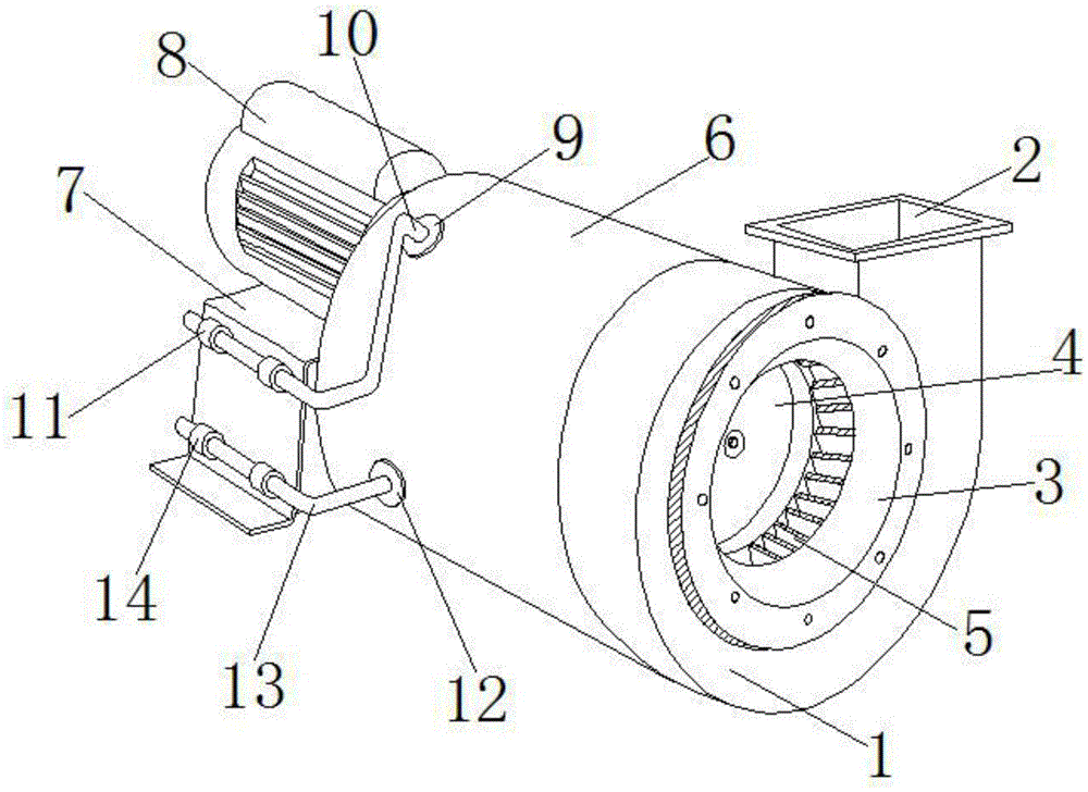
图1为本实用新型立体结构示意图;1 is a schematic diagram of the three-dimensional structure of the present utility model;
图2为本实用新型降温体结构示意图;Fig. 2 is the structural schematic diagram of the cooling body of the present invention;
图3为本实用新型风机本体和吸气盘内部截面结构示意图。3 is a schematic diagram of the internal cross-sectional structure of the fan body and the suction tray of the present invention.
图中:1、风机本体;2、排烟通道;3、吸气盘;4、第一转动体;5、第一扇叶;6、外壳;7、基座;8、驱动电机;9、进水通道;10、进水管;11、第一限位体;12、出水通道;13、出水管;14、第二限位体;15、降温体;16、第一槽体;17、第二转动体;18、第二扇叶;19、卡接件;20、第一连接体;21、第二槽体;22、第二连接体。In the figure: 1. Fan body; 2. Smoke exhaust channel; 3. Suction plate; 4. First rotating body; 5. First fan blade; 6. Shell; 7. Base; 8. Drive motor; 9. water inlet channel; 10, water inlet pipe; 11, first limit body; 12, water outlet channel; 13, water outlet pipe; 14, second limit body; 15, cooling body; 16, first tank body; 17, first 2. The rotating body; 18, the second fan blade; 19, the clamping part; 20, the first connecting body; 21, the second groove body; 22, the second connecting body.
具体实施方式Detailed ways
下面将结合本实用新型实施例中的附图,对本实用新型实施例中的技术方案进行清楚、完整地描述,显然,所描述的实施例仅仅是本实用新型一部分实施例,而不是全部的实施例。基于本实用新型中的实施例,本领域普通技术人员在没有做出创造性劳动前提下所获得的所有其他实施例,都属于本实用新型保护的范围。The technical solutions in the embodiments of the present utility model will be clearly and completely described below with reference to the accompanying drawings in the embodiments of the present utility model. Obviously, the described embodiments are only a part of the embodiments of the present utility model, rather than all the implementations. example. Based on the embodiments of the present invention, all other embodiments obtained by those of ordinary skill in the art without creative work fall within the protection scope of the present invention.
请参阅图1-3,本实用新型提供一种技术方案:一种耐高温的离心式消防排烟风机,包括风机本体1,风机本体1外壁固定安装有排烟通道2,风机本体1右端固定安装有吸气盘3,风机本体1内部转动安装有第一转动体4,第一转动体4外壁固定安装有第一扇叶5,风机本体1左端固定安装有外壳6,外壳6后端固定安装有基座7,基座7上端固定安装有驱动电机8,外壳6外壁固定安装有进水通道9和出水通道12。1-3, the present utility model provides a technical solution: a high temperature resistant centrifugal fire-fighting smoke exhaust fan, comprising a fan body 1, a
进一步的,进水通道9内壁固定安装有进水管10,基座7前端固定安装有第一限位体11和第二限位体14,进水管10外壁与第一限位体11内壁相互连接,出水通道12内壁固定安装有出水管13,出水管13外壁与第二限位体14内壁相互连接,两个限位体的设置实现了对进水管10和出水管13限位固定的效果,提高了排烟风机在运输时的稳定性。Further, a
进一步的,外壳6内壁固定安装有降温体15,降温体15内部固定开设有第一槽体16,降温体15内部转动安装有第二转动体17,第二转动体17外壁固定安装有第二扇叶18,外壳6的设置利于降温体15的安装和拆卸,检修方便。Further, a
进一步的,第二转动体17内壁固定安装有卡接件19,卡接件19内壁固定安装有第一连接体20,卡接件19的设置提高了第二转动体17的转动效果,利于稳定。Further, the inner wall of the second rotating
进一步的,风机本体1内部固定开设有第二槽体21,第二槽体21与排烟通道2相互贯通,第一扇叶5截面呈“L”型结构,实现了排烟效果的同时避免了烟气大面积进入第一槽体16,保持了排烟效率。Further, a
进一步的,第一转动体4左端面呈凹型结构,第一转动体4左端中央固定安装有第二连接体22,第二连接体22与第一连接体20内壁处于同平面,第二连接体22和第一连接体20皆与驱动电机8的转轴相互连接,两个连接体同平面的设置利于稳定转动。Further, the left end face of the first rotating
工作原理:首先,使用软管连接进水管10,将软管的另一端接在水龙头上,将另一根软管连接出水管13,将另一根软管的另一端接至排烟风机外部的合理位置,打开水龙头向进水管10中加水,启动驱动电机8,使第一扇叶5和第二扇叶18同时转动,即可实现排风效果,在排风过程中,热量和部分热风从第一扇叶5的间隙中进入第一槽体16,热量和热风通过冷水和第二扇叶18的转动作用加速冷却,带走热量,实现换热和降温效果,实现了排烟风机在高温环境下长时间的工作。Working principle: First, use a hose to connect the
最后应当说明的是,以上内容仅用以说明本实用新型的技术方案,而非对本实用新型保护范围的限制,本领域的普通技术人员对本实用新型的技术方案进行的简单修改或者等同替换,均不脱离本实用新型技术方案的实质和范围。Finally, it should be noted that the above content is only used to illustrate the technical solution of the present invention, rather than limiting the protection scope of the present invention. Without departing from the essence and scope of the technical solution of the present invention.
Claims (6)
Priority Applications (1)
| Application Number | Priority Date | Filing Date | Title |
|---|---|---|---|
| CN202020858713.2U CN212202518U (en) | 2020-05-20 | 2020-05-20 | A high temperature resistant centrifugal fire smoke exhaust fan |
Applications Claiming Priority (1)
| Application Number | Priority Date | Filing Date | Title |
|---|---|---|---|
| CN202020858713.2U CN212202518U (en) | 2020-05-20 | 2020-05-20 | A high temperature resistant centrifugal fire smoke exhaust fan |
Publications (1)
| Publication Number | Publication Date |
|---|---|
| CN212202518U true CN212202518U (en) | 2020-12-22 |
Family
ID=73817370
Family Applications (1)
| Application Number | Title | Priority Date | Filing Date |
|---|---|---|---|
| CN202020858713.2U Expired - Fee Related CN212202518U (en) | 2020-05-20 | 2020-05-20 | A high temperature resistant centrifugal fire smoke exhaust fan |
Country Status (1)
| Country | Link |
|---|---|
| CN (1) | CN212202518U (en) |
Cited By (3)
| Publication number | Priority date | Publication date | Assignee | Title |
|---|---|---|---|---|
| CN114033728A (en) * | 2021-10-21 | 2022-02-11 | 山东奇虎空调设备集团有限公司 | Fire-fighting smoke exhaust fan |
| CN114046199A (en) * | 2021-10-29 | 2022-02-15 | 无锡曲速智能科技有限公司 | Special fan power assembly of sanitation car |
| CN121322420A (en) * | 2025-11-28 | 2026-01-13 | 湖北三峰透平装备股份有限公司 | A high-temperature gas conveying fan |
-
2020
- 2020-05-20 CN CN202020858713.2U patent/CN212202518U/en not_active Expired - Fee Related
Cited By (5)
| Publication number | Priority date | Publication date | Assignee | Title |
|---|---|---|---|---|
| CN114033728A (en) * | 2021-10-21 | 2022-02-11 | 山东奇虎空调设备集团有限公司 | Fire-fighting smoke exhaust fan |
| CN114033728B (en) * | 2021-10-21 | 2024-03-15 | 山东奇虎空调设备集团有限公司 | Fire control smoke exhaust fan |
| CN114046199A (en) * | 2021-10-29 | 2022-02-15 | 无锡曲速智能科技有限公司 | Special fan power assembly of sanitation car |
| CN114046199B (en) * | 2021-10-29 | 2023-03-07 | 无锡曲速智能科技有限公司 | Special fan power assembly of sanitation car |
| CN121322420A (en) * | 2025-11-28 | 2026-01-13 | 湖北三峰透平装备股份有限公司 | A high-temperature gas conveying fan |
Similar Documents
| Publication | Publication Date | Title |
|---|---|---|
| CN113124463B (en) | Kitchen air conditioning system | |
| CN106637872B (en) | Clothes dryer | |
| CN106403033A (en) | Cabinet air conditioner, air-conditioner and cabinet air conditioner air outlet control method | |
| CN206545597U (en) | A kind of low noise piping lane blower fan | |
| CN211288166U (en) | Textile fan | |
| CN111577636A (en) | Breed and use low noise centrifugal fan | |
| CN206160301U (en) | Kitchen air conditioner | |
| CN205825236U (en) | Wall-hanging air conditioner indoor unit and air-conditioner | |
| CN110529404A (en) | A kind of high-efficiency and energy-saving type cfentrifugal blower | |
| CN207906159U (en) | A kind of heat power plant boiler air-introduced machine | |
| CN215805258U (en) | Double-air-inlet centrifugal ventilator | |
| CN216343073U (en) | Centrifugal force supply structure of centrifugal fire-fighting smoke exhaust fan | |
| CN201180688Y (en) | Heat circulating fan | |
| CN110793132A (en) | Heat exchange device and kitchen air conditioning system provided with same | |
| CN210949204U (en) | Environmentally friendly cooling fan | |
| CN110608182B (en) | Environmentally friendly cooling fan | |
| CN208763997U (en) | A kind of novel smoke exhaust flow-mixing blower fan | |
| CN208138204U (en) | Four sides air inlet volute structure | |
| CN220227220U (en) | Centrifugal fan of air compressor room | |
| CN208294805U (en) | Embedded water stove fan dries by fire | |
| CN215633846U (en) | A double-shaft direct-connected multi-impeller centrifugal compressor structure | |
| CN216384252U (en) | A steam-electric dual-drive induced draft fan flue that reduces the resistance of the flue gas system | |
| CN216361065U (en) | High-efficiency energy-saving steam-electricity dual-drive induced draft fan assembly | |
| CN216894983U (en) | Multifunctional draught fan for boiler of thermal power plant | |
| CN217999955U (en) | Detachable double-port fan hub cover |
Legal Events
| Date | Code | Title | Description |
|---|---|---|---|
| GR01 | Patent grant | ||
| GR01 | Patent grant | ||
| CF01 | Termination of patent right due to non-payment of annual fee | ||
| CF01 | Termination of patent right due to non-payment of annual fee |
Granted publication date: 20201222 |