CN212200967U - Hanging curtain hanging sheet mounting structure - Google Patents
Hanging curtain hanging sheet mounting structure Download PDFInfo
- Publication number
- CN212200967U CN212200967U CN202020612871.XU CN202020612871U CN212200967U CN 212200967 U CN212200967 U CN 212200967U CN 202020612871 U CN202020612871 U CN 202020612871U CN 212200967 U CN212200967 U CN 212200967U
- Authority
- CN
- China
- Prior art keywords
- piece
- hanging
- lacing film
- module
- curtain
- Prior art date
- Legal status (The legal status is an assumption and is not a legal conclusion. Google has not performed a legal analysis and makes no representation as to the accuracy of the status listed.)
- Active
Links
- 238000009434 installation Methods 0.000 claims abstract description 30
- 230000002093 peripheral effect Effects 0.000 claims description 9
- 238000003780 insertion Methods 0.000 claims description 6
- 230000037431 insertion Effects 0.000 claims description 6
- 230000006978 adaptation Effects 0.000 claims description 2
- 241000700647 Variola virus Species 0.000 abstract description 6
- 238000012423 maintenance Methods 0.000 description 25
- 230000000694 effects Effects 0.000 description 12
- 238000004519 manufacturing process Methods 0.000 description 10
- 239000012634 fragment Substances 0.000 description 4
- 230000002349 favourable effect Effects 0.000 description 3
- 238000005204 segregation Methods 0.000 description 3
- 238000010586 diagram Methods 0.000 description 2
- 238000003825 pressing Methods 0.000 description 2
- 238000000926 separation method Methods 0.000 description 2
- XAGFODPZIPBFFR-UHFFFAOYSA-N aluminium Chemical compound [Al] XAGFODPZIPBFFR-UHFFFAOYSA-N 0.000 description 1
- 229910052782 aluminium Inorganic materials 0.000 description 1
- 239000004411 aluminium Substances 0.000 description 1
- 238000010923 batch production Methods 0.000 description 1
- 238000005452 bending Methods 0.000 description 1
- 230000009286 beneficial effect Effects 0.000 description 1
- 238000005034 decoration Methods 0.000 description 1
- 230000007547 defect Effects 0.000 description 1
- 238000009826 distribution Methods 0.000 description 1
- 230000005484 gravity Effects 0.000 description 1
- 239000000463 material Substances 0.000 description 1
- 238000000034 method Methods 0.000 description 1
- 238000012986 modification Methods 0.000 description 1
- 230000004048 modification Effects 0.000 description 1
Images









Landscapes
- Curtains And Furnishings For Windows Or Doors (AREA)
Abstract
The utility model discloses a curtain lacing film mounting structure hangs down, including the jib, the jib is connected with the main joist, and the main joist is connected with the installation piece, and the installation piece is pegged graft and is had the false keel, and the false keel has seted up a plurality of mounting grooves along its length direction, and the mounting groove is pegged graft and is had the lacing film, and the lacing film includes the lacing film module of a plurality of two liang of mutual concatenations, is provided with the connecting piece between the adjacent lacing film module. Through adopting above-mentioned setting, have the curtain lacing film that hangs down convenient to dismantle in order to conveniently maintain the electrical equipment and the pipeline facility of arranging etc. of curtain lacing film smallpox top that hangs down.
Description
Technical Field
The utility model relates to a technical field of curtain lacing film hangs down, concretely relates to curtain lacing film mounting structure hangs down.
Background
The curtain hanging sheet is also called hanging sheet ceiling, is an open combination, adopts a direct insertion type installation method to form an integrated structure, and because a plurality of hanging sheets which are integrally arranged are installed on the ceiling of the curtain hanging sheet, a specific pattern is transmitted through the irradiation effect of a lighting lamp installed at the top. The hanging piece ceiling is installed in a direct inserting mode, light is emitted from two sides, and attractive decoration effect can be assembled. The hanging piece ceiling is suitable for passages, airports, exhibition halls, shopping centers, stations, tunnel corridors and the like in various large public buildings.
The curtain lacing film that hangs down that has now includes the jib, the one end and the ceiling of jib are connected, the other end of jib is connected with the main joist, the main joist is connected with the curtain fossil fragments that hangs down, the curtain fossil fragments that hangs down can be dismantled and be connected with a plurality of curtain lacing films that hang down, a plurality of curtain lacing films are along the equidistant distribution of length direction of curtain fossil fragments that hangs down, because the curtain lacing film that hangs down is the integrative installation of whole strip formula, the curtain lacing film that hangs down all aligns the setting along its length direction both ends with the curtain fossil fragments that hangs down along its length direction both ends, make the curtain lacing film ceiling whole form regular pattern.
According to the requirements of some electrical equipment and pipeline arrangement facilities, such as a lighting lamp, a central air conditioner, an exhaust pipeline, a consumption pipeline and the like, in order to keep the whole of the curtain hanging piece ceiling attractive, the electrical equipment and the pipeline arrangement facilities are usually installed on a roof above the curtain hanging piece ceiling, and the curtain effect of the curtain hanging piece ceiling is utilized to keep the whole attractive. However, when electrical equipment or pipeline arrangement facilities are damaged, the whole curtain hanging sheet needs to be disassembled to arrange the space for maintenance operation, but the curtain hanging sheet is too long in overall length and cannot be spliced in a modularized mode, so that the curtain hanging sheet is difficult to disassemble.
SUMMERY OF THE UTILITY MODEL
In order to overcome the defects of the prior art, the utility model aims to provide a curtain hanging piece mounting structure convenient to dismantle hangs down curtain hanging piece and arranges electrical equipment and pipeline facility etc. at curtain hanging piece smallpox top with convenient maintenance.
The purpose of the utility model is realized through the following technical scheme:
the utility model provides a curtain hanging piece mounting structure hangs, includes the jib, the jib is connected with the main joist, the main joist is connected with the installation piece, the installation piece is pegged graft there is the false keel, the false keel has seted up a plurality of mounting grooves along its length direction, the mounting groove is pegged graft there is the hanging piece, the hanging piece includes the hanging piece module of a plurality of two liang of mutual concatenations, and is adjacent be provided with the connecting piece between the hanging piece module.
Furthermore, the mounting piece is provided with a sliding groove for the auxiliary keel to slide in an inserting manner, and the cross section of the sliding groove is shaped like an inverted triangle.
Further, the cross section of the auxiliary keel perpendicular to the length direction of the auxiliary keel is of a triangular shape, the end, far away from the installation piece, of the auxiliary keel is provided with an opening, and the installation groove is communicated with the opening.
Preferably, the connecting piece comprises a connecting piece, and the connecting piece is provided with a plurality of slots for the insertion and matching of the hanging piece modules.
Furthermore, a plurality of anti-skidding convex points are arranged on the inner wall of the slot.
Preferably, both ends of the hanging piece module along the length direction are provided with grooves, the connecting piece comprises splicing pieces, and a plurality of convex blocks which are matched with the grooves in an inserted manner are protruded on the splicing pieces.
Further, when the splicing sheet is connected and matched with the hanging sheet module, the outer peripheral surface of the splicing sheet and the outer peripheral surface of the hanging sheet module are arranged in a coplanar mode.
Preferably, the connecting piece including set up in the connecting rod of lacing film module one end, the lacing film module is kept away from the one end of connecting rod is seted up the confession the spread groove of connecting rod grafting adaptation.
The utility model discloses following beneficial effect has:
a hanging curtain hanging piece mounting structure is provided, a hanging curtain hanging piece ceiling is hung on a roof by arranging a hanging rod and a main keel and is connected with the roof by connecting the hanging piece with the main keel, a mounting piece is arranged on the main keel to be connected with and mount a vice keel, and a plurality of mounting grooves are arranged on the vice keel to be connected with and mount the hanging piece, so that the integral structure of the hanging curtain hanging piece ceiling is formed; meanwhile, the connecting pieces are arranged between the adjacent hanging piece modules, so that the adjacent hanging piece modules can be conveniently spliced and installed; when the electrical equipment and the pipeline facility of arranging above curtain hanger smallpox are hung in needs maintenance, the assigned position that can maintain as required, with connecting piece and adjacent hanger module separation, the hanger module of dismantling and taking out, thereby form the maintenance space of corresponding size, the maintenance personal of being convenient for sees through this space and maintains, reduce the operation mode of wholly dismantling the hanger, make the dismantlement of hanger module easy and simple to handle, and then reach the effect of the electrical equipment and the pipeline facility of arranging that are convenient for maintain curtain hanger top.
Drawings
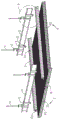
Fig. 1 is a schematic view of the overall structure of embodiment 1 of the present invention.
Fig. 2 is a schematic overall structure diagram of another viewing angle according to embodiment 1 of the present invention.
Fig. 3 is an exploded view of example 1 of the present invention.
Fig. 4 is an enlarged view of a portion a in fig. 3.
Fig. 5 is an enlarged view at B in fig. 3.
Fig. 6 is a cross-sectional view of a hanging piece structure according to embodiment 1 of the present invention.
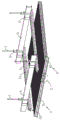
Fig. 7 is an overall mechanism diagram of embodiment 2 of the present invention.
Fig. 8 is an exploded view of embodiment 2 of the present invention.
Fig. 9 is an enlarged view at C in fig. 8.
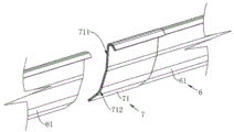
Fig. 10 is a cross-sectional view of a hanging piece structure according to embodiment 2 of the present invention.
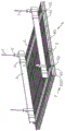
Fig. 11 is an exploded view of embodiment 3 of the present invention.
Fig. 12 is an enlarged view at D in fig. 11.
Fig. 13 is a schematic structural view of a hanging piece module according to embodiment 3 of the present invention.
Fig. 14 is an enlarged view at E in fig. 13.
In the figure: 1. a boom; 2. a clamping piece; 3. a main keel; 4. mounting a sheet; 41. a chute; 5. a false keel; 51. mounting grooves; 52. an opening; 6. hanging a piece; 61. a hanging piece module; 611. a groove; 612. a connecting rod; 613. connecting grooves; 614. a rubber block; 7. a connecting member; 71. connecting sheets; 711. a slot; 712. anti-skid bumps; 72. splicing sheets; 721. and (4) a bump.
Detailed Description
The present invention will be described in further detail with reference to the following drawings and specific embodiments. In the present specification, the terms "upper", "inner", "middle", "left", "right" and "one" are used for convenience of description, and are not intended to limit the scope of the present invention, and the relative relationship between the terms and the corresponding parts may be changed or adjusted without substantial technical changes.
Example 1:
referring to fig. 1 to 4 show a curtain hanging piece mounting structure that hangs down, including a plurality of jib 1 of installing on the roof through the inflation screw, a plurality of jibs 1 are the array and arrange, and jib 1 is kept away from the one end on roof and is attached to be connected with and press from both sides tight piece 2 through the screw lock, and the one end that presss from both sides tight piece 2 and keep away from jib 1 is buckled and is set up, and the kink of pressing from both sides tight piece 2 is pegged graft and is had main joist 3, and the both ends of pressing from both sides tight piece 2 are attached to be. Main joist 3 sliding fit has a plurality of installation pieces 4, and installation piece 4 is made through aluminium system material, and installation piece 4 sets up the outer peripheral face setting of wrapping up in its length direction of main joist 3 perpendicular to through buckling, and the one end of installation piece 4 and the outer peripheral face butt of main joist 3, the one end orientation that main joist 3 was kept away from to installation piece 4 set up the one side of keeping away from the roof, and the protrusion sets up in the bottom surface of keeping away from the roof of main joist 3.
Specifically, the hanging curtain hanging piece 6 ceiling is integrally hung on the roof by arranging the hanging rods 1, the hanging rods 1 are arranged in an array mode, the hanging curtain hanging piece 6 ceiling needle bodies are uniformly distributed on the roof, the clamping pieces 2 are arranged at one ends of the hanging rods 1, the main keel 3 is installed in a bending mode in an inserting mode, the installation mode of the main keel 3 is simple and convenient, and the main keel 3 is clamped in a screw and nut locking and attaching connection mode so as to be convenient to install and fix the main keel 3; through setting up installation piece 4, installation piece 4 is installed the parcel in the periphery of main joist 3 through the mode of buckling, makes installation and the fixed simple and convenient of installation piece 4.
Referring to fig. 3 to 5, a sliding groove 41 is penetrated through a side surface of one end of the mounting piece 4 protruding out of the bottom surface of the main keel 3, the sliding groove 41 extends along one side perpendicular to the length direction of the main keel 3, the cross section of the sliding groove 41 is arranged in a similar inverted triangle shape, the mutually opposite mounting and inserting fit of the adjacent main keels 3 is provided with the auxiliary keel 5, the length direction of the auxiliary keel 5 is perpendicular to the length direction of the main keel 3, the cross section of the auxiliary keel 5 perpendicular to the length direction is arranged in a similar inverted triangle shape, an opening 52 is formed in the bottom surface of the auxiliary keel 5 far away from the mounting piece 4, the opening 52 extends along the length direction of the auxiliary keel 5, and an included angle between two side surfaces perpendicular to the length direction of the auxiliary keel 5 is arranged in a one hundred twenty.
Referring to fig. 1 to 5, a plurality of mounting grooves 51 communicated with an opening 52 are formed in the side face of the auxiliary keel 5 perpendicular to the length direction of the auxiliary keel, the mounting grooves 51 are in hooked arrangement, the mounting grooves 51 are distributed at equal intervals along the length direction of the auxiliary keel 5, hanging pieces 6 are matched with the mounting grooves 51 of the auxiliary keel 5 in an inserting manner, each hanging piece 6 comprises a plurality of hanging piece modules 61 connected with each other in a pairwise manner, one ends of the sliding piece modules are in hooked arrangement and matched with the mounting grooves 51 in an inserting manner, the other ends of the sliding piece modules are arranged downwards in an inclined manner towards one side far away from the hooked end of each sliding piece module, and a connecting piece.
Specifically, through setting up spout 41 that is "inverted triangle" type setting on installation piece 4, utilize triangular stable structure to keep away from, make false keel 5 installation stable, be favorable to reducing the condition of false keel 5 and installation piece 4 alternate segregation. Because the cross section of the false keel 5 is arranged in a triangular shape, and the opening 52 is arranged on the bottom surface of the false keel 5 far away from the installation sheet 4, and an included angle of 120 degrees is formed between two side surfaces of the false keel 5 perpendicular to the length direction of the false keel, according to the principle of a triangular stable structure, because the installation groove 51 is just matched with the installation hanging sheet module 61, the triangular structure is favorable for reducing the gravity effect on the false keel 5 due to the hanging sheet 6, reducing the condition that the two side surfaces of the ancient keel are bent and deformed towards the middle position at the same time, and is favorable for improving the stability of the whole structure of the false keel 5; meanwhile, the position between two contact points of the auxiliary keel 5 and the hanging piece module 61 forms an installation supporting structure of the hanging piece module 61, so that the effect of increasing the supporting and installing space of the hanging piece module 61 is achieved, and the stability of installing the hanging piece module 61 is improved.
Referring to fig. 3 to 6, the connecting member 7 includes a connecting sheet 71, the shape of the cross section of the connecting sheet 71 is consistent with the shape of the cross section of the hanging sheet module 61, slots 711 for the hanging sheet module 61 to be inserted and matched are respectively formed at two ends of the connecting sheet 71 along the length direction, and a plurality of anti-slip bumps 712 are arranged on the inner wall of the slot 711 to enhance the matching friction force.
Specifically, through set up connecting piece 7 between adjacent lacing film module 61 to connect and form the longer lacing film 6 of length, divide into a plurality of lacing film module 61 unit and a plurality of connecting piece 7 with lacing film 6 through the modular form, make lacing film module 61 and connecting piece 7 homoenergetic realize modularization and unitized production, be convenient for carry out batch production, reduce the size of production apparatus and mould simultaneously, and then reduce the production space, in order to improve production efficiency and practice thrift manufacturing cost's effect.
Meanwhile, by arranging the connecting sheet 71 and the slot 711 on the connecting sheet 71, the hanging sheet module 61 is inserted into the slot 711 on the connecting sheet 71 in a pulling and inserting mode, so that a hanging sheet 6 with a longer length is formed, and the connecting and mounting operation of the hanging sheet module 61 and the connecting sheet 71 is simple and convenient; the anti-skidding bumps 712 are arranged on the inner wall of the slot 711, so that the friction force on the surface of the inner wall of the slot 711 is enhanced, the situation that the hanging piece module 61 is separated from the slot 711 of the connecting piece 71 is reduced, and the mounting stability between the connecting piece 71 and the hanging piece module 61 is improved. Therefore, when the electrical equipment and the pipeline arrangement facilities on the ceiling of the drapery hanging piece 6 need to be maintained, the hanging piece module 61 can be pulled out from the slot 711 of the adjacent connecting piece 71 according to the required maintenance designated position, so that the hanging piece modules 61 with the corresponding number can be disassembled, the existing mode of disassembling the drapery hanging piece 6 integrally is favorably reduced, the disassembling operation of the hanging piece module 61 is simple and convenient, and the effect of facilitating the maintenance of the electrical equipment and the pipeline arrangement facilities at the top of the drapery hanging piece 6 is achieved.
When the electrical equipment or the pipeline arrangement facility on the ceiling of the hanging curtain hanging piece 6 needs to be maintained, a position needing to be maintained is found and a space which can be approximately maintained at the position is planned, and because the hanging piece 6 has a distance between two ends along the length direction of the hanging piece and the wall, the hanging piece module 61 opposite to the space can be pulled out of the slot 711 of the connecting piece 71 so as to disassemble the hanging piece module 61 and the connecting piece 71 to form a corresponding maintenance space, and a maintenance worker can perform maintenance operation through the disassembled space; after the maintenance is finished, the hanging piece module 61 is matched with the slot 711 of the connecting piece 71 in an inserting mode, and then the initial state of the hanging curtain hanging piece 6 ceiling is formed.
Example 2:
example 2 differs from example 1 in that:
referring to fig. 7 to 10, the connecting member 7 includes a splicing piece 72, a cross section of the splicing piece 72 has a shape identical to that of the cross section of the hanging piece module 61, two end faces of the splicing piece 72 along a length direction thereof are both fixedly connected with three protrusions 721, the protrusions 721 are arranged in a cylindrical shape, and the three protrusions 721 are respectively distributed at two ends and a middle position along the cross section of the splicing piece 72. The two end faces of the hanging piece module 61 along the length direction are respectively provided with three grooves 611 which are opposite to the three protrusions 721 of the splicing piece 72, and the grooves 611 of the hanging piece module 61 are used for the insertion and matching of the protrusions 721 of the splicing piece 72. When the projection 721 of the splicing piece 72 is spliced and fitted with the hanging piece module 61, the outer peripheral surface of the splicing piece 72 perpendicular to the length direction thereof is arranged coplanar with the outer peripheral surface of the hanging piece module 61 perpendicular to the length direction thereof.
Specifically, the splicing sheet 72 and the projection 721 on the splicing sheet 72 are arranged, so that the projection 721 is conveniently in inserted fit with the groove 611 of the hanging sheet module 61, and the hanging sheet 6 with a longer length is formed by a pulling and inserting mode, so that the mounting and dismounting operations of the hanging sheet 6 are simple and convenient; when electrical equipment and pipeline arrangement facilities on the 6 smallpox of curtain lacing film that hangs down need be maintained, assigned position that can maintain as required, with the recess 611 of lacing film module 61 and the lug 721 alternate segregation of adjacent concatenation piece 72, with lacing film module 61 and the concatenation piece 72 of dismantling and taking out, thereby form the maintenance space of corresponding size, the maintenance personal of being convenient for sees through this space and maintains, make the dismantlement of lacing film module 61 easy and simple to handle, and then reach the effect that the electrical equipment and the pipeline arrangement facilities at the curtain lacing film 6 top of being convenient for maintain.
When the electrical equipment or the pipeline arrangement facility on the ceiling of the hanging curtain hanging piece 6 needs to be maintained, a position needing to be maintained is found and a space which can be approximately maintained at the position is planned, and as the hanging piece 6 has a distance between two ends along the length direction of the hanging piece and the wall, the lug 721 of the splicing piece 72 opposite to the space can be pulled out from the groove 611 of the hanging piece module 61 so as to disassemble the hanging piece module 61 and the connecting piece 71 to form a corresponding maintenance space, and a maintenance worker can perform maintenance operation through the disassembled space; after the maintenance is finished, the groove 611 of the hanging piece module 61 is matched with the projection 721 of the splicing piece 72 in an inserting way, and then the initial state of the hanging curtain hanging piece 6 ceiling is formed.
Example 3:
example 3 differs from example 1 in that:
referring to fig. 11 to 14, the connecting member 7 includes two connecting rods 612 integrally connected to a side surface of one end of the hanging piece module 61 along the length direction, the two connecting rods 612 are distributed at two ends of the cross section of the hanging piece module 61 along the length direction, one end of the hanging piece module 61 away from the connecting rods 612 is provided with two connecting grooves 613 opposite to the two connecting rods 612 of the hanging piece module 61, the cross section of the connecting groove 613 is circular, and the connecting grooves 613 are used for the connecting rods 612 to be inserted and matched. One end of the connecting rod 612 far away from the hanging piece module 61 is fixedly connected with a rubber block 614, and the diameter of the outer peripheral surface of the rubber block 614 is larger than the diameter of the inner wall of the connecting groove 613.
Specifically, a connecting rod 612 is arranged at one end of each hanging piece module 61, a connecting groove 613 for the connecting rod 612 to be inserted and matched is arranged at the other end of each hanging piece module 61, and the connecting rods 612 of the hanging piece modules 61 are inserted and connected with the connecting groove 613 of the other hanging piece module 61, so that the hanging pieces 6 with longer length are formed by the plurality of hanging piece modules 61 in a mutual splicing and pulling manner, and the mounting and dismounting operations of the hanging pieces 6 are simple and convenient; when electrical equipment and pipeline arrangement facilities on the 6 smallpox of curtain lacing film that hangs down need be maintained, the assigned position that can maintain as required, with the connecting rod 612 of lacing film module 61 and the spread groove 613 alternate segregation of adjacent lacing film module 61, with the lacing film module 61 of dismantling and taking out, thereby form the maintenance space of corresponding size, the maintenance personal of being convenient for sees through this space and maintains, make the dismantlement of lacing film module 61 easy and simple to handle, and then reach the effect that the electrical equipment and the pipeline arrangement facilities at the curtain lacing film 6 top of being convenient for maintain.
Meanwhile, by arranging the rubber block 614 and utilizing the interference fit between the rubber block 614 and the connecting groove 613, the situation that the connecting rod 612 and the connecting groove 613 are separated from each other is reduced, and the stability of the mutual connection and matching between the connecting rod 612 and the connecting groove 613 is enhanced.
When the electrical equipment or the pipeline arrangement facility on the top of the ceiling of the hanging curtain hanging piece 6 needs to be maintained, a position needing to be maintained is found and a space which can be approximately maintained at the planned position is planned, and because the hanging piece 6 has a distance between two ends along the length direction of the hanging piece 6 and the wall, the connecting rod 612 of the hanging piece module 61 opposite to the space can be pulled out from the connecting groove 613 of the adjacent hanging piece 6 module so as to disassemble a plurality of hanging piece 6 modules which are connected with each other and form a corresponding maintenance space, and maintenance personnel can perform maintenance operation through the disassembled space; after the maintenance is finished, the adjacent hanging piece modules 61 are in insertion fit, and then the initial state of the hanging curtain hanging piece 6 ceiling is formed.
In conclusion, by arranging the suspender 1 and the main keel 3, connecting the suspender 1 with a roof, and connecting the hanging piece 6 with the main keel 3, the ceiling of the hanging curtain hanging piece 6 is hung on the roof, by arranging the installation piece 4 on the main keel 3 to connect and install the auxiliary keel 5, by arranging the plurality of installation grooves 51 on the auxiliary keel 5, the hanging piece 6 is connected and installed, so that the integral structure of the ceiling of the hanging curtain hanging piece 6 is formed, by arranging the plurality of hanging piece modules 61 which are spliced with each other in pairs, the integral structure of the hanging piece 6 is formed, and by carrying out module and unitization on the hanging piece 6, the sizes of a production mold and production equipment for producing the hanging piece 6 are favorably reduced, so that the effect of reducing the production space is achieved, the mass production is facilitated, the production cost is saved, and the carrying and transportation space is favorably reduced;
meanwhile, the connecting piece 7 is arranged between the adjacent hanging piece modules 61, so that the adjacent hanging piece modules 61 can be spliced and installed conveniently; when electrical equipment and the pipeline facility of arranging of 6 smallpox tops of curtain lacing film that hangs down need be maintained, the assigned position that can maintain as required, with connecting piece 7 and adjacent lacing film module 61 separation, lacing film module 61 of dismantling and taking out, thereby form the maintenance space of corresponding size, the maintenance personal of being convenient for sees through this space and maintains, reduce the operation mode of wholly dismantling lacing film 6, make the dismantlement of lacing film module 61 easy and simple to handle, and then reach the electrical equipment and the pipeline facility's of arranging effect of being convenient for maintain curtain lacing film 6 top.
The embodiment of the present invention is not limited to this, according to the above-mentioned content of the present invention, the common technical knowledge and the conventional means in the field are utilized, without departing from the basic technical idea of the present invention, the present invention can also make other modifications, replacements or combinations in various forms, all falling within the protection scope of the present invention.
Claims (8)
1. The utility model provides a curtain lacing film mounting structure hangs down which characterized by: including the jib, the jib is connected with the main joist, the main joist is connected with the installation piece, the installation piece is pegged graft and is had the false keel, a plurality of mounting grooves have been seted up along its length direction to the false keel, the mounting groove is pegged graft and is had the lacing film, the lacing film includes the lacing film module of a plurality of two liang of mutual concatenations, and is adjacent be provided with the connecting piece between the lacing film module.
2. The drapery tab mounting structure of claim 1, wherein: the connecting piece comprises a connecting piece, and the connecting piece is provided with a plurality of slots for the insertion and matching of the hanging piece modules.
3. The drapery tab mounting structure of claim 2, wherein: the inner wall of the slot is provided with a plurality of anti-skidding convex points.
4. The drapery tab mounting structure of claim 1, wherein: the hanging piece module is provided with grooves at two ends along the length direction, the connecting piece comprises splicing pieces, and a plurality of convex blocks which are matched with the grooves in an inserted manner are protruded on the splicing pieces.
5. The drapery tab mounting structure of claim 4, wherein: when the splicing sheet is connected and matched with the hanging sheet module, the peripheral surface of the splicing sheet and the peripheral surface of the hanging sheet module are arranged in a coplanar manner.
6. The drapery tab mounting structure of claim 1, wherein: the connecting piece including set up in the connecting rod of lacing film module one end, the lacing film module is kept away from the spread groove that supplies the connecting rod grafting adaptation is seted up to the one end of connecting rod.
7. The drapery tab mounting structure of claim 1, wherein: the mounting piece is provided with a sliding groove for the insertion sliding of the auxiliary keel, and the cross section of the sliding groove is shaped like an inverted triangle.
8. The drapery tab mounting structure of claim 7, wherein: the cross section of false keel perpendicular to its length direction is like "triangle", false keel keeps away from the opening has been seted up to the one end of installation piece, the mounting groove with the opening communicates each other.
Priority Applications (1)
| Application Number | Priority Date | Filing Date | Title |
|---|---|---|---|
| CN202020612871.XU CN212200967U (en) | 2020-04-22 | 2020-04-22 | Hanging curtain hanging sheet mounting structure |
Applications Claiming Priority (1)
| Application Number | Priority Date | Filing Date | Title |
|---|---|---|---|
| CN202020612871.XU CN212200967U (en) | 2020-04-22 | 2020-04-22 | Hanging curtain hanging sheet mounting structure |
Publications (1)
| Publication Number | Publication Date |
|---|---|
| CN212200967U true CN212200967U (en) | 2020-12-22 |
Family
ID=73827694
Family Applications (1)
| Application Number | Title | Priority Date | Filing Date |
|---|---|---|---|
| CN202020612871.XU Active CN212200967U (en) | 2020-04-22 | 2020-04-22 | Hanging curtain hanging sheet mounting structure |
Country Status (1)
| Country | Link |
|---|---|
| CN (1) | CN212200967U (en) |
-
2020
- 2020-04-22 CN CN202020612871.XU patent/CN212200967U/en active Active
Similar Documents
| Publication | Publication Date | Title |
|---|---|---|
| CN101832525A (en) | Spliced lamp shell | |
| CN113356448A (en) | Installation device and installation method of curved surface metal ceiling | |
| CN113718985A (en) | Assembled partition wall structure convenient to disassemble and assemble and installation method | |
| CN201411783Y (en) | Box type combined house with convenient disassembly and assembly | |
| CN111021609B (en) | Inclined plane unit type curtain wall | |
| CN113668756B (en) | Large-span aluminum square tube multiple-drop-level modeling assembly type installation design structure | |
| CN214220202U (en) | An aluminum gusset structure | |
| CN113756513B (en) | Assembled ceiling facing and installation method | |
| CN213810280U (en) | Track line type lamp mounting structure | |
| CN215519406U (en) | Suspension type cell body curtain aluminium alloy | |
| CN210369505U (en) | Arc-shaped lamp groove ceiling module | |
| CN220620660U (en) | Assembled furred ceiling | |
| CN215888812U (en) | Installation device of curved surface metal furred ceiling | |
| CN101775866B (en) | Suspended ceiling | |
| CN216405861U (en) | Hang stone material curtain connected system futilely | |
| CN216130380U (en) | Assembled partition wall structure convenient to dismouting | |
| CN211873500U (en) | Large-span suspended ceiling with suspended ribbon shape | |
| CN205722642U (en) | LED display curtain | |
| CN221881273U (en) | LED lamp conversion frame convenient to dismantle | |
| CN218843506U (en) | Back increase closed ceiling system of finished product aluminium square tube structure | |
| CN213810346U (en) | A flying saucer light that is easy to disassemble and repair | |
| CN220814509U (en) | Suspended ceiling installation fixing device | |
| CN217896962U (en) | Suspended ceiling of assembled fitment | |
| CN206890308U (en) | Hyperboloid light fixture decorative panel | |
| CN207196059U (en) | The lamp box profile structure of two-sided card cloth |
Legal Events
| Date | Code | Title | Description |
|---|---|---|---|
| GR01 | Patent grant | ||
| GR01 | Patent grant |