CN212198259U - Tower Crane Attachment Device - Google Patents
Tower Crane Attachment Device Download PDFInfo
- Publication number
- CN212198259U CN212198259U CN202020513305.3U CN202020513305U CN212198259U CN 212198259 U CN212198259 U CN 212198259U CN 202020513305 U CN202020513305 U CN 202020513305U CN 212198259 U CN212198259 U CN 212198259U
- Authority
- CN
- China
- Prior art keywords
- connecting rod
- tower crane
- main building
- fixedly connected
- hoop
- Prior art date
- Legal status (The legal status is an assumption and is not a legal conclusion. Google has not performed a legal analysis and makes no representation as to the accuracy of the status listed.)
- Expired - Fee Related
Links
Images


Landscapes
- Jib Cranes (AREA)
Description
技术领域technical field
本实用新型涉及一种塔吊附着装置。The utility model relates to a tower crane attachment device.
背景技术Background technique
塔吊是建筑工地上最常用的一种起重设备,用来吊施工用的钢筋、木楞、混凝土、钢管等施工的原材料。现有技术中,塔吊通过多组塔吊附着装置与主体固定,每组塔吊附着装置的附着架与三个拉杆配合实现与主体建筑连接固定,附着架设置固定高程的两个标准节臂之间,拉杆一端通过螺栓与附着架固定,拉杆另一端通过预埋的螺栓与主体建筑连接固定,但现有拉杆的数量为三根,塔吊的稳定性欠缺,另外,在主体建筑表面预埋螺栓,后续主体建筑完工后,会造成预埋位置漏水等质量问题。Tower cranes are the most commonly used lifting equipment on construction sites, and are used to hoist construction materials such as steel bars, corrugated wood, concrete, and steel pipes. In the prior art, the tower crane is fixed to the main body through multiple sets of tower crane attachment devices. The attachment frame of each group of tower crane attachment devices cooperates with three tie rods to achieve connection and fixation with the main building. One end of the tie rod is fixed with the attachment frame by bolts, and the other end of the tie rod is connected and fixed with the main building through the embedded bolts, but the existing number of tie rods is three, and the stability of the tower crane is lacking. After the construction is completed, it will cause quality problems such as water leakage in the pre-embedded location.
实用新型内容Utility model content
本实用新型所要解决的技术问题是提供一种结构稳固、可灵活拆卸的塔吊附着装置。The technical problem to be solved by the utility model is to provide a tower crane attachment device with stable structure and flexible disassembly.
为解决上述技术问题,本实用新型提供了一种塔吊附着装置,包括标准节附着架,标准节附着架固定在塔吊的两节标准节臂之间;In order to solve the above technical problems, the utility model provides a tower crane attachment device, comprising a standard section attachment frame, and the standard section attachment frame is fixed between two standard section arms of the tower crane;
包括四根连杆和两组抱箍组件;Including four connecting rods and two sets of hoop assemblies;
两组抱箍组件分别与主体建筑靠近塔吊节臂一侧的两个混凝土柱配合, 所述抱箍组件包括两个抱板和若干固定螺栓,两个抱板分别紧贴主体建筑的混凝土柱两侧,两个抱板之间通过若干固定螺栓连接固定,两组抱箍组件的水平高度一致;The two sets of hoop assemblies are respectively matched with the two concrete columns on the side of the main building close to the tower crane section arm. The two holding plates are connected and fixed by several fixing bolts, and the horizontal heights of the two groups of holding hoop components are the same;
四根连杆分别是第一连杆、第二连杆、第三连杆和第四连杆,第一连杆和第二连杆与一组抱箍组件对应,第三连杆和第四连杆与另一组抱箍组件对应,第一连杆一端与靠近主体建筑一侧的标准节附着架近角位置固定连接,第一连杆另一端与对应的抱箍组件固定连接,第二连杆一端与靠近主体建筑一侧的标准节附着架远角位置固定连接,第二连杆另一端与对应的抱箍组件固定连接,第三连杆一端与标准节附着架旁侧侧壁的近角位置固定连接,第三连杆另一端与对应的抱箍组件固定连接,第四连杆一端与标准节附着架旁侧侧壁的远角位置固定连接,第四连杆另一端与对应的抱箍组件固定连接。The four connecting rods are the first connecting rod, the second connecting rod, the third connecting rod and the fourth connecting rod respectively. The first connecting rod and the second connecting rod correspond to a set of hoop assemblies, and the third connecting rod and the fourth connecting rod The connecting rod corresponds to another group of hoop assemblies, one end of the first connecting rod is fixedly connected to the near-angle position of the standard section attachment frame close to the side of the main building, the other end of the first connecting rod is fixedly connected to the corresponding hoop assembly, and the second connecting rod is fixedly connected to the corresponding hoop assembly. One end of the rod is fixedly connected to the far corner of the standard section attachment frame close to the main building, the other end of the second link is fixedly connected to the corresponding hoop assembly, and one end of the third link is fixed to the near angle of the side wall of the standard section attachment frame. The position is fixedly connected, the other end of the third connecting rod is fixedly connected with the corresponding hoop assembly, one end of the fourth connecting rod is fixedly connected with the far-angle position of the side wall of the standard section attachment frame, and the other end of the fourth connecting rod is fixedly connected with the corresponding holding hoop. The hoop assembly is fixedly connected.
采用这样的结构后,通过两组抱箍组件与主体建筑的混凝土柱配合,实现塔吊与主体建筑物之间的连接固定,后续主体建筑完工后,只需拆除抱箍组件即可以去除塔吊与主体建筑物之间的连接,不会对主体建筑表面造成损伤,避免后续发生漏水问题;After adopting such a structure, two sets of hoop assemblies cooperate with the concrete columns of the main building to realize the connection and fixation between the tower crane and the main building. After the subsequent main building is completed, the tower crane and the main body can be removed by removing the hoop assemblies. The connection between buildings will not cause damage to the surface of the main building and avoid subsequent water leakage problems;
另外,四根连杆的固定结构和彼此的分布位置强化了附着架与主体建筑之间连接的稳定性,比现有三根连杆的连接结构更能提高塔吊与主体建筑固定的安全性。In addition, the fixed structure of the four connecting rods and the distribution positions of each other strengthen the stability of the connection between the attachment frame and the main building, which can improve the safety of fixing the tower crane to the main building more than the existing three connecting rod connection structure.
为了更清楚的理解本实用新型的技术内容,以下将本塔吊附着装置简称为本附着装置。In order to understand the technical content of the present invention more clearly, the tower crane attachment device is hereinafter referred to as the attachment device.
本附着装置的四根连杆结构相同,所述连杆包括第一耳板、第一螺纹套管、第二螺纹套管、第二耳板和双头螺杆,第一耳板固定连接在第一螺纹套管上,第二耳板固定连接在第二螺纹套管上,第一螺纹套管和第二螺纹套管分别与双头螺杆配合;采用这样的结构后,可以调节双头螺杆伸入第一螺纹套管或第二螺纹套管的长度,达到对连杆长度进行灵活微调的目的,方便本附着装置的装配作业。The four connecting rods of the attachment device have the same structure. The connecting rods include a first lug plate, a first threaded sleeve, a second threaded sleeve, a second lug plate and a double-ended screw. The first lug plate is fixedly connected to the first lug plate. On a threaded sleeve, the second lug plate is fixedly connected to the second threaded sleeve, and the first threaded sleeve and the second threaded sleeve are respectively matched with the double-ended screw; after adopting this structure, the extension of the double-ended screw can be adjusted. The length of the first threaded sleeve or the second threaded sleeve can be adjusted to achieve the purpose of flexibly fine-tuning the length of the connecting rod and facilitate the assembly operation of the attachment device.
本附着装置的第一连杆与靠近塔吊节臂一侧的主体建筑侧面之间具有 82~86°;第二连杆与靠近塔吊节臂一侧的主体建筑侧面之间具有60~65°;第三连杆与靠近塔吊节臂一侧的主体建筑侧面之间具有40~45°;第四连杆与靠近塔吊节臂一侧的主体建筑侧面之间具有52~56°;采用这样的结构后,四根连杆的布置位置及角度参数更具体,进一步提升本附着装置的稳固性。The angle between the first link of the attachment device and the side of the main building near the side of the tower crane section arm is 82-86°; the distance between the second link and the side of the main building on the side of the tower crane section arm is 60-65°; The distance between the third link and the side of the main building near the arm of the tower crane is 40 to 45°; the distance between the fourth link and the side of the main building near the arm of the tower crane is 52 to 56°; adopt such a structure After that, the arrangement position and angle parameters of the four connecting rods are more specific, which further improves the stability of the attachment device.
附图说明Description of drawings
图1是本附着装置实施例的俯视图。Figure 1 is a top view of an embodiment of the attachment device.
图2是本附着装置实施例连杆的结构示意图。FIG. 2 is a schematic structural diagram of a connecting rod according to an embodiment of the attachment device.
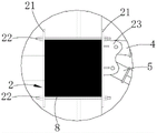
图3是图1的A部放大图。FIG. 3 is an enlarged view of part A of FIG. 1 .
具体实施方式Detailed ways
如图1至3所示As shown in Figures 1 to 3
本附着装置包括标准节附着架1、四根连杆和两组抱箍组件。The attachment device includes a standard
标准节附着架1采用市售的标准节附着架1,标准节附着架1固定在塔吊的两节标准节臂之间。The standard
两组抱箍组件分别为第一抱箍组件2和第二抱箍组件3,第一抱箍组件2 和第二抱箍组件3的结构相同,以第一抱箍组件2为例具体介绍抱箍组件的结构,第一抱箍组件2包括两个抱板21和六个固定螺栓22,两个抱板21分别紧贴主体建筑的混凝土柱8两侧,两个抱板21之间通过六个固定螺栓22 连接固定,其中一个抱板21上焊接有第三耳板23;The two groups of hoop assemblies are respectively the
第一抱箍组件2和第二抱箍组件3分别与主体建筑靠近塔吊节臂一侧的两个混凝土柱8配合,第一抱箍组件2和第二抱箍组件3分别左右布置,第一抱箍组件2和第二抱箍组件3的水平高度一致。The
四根连杆结构相同,四根连杆分别是第一连杆4、第二连杆5、第三连杆 6和第四连杆7,以第一连杆4为例,第一连杆4包括第一耳板41、第一螺纹套管42、第二螺纹套管43、第二耳板44和双头螺杆45,第一螺纹套管42和第二螺纹套管43为方管结构,第一螺纹套管42、第二螺纹套管43内孔壁设有螺纹,第一耳板41焊接在第一螺纹套管42上,第二耳板44焊接在第二螺纹套管43上,第一螺纹套管42和第二螺纹套管43分别与双头螺杆45配合。The four connecting rods have the same structure. The four connecting rods are the first connecting
第一连杆4和第二连杆5与第一抱箍组件2对应,第三连杆6和第四连杆7与第二抱箍组件3对应,第一连杆4一端与靠近主体建筑一侧标准节附着架1近角位置的耳板通过螺栓固定,第一连杆4另一端与第一抱箍组件2 的第三耳板23通过螺栓固定,第二连杆5一端与靠近主体建筑一侧标准节附着架1远角位置的耳板通过螺栓固定,第二连杆5另一端与第一抱箍组件2 的第三耳板23通过螺栓固定,第三连杆6一端与标准节附着架1旁侧侧壁近角位置的耳板通过螺栓固定,第三连杆6另一端与第二抱箍组件3通过螺栓固定,第四连杆7一端与标准节附着架1旁侧侧壁远角位置的耳板通过螺栓固定,第四连杆7另一端与第二抱箍组件3通过螺栓固定。The first connecting
第一连杆4与靠近塔吊节臂一侧的主体建筑侧面之间倾角α为84°;第二连杆5与靠近塔吊节臂一侧的主体建筑侧面之间倾角β为63°;第三连杆 6与靠近塔吊节臂一侧的主体建筑侧面之间倾角γ为41°;第四连杆7与靠近塔吊节臂一侧的主体建筑侧面之间倾角δ为54°。The inclination angle α between the first connecting
本实施例的附墙受力计算,如下:The force calculation of the attached wall in this embodiment is as follows:
a)参数信息;a) parameter information;
塔吊高度98.80(m),附着塔吊边长:2.00(m),附着塔吊最大倾覆力矩:4981.60(kN/m),附着框宽度:2.40(m),回转扭矩:300.00(kN/m),风荷载设计值:0.5(kN/m),各层附着高度分别:42.1、63.1(m)。Tower crane height 98.80(m), attached tower crane side length: 2.00(m), attached tower crane maximum overturning moment: 4981.60(kN/m), attached frame width: 2.40(m), slewing torque: 300.00(kN/m), wind Design value of load: 0.5 (kN/m), attachment height of each layer: 42.1, 63.1 (m).
b)支座力计算;b) Calculation of bearing force;
塔机按照说明书与建筑物附着时,最上面一道附着装置的负荷最大,因此以此道连杆的负荷作为设计或校核附着杆截面的依据。When the tower crane is attached to the building according to the instructions, the uppermost attachment device has the largest load, so the load of this connecting rod is used as the basis for designing or checking the section of the attachment rod.
附着式塔机的塔身可以视为一个带悬臂的刚性支撑连续梁,其内力及支座反力计算如下:The tower body of the attached tower crane can be regarded as a rigid support continuous beam with cantilever, and its internal force and support reaction force are calculated as follows:
其中:in:
W0──基本风压(kN/m2),按照《建筑结构荷载规范》(GBJ9)的规定采用:W0=0.4kN/m2;W 0 ──Basic wind pressure (kN/m2), adopted in accordance with the “Code for Loads of Building Structures” (GBJ9): W 0 =0.4kN/m2;
μz──风荷载高度变化系数,按照《建筑结构荷载规范》(GBJ9)的规定采用:μz=2.380;μ z — wind load height variation coefficient, adopted in accordance with the provisions of "Code for Loads of Building Structures" (GBJ9): μ z = 2.380;
μs──风荷载体型系数:μs=2.600;μ s ── wind load body shape coefficient: μ s = 2.600;
βz──风振系数,依据《建筑结构荷载规范》结构在Z高度处的风振系数按公式规定,计算βz=1.1;β z ─ wind vibration coefficient, according to the wind vibration coefficient of the structure at the Z height according to the "Code for Loads of Building Structures", calculate β z = 1.1;
Wk──风荷载水平压力;W k —— wind load horizontal pressure;
Wk=W0×μz×μs×βz=0.4×2.38×2.6×1.1=2.72kN/m2;B──塔吊作用宽度,B=2.00m;Ks──迎风面积折减系数,Ks=0.20;W k =W 0 ×μ z ×μ s ×β z =0.4×2.38×2.6×1.1=2.72kN/m 2 ; B——the working width of the tower crane, B=2.00m; K s ——the reduction factor of the windward area , K s =0.20;
经计算得到风荷载的水平作用力;风荷载实际取值q=0.5kN/m,塔吊的最大倾覆力矩M=4981.60kN.m,计算结果:Nw=260.379kN。The horizontal force of the wind load is obtained by calculation; the actual value of the wind load is q=0.5kN/m, the maximum overturning moment of the tower crane is M=4981.60kN.m, and the calculation result: Nw=260.379kN.
c)附着杆内力计算c) Calculation of the internal force of the attachment rod
以上的计算过程将θ从0-360度循环,解得每连杆的最大轴压力,最大轴拉力:The above calculation process will cycle θ from 0-360 degrees to solve the maximum axial pressure and maximum axial tension of each connecting rod:
第三连杆6的最大轴向拉力为:221.5kN;第三连杆6的最大轴向压力为: 221.5kN;The maximum axial tension of the third connecting
第四连杆7的最大轴向拉力为:273.0kN;第四连杆7的最大轴向压力为: 273.0kN;The maximum axial tension of the fourth connecting rod 7 is: 273.0kN; the maximum axial pressure of the fourth connecting rod 7 is: 273.0kN;
第一连杆4的最大轴向拉力为:416.0kN;第一连杆4的最大轴向压力为: 416.0kN;The maximum axial tension of the first connecting
第二连杆5的的最大轴向拉力为:353.0kN;第二连杆5的最大轴向压力为:353.0kN。The maximum axial tension of the second connecting
d)附着杆强度验算:d) Checking the strength of the attachment rod:
附着拉杆采用200×200×6方管,截面尺寸是200×200×6;The attached tie rod adopts 200×200×6 square tube, and the section size is 200×200×6;
连杆截面特性如下:The cross-sectional properties of the connecting rod are as follows:
A=46.56cm2,Ix=2923.35cm4;A=46.56cm 2 , Ix =2923.35cm 4 ;

单位重量:36.55Kg/m。Unit weight: 36.55Kg/m.
1)受力分析:1) Force analysis:
a.轴拉力、轴压力。a. Shaft tension, shaft pressure.
b.选用拉第一连杆4,长度4.14m,其受力最大,N=416.0KN。b. Select the first connecting
c.风载荷;c. Wind load;
风载荷计算公式——Fw=CwpwA;Wind load calculation formula - F w =C w p w A;
本实施例中l/h=4140/200=20.7,取CW=1.75;In this embodiment, l/h=4140/200=20.7, take C W =1.75;
本实施例取pw=1100Pa;This embodiment takes p w =1100Pa;
垂直迎风面积A=4.14×0.20;Vertical windward area A=4.14×0.20;
FW=CWPWA=1.75×1.1×4.14×0.20=1.59KN;F W =C W P W A=1.75×1.1×4.14×0.20=1.59KN;
该力作用于连杆表现为水平向弯矩:This force acts on the connecting rod as a horizontal bending moment:
M1=FWl/10=0.66KN·m。M 1 =F W l/10=0.66KN·m.
d.连杆自重;d. The weight of the connecting rod;
G=4.14×36.55×9.8=1.48KN该力作用于连杆表现为垂直向弯矩:G=4.14×36.55×9.8=1.48KN This force acts on the connecting rod as a vertical bending moment:
M2=Gl/10=0.613KN·m。M 2 =Gl/10=0.613KN·m.
e.连杆强度校核e. Strength check of connecting rod
按公式

故,连杆强度满足要求。Therefore, the strength of the connecting rod meets the requirements.
2)受压稳定性校核;2) Stability check under pressure;
连杆轴心受压强度验算:验算公式:σ=N/(φ·An)≤[σ];Check calculation of compressive strength of connecting rod axis: check formula: σ=N/(φ·A n )≤[σ];
其中:in:
σ──为连杆的受压应力;σ──is the compressive stress of the connecting rod;
N──为连杆的最大轴向拉力;N—— is the maximum axial tension of the connecting rod;
第四连杆7取N=273.0kN;第一连杆4:取N=416.0kN;The fourth connecting rod 7 takes N=273.0kN; the first connecting rod 4: takes N=416.0kN;
φ──为连杆的受压稳定系数,根据λ的值查表可得到,λ为连杆的长细比;φ──is the compression stability coefficient of the connecting rod, which can be obtained by looking up the table according to the value of λ, where λ is the slenderness ratio of the connecting rod;
长细比计算公式:
第四连杆7长度l=8677mm,计算得:
根据λ查表得稳定系数φ=0.499;According to the λ look-up table, the stability coefficient φ=0.499;
根据计算公式:According to the calculation formula:
σ=N/(φ·An)=273×1000/0.499/4656=117.5Mpa≤[σ]=170MPa;σ=N/(φ·A n )=273×1000/0.499/4656=117.5Mpa≤[σ]=170MPa;
满足要求。fulfil requirements.
第一连杆4长度l=4140mm,计算得:
根据λ查表得稳定系数φ=0.847;According to the λ look-up table, the stability coefficient φ=0.847;
根据计算公式:According to the calculation formula:
σ=N/(φ·An)=416×1000/0.847/4656=105.4Mpa≤[σ]=170MPaσ=N/(φ·A n )=416×1000/0.847/4656=105.4Mpa≤[σ]=170MPa
满足要求。fulfil requirements.
以上所述的仅是本实用新型的一种实施方式,应当指出,对于本领域的普通技术人员来说,在不脱离本实用新型原理的前提下,还可以作出若干变型和改进,这些也应视为属于本实用新型的保护范围。The above is only an embodiment of the present invention. It should be pointed out that for those of ordinary skill in the art, without departing from the principles of the present invention, several modifications and improvements can be made, which should also be It is regarded as belonging to the protection scope of the present invention.
Claims (3)
Priority Applications (1)
| Application Number | Priority Date | Filing Date | Title |
|---|---|---|---|
| CN202020513305.3U CN212198259U (en) | 2020-04-09 | 2020-04-09 | Tower Crane Attachment Device |
Applications Claiming Priority (1)
| Application Number | Priority Date | Filing Date | Title |
|---|---|---|---|
| CN202020513305.3U CN212198259U (en) | 2020-04-09 | 2020-04-09 | Tower Crane Attachment Device |
Publications (1)
| Publication Number | Publication Date |
|---|---|
| CN212198259U true CN212198259U (en) | 2020-12-22 |
Family
ID=73829977
Family Applications (1)
| Application Number | Title | Priority Date | Filing Date |
|---|---|---|---|
| CN202020513305.3U Expired - Fee Related CN212198259U (en) | 2020-04-09 | 2020-04-09 | Tower Crane Attachment Device |
Country Status (1)
| Country | Link |
|---|---|
| CN (1) | CN212198259U (en) |
Cited By (3)
| Publication number | Priority date | Publication date | Assignee | Title |
|---|---|---|---|---|
| CN111362155A (en) * | 2020-04-09 | 2020-07-03 | 中国建筑第五工程局有限公司 | Tower Crane Attachment Device |
| CN116395580A (en) * | 2023-04-27 | 2023-07-07 | 中交一公局集团有限公司 | A tower crane attachment system suitable for box-shaped steel columns and its construction technology |
| CN117228557A (en) * | 2023-10-18 | 2023-12-15 | 中建新疆建工集团第一建筑工程有限公司 | A hoop-type attachment connection device for heavy-duty tower suspension columns in steel structure construction |
-
2020
- 2020-04-09 CN CN202020513305.3U patent/CN212198259U/en not_active Expired - Fee Related
Cited By (3)
| Publication number | Priority date | Publication date | Assignee | Title |
|---|---|---|---|---|
| CN111362155A (en) * | 2020-04-09 | 2020-07-03 | 中国建筑第五工程局有限公司 | Tower Crane Attachment Device |
| CN116395580A (en) * | 2023-04-27 | 2023-07-07 | 中交一公局集团有限公司 | A tower crane attachment system suitable for box-shaped steel columns and its construction technology |
| CN117228557A (en) * | 2023-10-18 | 2023-12-15 | 中建新疆建工集团第一建筑工程有限公司 | A hoop-type attachment connection device for heavy-duty tower suspension columns in steel structure construction |
Similar Documents
| Publication | Publication Date | Title |
|---|---|---|
| CN111362155A (en) | Tower Crane Attachment Device | |
| CN107100187B (en) | Tower crane steel girder erection structure and installation method | |
| CN102079489A (en) | Suspended-rising support system of tower crane | |
| CN101942884B (en) | Roof with approximately quadrate plane and super large space pre-stressed steel grid structure and manufacturing method thereof | |
| CN101503908A (en) | Construction method for spacing suspension cable structural template support platform | |
| CN106351464B (en) | Two dimension prestressing gusset reinforces rectangular section concrete post method without breakage online | |
| Liu et al. | Structural behavior of steel tube and coupler scaffolds with stability strengthening details | |
| CN104310234B (en) | External Suspension Climbing Tower Crane Support System | |
| CN202672353U (en) | Panel constraint type concrete filled steel tube composite column-steel beam joint | |
| CN201671227U (en) | Diagonal Arrangement Cross-shaped Steel SRC Columns with Flanges | |
| CN116425059A (en) | A four-section tower crane attachment frame and its installation method | |
| CN201172902Y (en) | Hinge joint anti-buckling brace | |
| CN206539055U (en) | A kind of house crossbeam reinforcement assembly | |
| CN207177086U (en) | It is a kind of can quick assembling set up truss | |
| CN205397790U (en) | A subassembly that is used for construction elevator to attach wall pull rod overlength | |
| CN211285991U (en) | Large-volume complex-curvature steel structure with Shandan Danhua shape | |
| CN210918292U (en) | Beam column node construction protector | |
| CN116305468B (en) | A method for calculating the bearing capacity of vertical support rods in a combined support system of an external steel frame and an inner straight tube of a water tower | |
| CN204125962U (en) | The king-tower post of single-column Guywire tower and the syndeton on basis | |
| CN114104996A (en) | Assembled concrete high-rise building tower crane energy dissipation damping attaches wall pole device | |
| CN202804054U (en) | Built-in truss based on providing support during process of installing C-shaped plate | |
| CN112482789B (en) | Detachable support frame for hoisting large-span prefabricated part and manufacturing method thereof | |
| CN211973557U (en) | An exposed rigid column foot node | |
| CN210134658U (en) | Special tool for adjusting verticality of large steel column | |
| CN209974169U (en) | Swing arm tower machine beam climbing device |
Legal Events
| Date | Code | Title | Description |
|---|---|---|---|
| GR01 | Patent grant | ||
| GR01 | Patent grant | ||
| CF01 | Termination of patent right due to non-payment of annual fee |
Granted publication date: 20201222 |
|
| CF01 | Termination of patent right due to non-payment of annual fee |