CN212197762U - An anti-blocking type cloth feeding device based on cloth setting machine - Google Patents
An anti-blocking type cloth feeding device based on cloth setting machine Download PDFInfo
- Publication number
- CN212197762U CN212197762U CN202020584975.4U CN202020584975U CN212197762U CN 212197762 U CN212197762 U CN 212197762U CN 202020584975 U CN202020584975 U CN 202020584975U CN 212197762 U CN212197762 U CN 212197762U
- Authority
- CN
- China
- Prior art keywords
- guide
- cloth
- roller
- feeding device
- device based
- Prior art date
- Legal status (The legal status is an assumption and is not a legal conclusion. Google has not performed a legal analysis and makes no representation as to the accuracy of the status listed.)
- Expired - Fee Related
Links
- 239000004744 fabric Substances 0.000 title claims abstract description 77
- 238000009434 installation Methods 0.000 claims abstract description 38
- 229910000838 Al alloy Inorganic materials 0.000 claims description 13
- 230000037303 wrinkles Effects 0.000 abstract description 12
- 238000010586 diagram Methods 0.000 description 3
- 238000000034 method Methods 0.000 description 3
- XLYOFNOQVPJJNP-UHFFFAOYSA-N water Substances O XLYOFNOQVPJJNP-UHFFFAOYSA-N 0.000 description 3
- 238000004519 manufacturing process Methods 0.000 description 2
- 230000009286 beneficial effect Effects 0.000 description 1
- 235000000396 iron Nutrition 0.000 description 1
- 230000004048 modification Effects 0.000 description 1
- 238000012986 modification Methods 0.000 description 1
Images


Landscapes
- Treatment Of Fiber Materials (AREA)
Abstract
本实用新型公开了一种基于布料定型机的防堵型送布装置,两个挡板之间一端安装有主动辊,主动辊和从动辊之前安装有传送带,两个挡板之间位于传送带顶面位置处设置有防堵送布组件,安装管中部转动套接有中间筒,连接套管底端连接有电推杆,两个挡板之间端部位置处安装有引导组件,两个引导板之间转动安装有第一引导辊,引导套管底端焊接有安装板,两个引导套管一端安装有第二引导辊,本实用新型随着布料的输送,端筒随之转动,两个端筒之间的夹角为120°,因端筒转动方向与布料移动方向存在夹角,端筒与布料表面之间摩擦力的分力向两侧拉伸布料,进而将布料向两端摊开,消除皱折,防止送布时因褶皱而堵塞。
The utility model discloses an anti-blocking type cloth feeding device based on a cloth setting machine. A driving roller is installed at one end between two baffles, a conveyor belt is installed before the driving roller and the driven roller, and the conveyor belt is located between the two baffles. The top surface is provided with an anti-blocking cloth feeding component, the middle of the installation tube is rotated and sleeved with an intermediate cylinder, the bottom end of the connecting sleeve is connected with an electric push rod, and a guide component is installed at the end position between the two baffles. A first guide roller is rotatably installed between the guide plates, a mounting plate is welded at the bottom end of the guide sleeve, and a second guide roller is installed at one end of the two guide sleeves. The utility model rotates along with the conveying of the cloth, and the end cylinder rotates accordingly. The angle between the two end cylinders is 120°. Because of the angle between the rotation direction of the end cylinder and the moving direction of the cloth, the component of the friction force between the end cylinder and the surface of the cloth stretches the cloth to both sides, and then pushes the cloth to the two sides. The ends are spread out to eliminate wrinkles and prevent clogging due to wrinkles during feeding.
Description
技术领域technical field
本实用新型涉及布料加工技术领域,具体为一种基于布料定型机的防堵型送布装置。The utility model relates to the technical field of cloth processing, in particular to an anti-blocking type cloth feeding device based on a cloth setting machine.
背景技术Background technique
定型机是用于工业制造定型用的机器,定型机按种类可分为鞋面定型机、袜子定型机、面料定型机,在输送布料至面料定型机时,为了提高生产作业的效率,需要利用送布装置进行送布。The setting machine is a machine used for industrial manufacturing setting. The setting machine can be divided into shoe upper setting machine, socks setting machine and fabric setting machine according to the type. When conveying fabric to the fabric setting machine, in order to improve the efficiency of production operations, it is necessary to use The cloth feeding device feeds the cloth.
但在利用送布装置进行送布时,布料表面容易出现褶皱,在褶皱端送入过程中,因褶皱部分更厚,容易在送料装置内部堵塞,发生布料难以输送的状况。However, when the cloth feeding device is used for feeding, the surface of the cloth is prone to wrinkle. During the feeding process of the wrinkled end, because the wrinkled part is thicker, it is easy to block the inside of the feeding device, and the cloth is difficult to convey.
实用新型内容Utility model content
本实用新型提供一种基于布料定型机的防堵型送布装置,可以有效解决上述背景技术中提出的布料表面容易出现褶皱,在褶皱端送入过程中,因褶皱部分更厚,容易在送料装置内部堵塞,发生布料难以输送的状况的问题。The utility model provides an anti-blocking type cloth feeding device based on a cloth setting machine, which can effectively solve the problem that wrinkles are prone to appear on the surface of the cloth proposed in the above-mentioned background technology. The inside of the device is clogged, and there is a problem that the cloth is difficult to convey.
为实现上述目的,本实用新型提供如下技术方案:一种基于布料定型机的防堵型送布装置,包括挡板,两个所述挡板之间一端安装有主动辊,所述两个所述挡板之间另一端安装有从动辊,所述主动辊和从动辊之前安装有传送带,所述主动辊一端与电机输出轴相连,所述电机输入端与外部电源输出端电性相连;In order to achieve the above purpose, the present invention provides the following technical solutions: an anti-blocking type cloth feeding device based on a cloth setting machine, comprising a baffle plate, a drive roller is installed at one end between the two baffle plates, and the two said baffle plates are installed at one end. A driven roller is installed at the other end between the baffles, a conveyor belt is installed before the driving roller and the driven roller, one end of the driving roller is connected with the output shaft of the motor, and the input end of the motor is electrically connected with the output end of the external power supply ;
两个所述挡板之间位于传送带顶面位置处设置有防堵送布组件,所述防堵送布组件包括安装管、中间筒、端筒、导向孔、限位活动块、连接套管、电推杆和支撑板;An anti-blocking cloth feeding assembly is arranged between the two baffles at the top surface of the conveyor belt. The anti-blocking cloth feeding assembly includes a mounting pipe, a middle cylinder, an end cylinder, a guide hole, a limit movable block, and a connecting sleeve. , electric push rod and support plate;
所述安装管活动安装于两个挡板之间,所述安装管中部转动套接有中间筒,所述安装管两端均转动套接有端筒,所述挡板位于安装管两端位置处均开设有导向孔,所述安装管两端位于导向孔内部处均套接有限位活动块,所述安装管两端均套接有连接套管,所述连接套管底端连接有电推杆,所述电推杆底端安装有支撑板,所述支撑板固定安装于挡板外侧,所述电推杆输入端与外部电源输出端电性相连。The installation pipe is movably installed between two baffles, the middle of the installation pipe is rotatably sleeved with an intermediate cylinder, both ends of the installation pipe are rotatably sleeved with end cylinders, and the baffles are located at both ends of the installation pipe Guide holes are provided at all places, both ends of the installation pipe are sleeved with limited movable blocks at the interior of the guide holes, and connection sleeves are sleeved at both ends of the installation pipe, and the bottom end of the connection sleeve is connected with an electrical connection. A push rod, a support plate is installed at the bottom end of the electric push rod, the support plate is fixedly installed on the outer side of the baffle, and the input end of the electric push rod is electrically connected with the output end of the external power supply.
优选的,两个所述端筒之间的夹角为120°。Preferably, the included angle between the two end barrels is 120°.
优选的,所述中间筒和端筒两端位于安装管位置处均套接有限位环。Preferably, both ends of the intermediate cylinder and the end cylinder are sleeved with limiting rings at the positions of the installation pipes.
优选的,所述限位活动块对应导向孔位置处开设有限位槽,所述导向孔边缘镶嵌于限位槽内。Preferably, a limit groove is formed at the position of the limit movable block corresponding to the guide hole, and the edge of the guide hole is embedded in the limit groove.
优选的,所述中间筒和端筒外侧固定套接有导热铝合金管,所述导热铝合金管外侧套接有导热橡胶套,所述安装管一端连接有软管。Preferably, a thermally conductive aluminum alloy tube is fixedly sleeved on the outside of the middle cylinder and the end cylinder, a thermally conductive rubber sleeve is sleeved on the outside of the thermally conductive aluminum alloy tube, and a hose is connected to one end of the installation tube.
优选的,所述两个所述挡板之间端部位置处安装有引导组件,所述引导组件包括引导板、第一引导辊、引导套管、安装板、张紧辊和第二引导辊;Preferably, a guide assembly is installed at an end position between the two baffles, and the guide assembly includes a guide plate, a first guide roller, a guide sleeve, a mounting plate, a tension roller and a second guide roller ;
所述引导板安装于挡板一端,两个所述引导板之间转动安装有第一引导辊,所述引导板一端套接有引导套管,所述引导套管底端焊接有安装板,两个所述安装板之间转动安装有张紧辊,两个所述引导套管一端安装有第二引导辊。The guide plate is installed at one end of the baffle plate, a first guide roller is rotatably installed between the two guide plates, one end of the guide plate is sleeved with a guide sleeve, and the bottom end of the guide sleeve is welded with a mounting plate, A tension roller is rotatably installed between the two installation plates, and a second guide roller is installed at one end of the two guide sleeves.
优选的,所述引导套管靠近引导板一端处安装有定位螺杆。Preferably, a positioning screw is installed at one end of the guide sleeve close to the guide plate.
与现有技术相比,本实用新型的有益效果:本实用新型结构科学合理,使用安全方便:Compared with the prior art, the beneficial effects of the present utility model: the utility model has a scientific and reasonable structure, and is safe and convenient to use:
1、设置有防堵送布组件,随着布料的输送,端筒随之转动,两个端筒之间的夹角为120°,因端筒转动方向与布料移动方向存在夹角,端筒与布料表面之间摩擦力的分力向两侧拉伸布料,进而将布料向两端摊开,消除皱折,防止送布时因褶皱而堵塞。1. There is an anti-blocking cloth feeding component. With the conveying of the cloth, the end cylinder rotates along with it. The angle between the two end cylinders is 120°. The component of friction with the surface of the fabric stretches the fabric to both sides, and then spreads the fabric to both ends, eliminating wrinkles and preventing clogging due to wrinkles during feeding.
2、安装管一端连接有软管,通过向安装管内部通入热水,使得导热铝合金管和导热橡胶套升温,熨平布料,消除布料表面细小的皱折,使得布料更加平整。2. One end of the installation pipe is connected with a hose. By pouring hot water into the installation pipe, the heat-conducting aluminum alloy pipe and the heat-conducting rubber sleeve are heated up, the cloth is ironed, and the small wrinkles on the surface of the cloth are eliminated, making the cloth more flat.
3、设置有引导组件,布料依次穿过第二引导辊上方、张紧辊下方和第一引导辊上方至传送带处进行送布,此时拉动引导套管扩大第二引导辊和第一引导辊之间的间距,对布料进行张紧,同时也可调整第二引导辊至出布位置的距离,使得布料输送更加平稳。3. A guide assembly is provided, and the cloth passes through the upper part of the second guide roller, the lower part of the tension roller and the upper part of the first guide roller to the conveyor belt for feeding. At this time, the guide sleeve is pulled to expand the second guide roller and the first guide roller. The distance between them can be used to tension the fabric, and at the same time, the distance from the second guide roller to the fabric outlet position can be adjusted, so that the fabric conveying is more stable.
附图说明Description of drawings
附图用来提供对本实用新型的进一步理解,并且构成说明书的一部分,与本实用新型的实施例一起用于解释本实用新型,并不构成对本实用新型的限制。The accompanying drawings are used to provide a further understanding of the present invention, and constitute a part of the specification, and are used to explain the present invention together with the embodiments of the present invention, and do not constitute a limitation to the present invention.
在附图中:In the attached image:
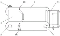
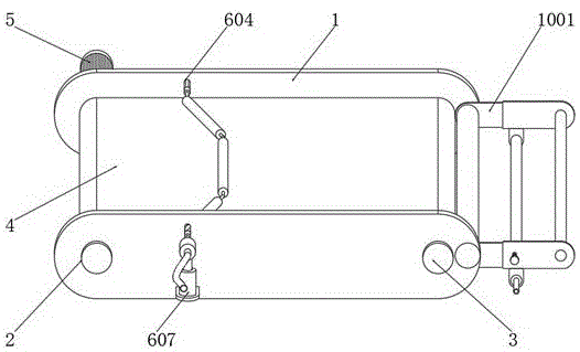
图1是本实用新型的结构示意图;Fig. 1 is the structural representation of the present utility model;
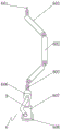
图2是本实用新型中间筒的安装结构示意图;Fig. 2 is the installation structure schematic diagram of the intermediate cylinder of the present utility model;
图3是本实用新型导热铝合金管的安装结构示意图;3 is a schematic diagram of the installation structure of the heat-conducting aluminum alloy tube of the present invention;
图4是本实用新型引导组件的结构示意图;4 is a schematic structural diagram of the guide assembly of the present invention;
图中标号:1、挡板;2、主动辊;3、从动辊;4、传送带;5、电机;Labels in the figure: 1, baffle; 2, driving roller; 3, driven roller; 4, conveyor; 5, motor;
6、防堵送布组件;601、安装管;602、中间筒;603、端筒;604、导向孔;605、限位活动块;606、连接套管;607、电推杆;608、支撑板;6. Anti-clogging cloth feeding assembly; 601, installation pipe; 602, middle cylinder; 603, end cylinder; 604, guide hole; 605, limit movable block; 606, connecting sleeve; 607, electric push rod; 608, support plate;
7、导热铝合金管;8、导热橡胶套;9、软管;7. Thermally conductive aluminum alloy tube; 8. Thermally conductive rubber sleeve; 9. Hose;
10、引导组件;1001、引导板;1002、第一引导辊;1003、引导套管;1004、安装板;1005、张紧辊;1006、第二引导辊。10. Guide assembly; 1001, guide plate; 1002, first guide roller; 1003, guide sleeve; 1004, mounting plate; 1005, tension roller; 1006, second guide roller.
具体实施方式Detailed ways
以下结合附图对本实用新型的优选实施例进行说明,应当理解,此处所描述的优选实施例仅用于说明和解释本实用新型,并不用于限定本实用新型。The preferred embodiments of the present utility model will be described below with reference to the accompanying drawings. It should be understood that the preferred embodiments described herein are only used to illustrate and explain the present utility model, but not to limit the present utility model.
实施例:如图1-4所示,本实用新型提供一种技术方案,一种基于布料定型机的防堵型送布装置,包括挡板1,两个挡板1之间一端安装有主动辊2,两个挡板1之间另一端安装有从动辊3,主动辊2和从动辊3之前安装有传送带4,主动辊2一端与电机5输出轴相连,电机5输入端与外部电源输出端电性相连;Embodiment: As shown in Figures 1-4, the present utility model provides a technical solution, an anti-blocking type cloth feeding device based on a cloth setting machine, comprising a baffle 1, and an active plate is installed at one end between the two baffles 1.
两个挡板1之间位于传送带4顶面位置处设置有防堵送布组件6,防堵送布组件6包括安装管601、中间筒602、端筒603、导向孔604、限位活动块605、连接套管606、电推杆607和支撑板608;An anti-blocking cloth feeding assembly 6 is provided between the two baffles 1 at the top surface of the conveyor belt 4. The anti-blocking cloth feeding assembly 6 includes a
安装管601活动安装于两个挡板1之间,安装管601中部转动套接有中间筒602,安装管601两端均转动套接有端筒603,中间筒602和端筒603两端位于安装管601位置处均套接有限位环,防止中间筒602和端筒603脱落,两个端筒603之间的夹角为120°,随着布料的输送,端筒603随之转动,进而将布料向两端摊开,消除皱折,中间筒602和端筒603外侧固定套接有导热铝合金管7,导热铝合金管7外侧套接有导热橡胶套8,安装管601一端连接有软管9,便于向安装管601内部通入热水,使得导热铝合金管7和导热橡胶套8升温,消除布料表面细小的皱折,挡板1位于安装管601两端位置处均开设有导向孔604,安装管601两端位于导向孔604内部处均套接有限位活动块605,限位活动块605对应导向孔604位置处开设有限位槽,导向孔604边缘镶嵌于限位槽内,防止限位活动块605脱离导向孔604,安装管601两端均套接有连接套管606,连接套管606底端连接有电推杆607,电推杆607底端安装有支撑板608,支撑板608固定安装于挡板1外侧,电推杆607输入端与外部电源输出端电性相连。The
两个挡板1之间端部位置处安装有引导组件10,引导组件10包括引导板1001、第一引导辊1002、引导套管1003、安装板1004、张紧辊1005和第二引导辊1006;A
引导板1001安装于挡板1一端,两个引导板1001之间转动安装有第一引导辊1002,引导板1001一端套接有引导套管1003,引导套管1003靠近引导板1001一端处安装有定位螺杆,便于固定引导套管1003,引导套管1003底端焊接有安装板1004,两个安装板1004之间转动安装有张紧辊1005,两个引导套管1003一端安装有第二引导辊1006。The
本实用新型的工作原理及使用流程:布料依次穿过第二引导辊1006上方、张紧辊1005下方和第一引导辊1002上方至传送带4处进行送布,此时拉动引导套管1003扩大第二引导辊1006和第一引导辊1002之间的间距,对布料进行张紧,同时也可调整第二引导辊1006至出布位置的距离,使得布料输送更加平稳;The working principle and use process of the present utility model: the cloth is fed through the top of the
电机5带动主动辊2转动,电机5型号为70KTYZ,进而带动传送带4转动,布料穿过安装管601下方,启动电推杆607,电推杆607型号为LX600,电推杆607拉动引导套管1003,进而带动安装管601下移,限位活动块605沿着导向孔604滑动,中间筒602和端筒603均接触布料,随着布料的输送,端筒603随之转动,两个端筒603之间的夹角为120°,因端筒603转动方向与布料移动方向存在夹角,端筒603与布料表面之间摩擦力的分力向两侧拉伸布料,进而将布料向两端摊开,消除皱折,防止送布时因褶皱而堵塞;The
中间筒602和端筒603外侧固定套接有导热铝合金管7,导热铝合金管7外侧套接有导热橡胶套8,安装管601一端连接有软管9,便于向安装管601内部通入热水,使得导热铝合金管7和导热橡胶套8升温,熨平布料表面细小的皱折,使得布料更加平整。The outer side of the
最后应说明的是:以上所述仅为本实用新型的优选实例而已,并不用于限制本实用新型,尽管参照前述实施例对本实用新型进行了详细的说明,对于本领域的技术人员来说,其依然可以对前述各实施例所记载的技术方案进行修改,或者对其中部分技术特征进行等同替换。凡在本实用新型的精神和原则之内,所作的任何修改、等同替换、改进等,均应包含在本实用新型的保护范围之内。Finally, it should be noted that the above is only a preferred example of the present utility model, and is not intended to limit the present utility model. Although the present utility model has been described in detail with reference to the foregoing embodiments, for those skilled in the art, It is still possible to modify the technical solutions described in the foregoing embodiments, or perform equivalent replacements to some of the technical features. Any modification, equivalent replacement, improvement, etc. made within the spirit and principle of the present invention shall be included in the protection scope of the present invention.
Claims (7)
Priority Applications (1)
| Application Number | Priority Date | Filing Date | Title |
|---|---|---|---|
| CN202020584975.4U CN212197762U (en) | 2020-04-20 | 2020-04-20 | An anti-blocking type cloth feeding device based on cloth setting machine |
Applications Claiming Priority (1)
| Application Number | Priority Date | Filing Date | Title |
|---|---|---|---|
| CN202020584975.4U CN212197762U (en) | 2020-04-20 | 2020-04-20 | An anti-blocking type cloth feeding device based on cloth setting machine |
Publications (1)
| Publication Number | Publication Date |
|---|---|
| CN212197762U true CN212197762U (en) | 2020-12-22 |
Family
ID=73834077
Family Applications (1)
| Application Number | Title | Priority Date | Filing Date |
|---|---|---|---|
| CN202020584975.4U Expired - Fee Related CN212197762U (en) | 2020-04-20 | 2020-04-20 | An anti-blocking type cloth feeding device based on cloth setting machine |
Country Status (1)
| Country | Link |
|---|---|
| CN (1) | CN212197762U (en) |
Cited By (2)
| Publication number | Priority date | Publication date | Assignee | Title |
|---|---|---|---|---|
| CN117207514A (en) * | 2023-09-19 | 2023-12-12 | 广州新李汽车零部件有限公司 | Automatic shrink-drying machine for heat shrinkage pipe for processing automobile wire harness |
| CN117228407A (en) * | 2023-11-03 | 2023-12-15 | 美多绿汽车皮革(广州)有限公司 | Leather feeding auxiliary equipment |
-
2020
- 2020-04-20 CN CN202020584975.4U patent/CN212197762U/en not_active Expired - Fee Related
Cited By (3)
| Publication number | Priority date | Publication date | Assignee | Title |
|---|---|---|---|---|
| CN117207514A (en) * | 2023-09-19 | 2023-12-12 | 广州新李汽车零部件有限公司 | Automatic shrink-drying machine for heat shrinkage pipe for processing automobile wire harness |
| CN117207514B (en) * | 2023-09-19 | 2024-05-03 | 广州新李汽车零部件有限公司 | Automatic shrink-drying machine for heat shrinkage pipe for processing automobile wire harness |
| CN117228407A (en) * | 2023-11-03 | 2023-12-15 | 美多绿汽车皮革(广州)有限公司 | Leather feeding auxiliary equipment |
Similar Documents
| Publication | Publication Date | Title |
|---|---|---|
| CN210596586U (en) | Ironing device for textile processing | |
| CN107354644A (en) | A kind of Novel cloth dryer | |
| CN116005391B (en) | Geotextile hot roller ironing device | |
| CN110103582A (en) | A kind of plastic fruit bag production new equipment | |
| CN217705120U (en) | Printing equipment for textile fabric | |
| CN207313920U (en) | A kind of Novel cloth dryer | |
| CN108507278B (en) | One kind, which is dyed cloth, expects drying wrap-up | |
| CN112111884B (en) | A high-efficiency printing and dyeing device for textile production and its use method | |
| CN110450509A (en) | A pressing molding method for plastic drainage board | |
| CN206298187U (en) | Dust removal and feeding device for feeder | |
| CN220867760U (en) | Fabric ironing device | |
| CN207567488U (en) | A kind of printing and dyeing fabrics fixation steaming machine | |
| CN111023770A (en) | Drying ovens for processing textile products | |
| CN206721537U (en) | A kind of tensionless winkler foundation pressure press | |
| CN215366398U (en) | Two-side heating, squeezing, dehumidifying and flattening machine | |
| CN211171251U (en) | Ironing device for garment processing | |
| CN116084128A (en) | Flattening and wrinkle-removing machine for textile fabric processing | |
| CN222100411U (en) | Double-sided ironing device for composite cloth | |
| CN209194239U (en) | A kind of two-sided sizing structure of high temperature resistant stainless steel lining paper drying cylinder | |
| CN211079663U (en) | A textile fabric setting device | |
| CN221000130U (en) | Sizing mechanism for clothing accessory production | |
| CN223720410U (en) | External electromagnetic auxiliary heating roller machine | |
| CN217165131U (en) | Gluing device for conical bobbins | |
| CN218749848U (en) | Double-color label printing machine with drying function | |
| CN219735879U (en) | Textile dryer capable of rotating and winding |
Legal Events
| Date | Code | Title | Description |
|---|---|---|---|
| GR01 | Patent grant | ||
| GR01 | Patent grant | ||
| CF01 | Termination of patent right due to non-payment of annual fee | ||
| CF01 | Termination of patent right due to non-payment of annual fee |
Granted publication date: 20201222 |