CN212194873U - Door plant engraver with dust absorption function - Google Patents
Door plant engraver with dust absorption function Download PDFInfo
- Publication number
- CN212194873U CN212194873U CN202020666723.6U CN202020666723U CN212194873U CN 212194873 U CN212194873 U CN 212194873U CN 202020666723 U CN202020666723 U CN 202020666723U CN 212194873 U CN212194873 U CN 212194873U
- Authority
- CN
- China
- Prior art keywords
- engraving machine
- box body
- dust
- collecting box
- fan
- Prior art date
- Legal status (The legal status is an assumption and is not a legal conclusion. Google has not performed a legal analysis and makes no representation as to the accuracy of the status listed.)
- Active
Links
- 239000000428 dust Substances 0.000 title claims abstract description 48
- 238000010521 absorption reaction Methods 0.000 title claims abstract description 9
- 230000007246 mechanism Effects 0.000 claims abstract description 16
- 238000007664 blowing Methods 0.000 claims description 9
- 230000000712 assembly Effects 0.000 claims description 6
- 238000000429 assembly Methods 0.000 claims description 6
- 241001233242 Lontra Species 0.000 claims description 3
- 230000036541 health Effects 0.000 abstract description 6
- 239000012634 fragment Substances 0.000 description 5
- 230000008901 benefit Effects 0.000 description 3
- 230000004048 modification Effects 0.000 description 3
- 238000012986 modification Methods 0.000 description 3
- 230000000694 effects Effects 0.000 description 2
- 230000008859 change Effects 0.000 description 1
- 230000007547 defect Effects 0.000 description 1
- 238000005553 drilling Methods 0.000 description 1
- 238000004049 embossing Methods 0.000 description 1
- 238000005516 engineering process Methods 0.000 description 1
- 239000010977 jade Substances 0.000 description 1
- 238000010147 laser engraving Methods 0.000 description 1
- 238000004519 manufacturing process Methods 0.000 description 1
- 239000002184 metal Substances 0.000 description 1
- 238000003801 milling Methods 0.000 description 1
- 239000007787 solid Substances 0.000 description 1
Images


Landscapes
- Laser Beam Processing (AREA)
Abstract
The utility model discloses a door plate engraving machine with dust collection function, in particular to the technical field of door plate engraving machines, which comprises a support plate and an engraving machine body, wherein the engraving machine body is arranged at the top of the support plate, the bottom of the support plate is provided with a dust collection mechanism, and the dust collection mechanism extends to the top of the engraving machine body; the dust collection mechanism comprises a box body, the box body is arranged at the top of the supporting plate, and a fan is fixedly arranged in the box body; the utility model discloses a dust absorption mechanism's design, the piece that accessible fan isotructure produced engraver body during operation blows off, and the bottom of engraver body is aimed at always to the wind-force that can also make the hose blow off, avoided the piece to pile up on the door plant always to can collect dust and piece, guarantee the normal work of engraver body, can avoid the dust to fly upward everywhere simultaneously, guaranteed the operational environment at present, and then avoided causing the problem of threat to the safety and the health of staff at present.
Description
Technical Field
The utility model relates to a door plant engraver technical field, concretely relates to door plant engraver with dust absorption function.
Background
The engraving is a drilling and milling combined processing in principle, a plurality of data input modes of an engraving machine have more free edges as required, a computer engraving machine has two types of laser engraving and mechanical engraving, the two types have high power and low power, the application range of the engraving machine is very wide, so that the most suitable application range of various engraving machines needs to be known, the low power is only suitable for manufacturing bicolor plates, building models, small-sized labels, three-dimensional artware and the like, the power required for engraving jade, metal and the like is more than 1500W, and the high-power engraving machine can be used as a small-power engraving machine and is most suitable for large-scale cutting, embossing and engraving.
The prior art has the following defects: the engraver is when carrying out sculpture work, and the tool bit fly-cutting can produce a large amount of sweeps, dust and pile up on the panel, only clears up after the door plant finishes carving completely usually, but when the sculpture, these sweeps are on the panel all the time, not only can produce certain influence to the sculpture effect, and the dust flies upward everywhere moreover, causes the threat to staff's safety and health on the spot.
Therefore, the invention is necessary to develop a door plate engraving machine with a dust suction function.
SUMMERY OF THE UTILITY MODEL
Therefore, the embodiment of the utility model provides a door plate engraving machine with a dust absorption function, through the design of a dust absorption mechanism, the scraps generated when the engraving machine body works can be blown away through the structures such as a fan and the like, but also can lead the wind power blown out by the hose to be always aligned with the bottom of the engraving machine body, thereby avoiding the debris from being always accumulated on the door panel, then the chips and dust generated by the operation of the engraving machine body can be adsorbed by structures such as an exhaust fan, and can collect dust and debris, ensure the normal work of the engraving machine body, simultaneously avoid the dust flying around, ensure the working environment on site, thereby avoiding the problem of threat to the safety and health of workers on site, solving the problem that the sweeps are always on the panel, not only having certain influence on the engraving effect, and the dust flies around, which threatens the safety and health of workers in the field.
In order to achieve the above object, the embodiment of the present invention provides the following technical solutions: a door plate engraving machine with a dust collection function comprises a supporting plate and an engraving machine body, wherein the engraving machine body is arranged at the top of the supporting plate, a dust collection mechanism is arranged at the bottom of the supporting plate, and the dust collection mechanism extends to the top of the engraving machine body;
the dust collection mechanism comprises a box body, the box body is arranged at the top of a support plate, a fan is fixedly arranged in the box body, an electric push rod is fixedly arranged at the bottom of the box body, the bottom of the electric push rod is fixedly connected with the top of the engraving machine body, two blowing assemblies are arranged on two sides of the fan, the two blowing assemblies penetrate through the box body and extend out of the bottom of the box body, each blowing assembly comprises a wind pipe, the wind pipe is arranged at the top of the fan and is communicated with the fan, the wind pipe is arranged in the box body and extends out of the bottom of the box body, a hose is fixedly arranged at the bottom of the wind pipe, a fixing ring is fixedly arranged outside the hose, a connecting rod is fixedly arranged on one side of the fixing ring, one end of the connecting rod is fixedly connected with one, a plurality of the connecting pipe top extends into a plurality of logical inslots respectively, the fixed air exhauster that is equipped with in collecting box inner chamber bottom, the inside fixed otter board that is equipped with of collecting box.
Preferably, vertical plates are fixedly arranged on two sides of the bottom of the supporting plate, and the collecting box is arranged between the two vertical plates.
Preferably, the fixed frame that is equipped with in backup pad top, fixed frame top both sides all are fixed to be equipped with the connecting plate.
Preferably, a fixing rod is arranged between the two connecting plates, a fixing block is arranged outside the fixing rod, and the bottom of the fixing block is fixedly connected with the top of the box body.
Preferably, the front side of the collecting box is provided with a movable door, and the movable door is connected with the collecting box through a hinge.
Preferably, the top of the supporting plate is provided with a workpiece, and the workpiece is arranged at the bottom of the engraving machine body.
Preferably, the exhaust fan is arranged at the bottom of the screen plate.
The embodiment of the utility model provides a have following advantage:
the utility model discloses a dust absorption mechanism's design, the piece that accessible fan isotructure produced engraver body during operation blows off, and the bottom of engraver body is aimed at always to the wind-force that can also make the hose blow off, avoided the piece to pile up on the door plant always, then piece and the dust that accessible air exhauster isotructure produced engraver body during operation adsorb, and can collect dust and piece, the normal work of engraver body has been guaranteed, can avoid the dust to fly upward everywhere simultaneously, on-the-spot operational environment has been guaranteed, and then the problem of threat has been caused to safety and health of staff on the spot to having avoided.
Drawings
In order to more clearly illustrate the embodiments of the present invention or the technical solutions in the prior art, the drawings used in the description of the embodiments or the prior art will be briefly described below. It should be apparent that the drawings in the following description are merely exemplary, and that other embodiments can be derived from the drawings provided by those of ordinary skill in the art without inventive effort.
The structure, ratio, size and the like shown in the present specification are only used for matching with the content disclosed in the specification, so as to be known and read by people familiar with the technology, and are not used for limiting the limit conditions which can be implemented by the present invention, so that the present invention has no technical essential significance, and any structure modification, ratio relationship change or size adjustment should still fall within the scope which can be covered by the technical content disclosed by the present invention without affecting the efficacy and the achievable purpose of the present invention.
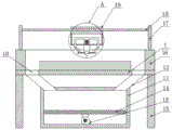
Fig. 1 is a schematic view of the overall structure provided by the present invention;
fig. 2 is a top view of the support plate provided by the present invention;
FIG. 3 is an enlarged view of the point A in FIG. 1 according to the present invention;
fig. 4 is a perspective view of the collecting box provided by the present invention;
in the figure: 1 backup pad, 2 engraver bodies, 3 boxes, 4 fans, 5 electric putter, 6 tuber pipes, 7 hoses, 8 solid fixed rings, 9 connecting rods, 10 logical grooves, 11 collecting boxes, 12 connecting pipes, 13 air exhauster, 14 otter boards, 15 vertical plates, 16 fixed frames, 17 connecting plates, 18 dead levers, 19 fixed blocks, 20 dodge gates.
Detailed Description
The present invention is described in terms of specific embodiments, and other advantages and benefits of the present invention will become apparent to those skilled in the art from the following disclosure. Based on the embodiments in the present invention, all other embodiments obtained by a person skilled in the art without creative work belong to the protection scope of the present invention.
Referring to the attached drawings 1-4 of the specification, the door plate engraving machine with the dust collection function comprises a supporting plate 1 and an engraving machine body 2, wherein the engraving machine body 2 is arranged at the top of the supporting plate 1, the bottom of the supporting plate 1 is provided with a dust collection mechanism, and the dust collection mechanism extends to the top of the engraving machine body 2;
the dust collection mechanism comprises a box body 3, the box body 3 is arranged at the top of a support plate 1, a fan 4 is fixedly arranged inside the box body 3, an electric push rod 5 is fixedly arranged at the bottom of the box body 3, the bottom of the electric push rod 5 is fixedly connected with the top of an engraving machine body 2, two blowing assemblies are respectively arranged at two sides of the fan 4, the two blowing assemblies penetrate through the box body 3 and extend out of the bottom of the box body 3, each blowing assembly comprises a wind pipe 6, the wind pipe 6 is arranged at the top of the fan 4 and is communicated with the fan 4, the wind pipe 6 is arranged inside the box body 3 and extends out of the bottom of the box body 3, a hose 7 is fixedly arranged at the bottom of the wind pipe 6, a fixing ring 8 is fixedly arranged outside the hose 7, a connecting rod 9 is fixedly arranged at one side of the fixing ring, the bottom of the supporting plate 1 is provided with a collecting box 11, the top of the collecting box 11 is fixedly provided with a plurality of connecting pipes 12, the top ends of the connecting pipes 12 extend into the through grooves 10 respectively, an exhaust fan 13 is fixedly arranged at the bottom of the inner cavity of the collecting box 11, and a screen plate 14 is fixedly arranged in the collecting box 11.
Furthermore, vertical plates 15 are fixedly arranged on two sides of the bottom of the supporting plate 1, and the collecting box 11 is arranged between the two vertical plates 15, so that the supporting plate 1 can be supported conveniently.
Further, fixed frame 16 that is equipped with in 1 top of backup pad, fixed frame 16 top both sides are all fixed and are equipped with connecting plate 17, avoid the dust departure backup pad 1 outside.
Furthermore, a fixing rod 18 is arranged between the two connecting plates 17, a fixing block 19 is arranged outside the fixing rod 18, and the bottom of the fixing block 19 is fixedly connected with the top of the box body 3, so that the box body 3 can be fixed conveniently.
Furthermore, a movable door 20 is arranged on the front side of the collecting box 11, and the movable door 20 is connected with the collecting box 11 through a hinge, so that debris in the collecting box 11 can be cleaned conveniently.
Further, a workpiece is arranged at the top of the supporting plate 1 and is arranged at the bottom of the engraving machine body 2.
Further, the exhaust fan 13 is arranged at the bottom of the mesh plate 14, so that debris is prevented from entering the interior of the exhaust fan 13.
The implementation scenario is specifically as follows: when the utility model is used, firstly, an external power supply is connected, then, a door plate to be carved is placed on the supporting plate 1, the door plate is positioned between the through grooves 10, when the carving machine body 2 works, the fan 4 can be started, the fan 4 works to transmit wind into the wind pipe 6, and then the wind pipe 6 transmits the wind into the hose 7, because the fixing ring 8 is fixedly arranged outside the hose 7, the bottom end of the hose 7 can be fixed, so that the wind blown out from the hose 7 can be always aligned with the bottom of the carving machine body 2, when the electric push rod 5 works to drive the carving machine body 2 to move up and down, the electric push rod 5 can also drive the connecting rod 9 to move up and down, the connecting rod 9 moves up and down to drive the fixing ring 8 to move, the fixing ring 8 can drive the hose 7 to move up and down, the hose 7 can be always aligned with the bottom of the, can blow away the redundant bits of expense and dust carved out of the engraving machine body 2 during the operation, meanwhile, because the top of the supporting plate 1 is provided with the fixing frame 16, the dust and the fragments can be prevented from being blown out of the supporting plate 1, the exhaust fan 13 is started at the same time, the suction force can be generated inside the collecting box 11 when the exhaust fan 13 works, then the suction force is transmitted to the top of the supporting plate 1 through the connecting pipe 12, the fragments and the dust blown away by the fan 4 can be adsorbed, through the design of the dust absorption mechanism, the fragments generated during the operation of the engraving machine body 2 can be blown away through the structures of the fan 4 and the like, the wind force blown out by the hose 7 can be always directed at the bottom of the engraving machine body 2, the fragments are prevented from being accumulated on the door plate all the time, then the fragments and the dust generated during the operation of the engraving machine body 2 can be adsorbed through the structures of the exhaust fan, meanwhile, dust can be prevented from flying around, the field working environment is guaranteed, and the problem of threat to the safety and health of workers in the field is further avoided.
Although the invention has been described in detail with respect to the general description and the specific embodiments, it will be apparent to those skilled in the art that modifications and improvements can be made based on the invention. Therefore, such modifications and improvements are intended to be within the scope of the invention as claimed.
Claims (7)
1. The utility model provides a door plant engraver with dust absorption function, includes backup pad (1) and engraver body (2), its characterized in that: the engraving machine body (2) is arranged at the top of the supporting plate (1), the bottom of the supporting plate (1) is provided with a dust collection mechanism, and the dust collection mechanism extends to the top of the engraving machine body (2);
the dust collection mechanism comprises a box body (3), the box body (3) is arranged at the top of a support plate (1), a fan (4) is fixedly arranged inside the box body (3), an electric push rod (5) is fixedly arranged at the bottom of the box body (3), the bottom of the electric push rod (5) is fixedly connected with the top of an engraving machine body (2), two blowing assemblies are arranged on two sides of the fan (4) respectively, the two blowing assemblies penetrate through the box body (3) and extend out of the bottom of the box body (3), each blowing assembly comprises a wind pipe (6), the wind pipe (6) is arranged at the top of the fan (4) and communicated with the fan (4), the wind pipe (6) is arranged inside the box body (3) and extends out of the bottom of the box body (3), a hose (7) is fixedly arranged at the bottom of the wind pipe (6), a fixing ring (8) is fixedly arranged outside the hose (7), a, connecting rod (9) one end and electric putter (5) one side fixed connection, a plurality of logical grooves (10) have been seted up on backup pad (1), backup pad (1) bottom is equipped with collecting box (11), collecting box (11) top is fixed and is equipped with a plurality of connecting pipes (12), and is a plurality of inside connecting pipe (12) top extends into a plurality of logical grooves (10) respectively, collecting box (11) inner chamber bottom is fixed and is equipped with air exhauster (13), collecting box (11) inside fixed otter board (14) that is equipped with.
2. The door plate engraving machine with the dust suction function according to claim 1, characterized in that: the bottom of the supporting plate (1) is fixedly provided with vertical plates (15) on two sides, and the collecting box (11) is arranged between the two vertical plates (15).
3. The door plate engraving machine with the dust suction function according to claim 1, characterized in that: fixed frame (16) that are equipped with in backup pad (1) top, fixed frame (16) top both sides are all fixed and are equipped with connecting plate (17).
4. The door plate engraving machine with the dust suction function according to claim 3, characterized in that: a fixing rod (18) is arranged between the two connecting plates (17), a fixing block (19) is arranged outside the fixing rod (18), and the bottom of the fixing block (19) is fixedly connected with the top of the box body (3).
5. The door plate engraving machine with the dust suction function according to claim 1, characterized in that: the collecting box (11) is characterized in that a movable door (20) is arranged on the front side of the collecting box (11), and the movable door (20) is connected with the collecting box (11) through a hinge.
6. The door plate engraving machine with the dust suction function according to claim 1, characterized in that: the top of the supporting plate (1) is provided with a workpiece, and the workpiece is arranged at the bottom of the engraving machine body (2).
7. The door plate engraving machine with the dust suction function according to claim 1, characterized in that: the exhaust fan (13) is arranged at the bottom of the screen plate (14).
Priority Applications (1)
| Application Number | Priority Date | Filing Date | Title |
|---|---|---|---|
| CN202020666723.6U CN212194873U (en) | 2020-04-27 | 2020-04-27 | Door plant engraver with dust absorption function |
Applications Claiming Priority (1)
| Application Number | Priority Date | Filing Date | Title |
|---|---|---|---|
| CN202020666723.6U CN212194873U (en) | 2020-04-27 | 2020-04-27 | Door plant engraver with dust absorption function |
Publications (1)
| Publication Number | Publication Date |
|---|---|
| CN212194873U true CN212194873U (en) | 2020-12-22 |
Family
ID=73827490
Family Applications (1)
| Application Number | Title | Priority Date | Filing Date |
|---|---|---|---|
| CN202020666723.6U Active CN212194873U (en) | 2020-04-27 | 2020-04-27 | Door plant engraver with dust absorption function |
Country Status (1)
| Country | Link |
|---|---|
| CN (1) | CN212194873U (en) |
Cited By (1)
| Publication number | Priority date | Publication date | Assignee | Title |
|---|---|---|---|---|
| CN112757826A (en) * | 2021-01-22 | 2021-05-07 | 钦州华安陶艺有限公司 | Nixing pottery finished product blank art decoration engraving device |
-
2020
- 2020-04-27 CN CN202020666723.6U patent/CN212194873U/en active Active
Cited By (1)
| Publication number | Priority date | Publication date | Assignee | Title |
|---|---|---|---|---|
| CN112757826A (en) * | 2021-01-22 | 2021-05-07 | 钦州华安陶艺有限公司 | Nixing pottery finished product blank art decoration engraving device |
Similar Documents
| Publication | Publication Date | Title |
|---|---|---|
| CN206510660U (en) | An all-round lifting engraving machine | |
| CN211614429U (en) | A drilling device with high safety performance | |
| CN211252007U (en) | A high-efficient five-axis linkage engraver for furniture processing | |
| CN211250379U (en) | Plate punching device for architectural decoration | |
| CN212888095U (en) | Dust collecting device for wood carving machine | |
| CN214023615U (en) | Perforating machine for door and window production | |
| CN211992061U (en) | Automatic chip removal device of three-in-one rotary machining center | |
| CN109226865A (en) | A kind of smart-cut device of hardware products manufacture | |
| CN206048357U (en) | A kind of foam sponge automatic drilling device of turning | |
| CN210588373U (en) | Engraver convenient to retrieve waste material | |
| CN209887202U (en) | Hardware drilling device capable of reducing noise and removing dust | |
| CN210309716U (en) | Engraving machine for double-head numerical control furniture processing | |
| CN210791323U (en) | Plate drilling device for building | |
| CN216827638U (en) | A construction site punching device | |
| CN221415114U (en) | A drilling device with dust suction function | |
| CN218343153U (en) | Engraving machine | |
| CN219359723U (en) | Diversified engraver of bamboo board material | |
| CN211333659U (en) | Plank engraver of synchronous dust absorption | |
| CN206436334U (en) | A kind of novel drilling machine | |
| CN212705409U (en) | Energy-saving aluminum alloy template processing equipment | |
| CN215751647U (en) | Can clear up engraver of sweeps automatically | |
| CN214236356U (en) | Novel drilling for building workpiece device | |
| CN212329728U (en) | A rapid drilling device for aluminum profiles | |
| CN213380440U (en) | Full-automatic engraving machine for surface machining of copper swinging plate | |
| CN221271630U (en) | Wall drilling device |
Legal Events
| Date | Code | Title | Description |
|---|---|---|---|
| GR01 | Patent grant | ||
| GR01 | Patent grant |