CN212183145U - Charging platform - Google Patents
Charging platform Download PDFInfo
- Publication number
- CN212183145U CN212183145U CN202020221437.9U CN202020221437U CN212183145U CN 212183145 U CN212183145 U CN 212183145U CN 202020221437 U CN202020221437 U CN 202020221437U CN 212183145 U CN212183145 U CN 212183145U
- Authority
- CN
- China
- Prior art keywords
- charging unit
- contact
- platform
- charging
- charging platform
- Prior art date
- Legal status (The legal status is an assumption and is not a legal conclusion. Google has not performed a legal analysis and makes no representation as to the accuracy of the status listed.)
- Active
Links
Images


Abstract
The charging platform can supply power to the lamp in a contact charging mode and can also supply power to the lamp in a wireless charging mode, and when the charging platform is used on the upper wall, the adsorption effect between the charging platform and the wall can be enhanced.
Description
Technical Field
The utility model relates to the field of charging especially involves charging platform.
Background
The electric energy is the most widely used energy in daily life at present, and people's life and work are difficult to leave the electric energy, and the electric power equipment of a great variety all relies on the electric energy to work.
Light fixtures are one of the common electrical devices, especially portable light fixtures. The lamp generally has the power storage capacity, so that the lamp can be used for a long time, and once the electric energy stored in the lamp is insufficient, an external power supply is required to be supplied with power.
At present, two ways of obtaining electric energy from the lamp are mainly provided, one is to externally connect a power supply in a wired way, and the other is to transmit electric energy in a wireless way. The latter approach has great application prospects due to its convenience of use.
In detail, the lamp can be placed on the surface of a power supply device, and the lamp can obtain electric energy from the power supply device without being connected with the power supply device through a conducting element such as a wire. When a user wants to use the lamp, the lamp can be taken down from the power supply device. The electric energy transmission of the lamp and the power supply device mainly adopts electromagnetic induction, the coil of the receiving end and the coil of the transmitting end are utilized to transmit electric energy, the electric energy transmission can be completed as long as the coil of the receiving end and the coil of the transmitting end are within a certain range, and the use is very convenient.
For most lamps, due to the cost problem, the factory of the lamps is not pre-equipped with a coil for wireless transmission, so the current power supply device can only supply power to the lamps pre-equipped with the wireless coil, which undoubtedly limits the application range of the power supply device.
The current wireless transmission efficiency cannot be compared with the wired transmission efficiency, so that the wireless transmission is more applied to small-sized lamps with smaller electric energy requirements, and once a large-sized lamp needs to be powered, if a wireless transmission technology is adopted, enough electric energy can be supplied for a long time.
Furthermore, the wired charging mode requires the power supply device and the electronic equipment to be connected through the power transmission line, so that certain requirements are required for the type and length of the power transmission line, the charging interface is easy to damage due to long-time plugging and unplugging, and is inconvenient in practical use,
SUMMERY OF THE UTILITY MODEL
An object of the utility model is to provide a charging platform, wherein charging platform can charge for lamps and lanterns conveniently.
Another object of the utility model is to provide a charging platform, wherein charging platform can charge for the lamps and lanterns that do not have the wireless charging coil of pre-installation.
Another object of the present invention is to provide a charging platform, wherein the charging platform can supply power for the lamp at a faster rate.
Another object of the present invention is to provide a charging platform, wherein the charging platform can supply power to a plurality of devices simultaneously.
Another object of the present invention is to provide a charging platform, wherein the charging platform can provide a contact charging mode and a wireless charging mode simultaneously.
Another object of the present invention is to provide a charging platform, wherein the charging platform can be switched between a contact charging mode and a wireless charging mode, and the user can select a suitable charging mode corresponding to the type of the power demand equipment or the power consumption requirement.
According to one aspect of the utility model, the utility model provides a charging platform which is suitable for providing electric energy for at least one lamp, wherein the charging platform comprises a contact charging unit, wherein the contact charging unit comprises a charging unit body, at least one conductive contact and a bearing surface, the charging unit body comprises a contact charging unit shell and a power storage unit, wherein the power storage unit is arranged on the contact charging unit shell, at least part of the surface of the charging unit body forms the bearing surface, the conductive contact is conductively connected to the electricity storage unit and at least a part of the conductive contact is exposed to the receiving surface side, when the lamp is placed on the receiving surface and aligned with the conductive contacts, electrical energy is transferred between the electrical storage unit and the lamp through the conductive contacts.
According to the utility model discloses an embodiment, the charging unit body further includes a setting element, wherein the setting element set up in contact charging platform casing and place when this lamps and lanterns in charging platform's preset position, this lamps and lanterns of setting element location in order to keep this lamps and lanterns with charging platform's position relatively fixed.
According to the utility model discloses an embodiment, the setting element is a magnetism and inhales the setting element, and this lamps and lanterns are configured with the location fitting piece, and magnetism is inhaled the setting element and this location fitting piece and can be inhaled each other magnetism with this lamps and lanterns of location in charging platform.
According to an embodiment of the invention, the positioning element comprises a clamping arm, wherein the clamping arm is rotatable to form a clamping space with the contact charging unit housing, the lamp being clampable to be held in the clamping space and aligned to the conductive contact.
According to an embodiment of the utility model, electrically conductive contact by elasticity telescopically support in the contact charging platform body.
According to the utility model discloses an embodiment, charging platform further includes one from magnetism to inhale the piece, wherein from magnetism inhale the piece set up in contact charging platform and with it carries face one side back of the body mutually, need be by the upper wall when this lamps and lanterns, inhale the piece from magnetism and be suitable for magnetism to inhale in the wall.
According to the utility model discloses an embodiment, charging platform further includes a reinforcing piece, wherein the reinforcing piece covers inhale the piece from magnetism and expose at least part of surface, and at least part protrusion in the surface of contact charging unit of reinforcing piece works as charging platform is inhaled the wall by magnetism, is located inhale from magnetism between piece and the wall the reinforcing piece is in inhale from magnetism and inhale the effect from magnetism of piece and wall and be extruded in the wall so that frictional force between charging platform and the wall strengthens.
According to an embodiment of the utility model, be located inhale from magnetism between piece and the wall the thickness of reinforcing part is no longer than 1.2 mm.
According to an embodiment of the present invention, the charging platform further includes a transmitting coil, wherein the transmitting coil is disposed on the charging unit body, and when the lamp is a wireless charging lamp and is aligned with the transmitting coil, the transmitting coil is placed on the receiving surface, and the lamp is powered wirelessly.
According to an embodiment of the present invention, the charging platform further comprises a wireless charging unit, wherein the wireless charging unit comprises a transmitting coil and a wireless charging unit housing, wherein the transmitting coil is disposed in the wireless charging unit housing and is conductively connected to the power storage unit, wherein the charging platform has a folded state and an unfolded state and is operable to be changed between the folded state and the unfolded state, the folded state, the contact charging unit is folded in the wireless charging unit, the unfolded state, the contact charging unit is disposed with the conductive contact side and the wireless charging unit is disposed with the transmitting coil side being exposed simultaneously.
According to an embodiment of the present invention, in the folded state, an inner surface of a contact charging unit of the contact charging unit is folded on an inner surface of a wireless charging unit of the wireless charging unit, wherein the contact charging unit inner surface and a contact charging unit outer surface are disposed opposite each other, the wireless charging unit inner surface and a wireless charging outer surface are disposed opposite each other, in the unfolded state, at least portions of the contact charging unit inner surface of the contact charging unit and the wireless charging unit inner surface are exposed, wherein the contact charging unit is movably connected to the wireless charging unit to change a relative position of the contact charging unit inner surface and the wireless charging unit inner surface, so that the charging platform is switched between the folded state and the unfolded state, wherein the conductive contact is disposed on one side of the inner surface of the contact charging unit; or the transmitting coil is disposed on an inner surface side of the wireless charging unit.
According to an embodiment of the present invention, the contact charging unit is slidably connected to the wireless charging unit.
According to an embodiment of the present invention, the contact charging unit is rotatably connected to the wireless charging unit, wherein the charging platform further comprises a rotating member, wherein the rotating member is located the wireless charging unit and the edge position of the contact charging unit and respectively connected to the wireless charging unit and the contact charging unit, by the rotating member, the wireless charging unit and the contact charging unit can rotate to form an included angle.
According to the utility model discloses an embodiment, contact charging unit by detachably block in wireless charging unit.
According to the utility model discloses a further aspect, the utility model provides a charging platform, wherein charging platform is provided with one and inhales piece and a reinforcing piece from magnetism, wherein inhale the piece from magnetism and be suitable for magnetism to inhale the wall, the reinforcing piece covers inhale the surface from magnetism at least part of piece and work as charging platform is inhaled the wall by magnetism, the at least part of reinforcing piece is located inhale from magnetism and inhale between piece and the wall, the reinforcing piece is in inhale the effect from magnetism of piece and wall and be extruded in the wall down, so that frictional force between charging platform and the wall increases.
According to an embodiment of the utility model, at least part of reinforcement protrusion in charging platform's surface.
According to an embodiment of the invention, the reinforcement is made of a rubber material.
Drawings
Fig. 1A is a schematic diagram of a charging platform according to a preferred embodiment of the present invention.
Fig. 1B is a schematic diagram of the charging platform according to the above preferred embodiment of the present invention.
Fig. 2 is a schematic application diagram of the charging platform according to the above preferred embodiment of the present invention.
Fig. 3 is a schematic application diagram of the charging platform according to another preferred embodiment of the present invention.
Fig. 4 is a schematic application diagram of the charging platform according to another preferred embodiment of the present invention.
Fig. 5 is a schematic application diagram of the charging platform according to another preferred embodiment of the present invention.
Fig. 6 is a schematic application diagram of the charging platform according to another preferred embodiment of the present invention.
Fig. 7 is a schematic diagram of the charging platform according to another preferred embodiment of the present invention.
Fig. 8A is a schematic diagram of a charging platform according to a preferred embodiment of the present invention.
Fig. 8B is a schematic diagram of the charging platform according to the above preferred embodiment of the present invention.
Fig. 9A is a schematic diagram of a charging platform according to another preferred embodiment of the present invention.
Fig. 9B is a schematic view of the charging platform according to the above preferred embodiment of the present invention.
Fig. 10A is a schematic diagram of a charging platform according to another preferred embodiment of the present invention.
Fig. 10B is a schematic view of the charging platform according to the above preferred embodiment of the present invention.
Fig. 11A is a schematic diagram of a charging platform according to another preferred embodiment of the present invention.
Fig. 11B is a schematic view of the charging platform according to the above preferred embodiment of the present invention.
Detailed Description
The following description is presented to disclose the invention so as to enable any person skilled in the art to practice the invention. The preferred embodiments in the following description are given by way of example only, and other obvious variations will occur to those skilled in the art. The basic principles of the invention, as defined in the following description, may be applied to other embodiments, variations, modifications, equivalents and other technical solutions without departing from the spirit and scope of the invention.
It will be understood by those skilled in the art that in the present disclosure, the terms "longitudinal," "lateral," "upper," "lower," "front," "rear," "left," "right," "vertical," "horizontal," "top," "bottom," "inner," "outer," and the like are used in a generic and descriptive sense only and not for purposes of limitation, as the terms are used in the description to indicate that the referenced device or element must have the specified orientation, be constructed and operated in the specified orientation, and not for the purpose of limitation.
It is understood that the terms "a" and "an" should be interpreted as meaning that a number of one element or element is one in one embodiment, while a number of other elements is one in another embodiment, and the terms "a" and "an" should not be interpreted as limiting the number.
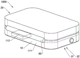
Referring to fig. 1A to 2, a charging platform 1000 according to a preferred embodiment of the present invention is illustrated. The charging platform 1000 can supply power to the lamp in a contact charging manner.
The charging platform 1000 can provide electric energy for various types of lamps, the lamps can be large lamps and can also be small lamps, and when the charging platform 1000 provides equipment for the large lamps, the electric energy transmitted by the charging platform 1000 can be transmitted to the lamp requiring electricity at a higher speed. It is understood that the charging platform 1000 may also be used to power other devices requiring power, such as a watch with contacts.
The power requiring device needs to be provided with contacts to receive power from the charging platform 1000. For wireless charging, the contact charges and need not dispose wireless coil, for wired charging, the contact charges and need not be disposed the charging wire, and is simple and convenient.
In detail, the charging platform 1000 includes a contact charging unit 10, wherein the contact charging unit 10 may include a charging unit body 11, at least one conductive contact 12 and a receiving surface 13, the charging unit body 11 includes a contact charging unit housing 111 and an electricity storage unit 112, wherein the electricity storage unit 112 is disposed in the contact charging unit housing 111, the contact charging unit housing 111 may form a contact charging unit receiving cavity 1110, and the electricity storage unit 112 is received in the contact charging unit receiving cavity 1110.
The conductive contacts 12 are provided to the charging unit body 11, for example, the contact charging unit housing 111 of the charging unit body 11. At least a part of the surface of the charging unit body 11 may form the receiving surface 13 for placing the lamp.
At least a part of the conductive contact 12 is exposed to the receiving surface 13 side. Optionally, the top surface of the conductive contact 12 and the receiving surface 13 are located on the same plane, or the top surface of the conductive contact 12 slightly protrudes from the receiving surface 13.
When the lamp is placed on the receiving surface 13 and aligned with the conductive contacts 12, electric energy can be transferred from the power storage unit 112 to the lamp through conduction between the conductive contacts 12 and the conductive elements provided in the lamp, so that the lamp can be charged.
It is noted that the conductive contact 12 is movably arranged, for example, the conductive contact 12 may be supported to the contact charging unit 10 housing by a resilient conductive member. The conductive contact 12 may protrude from the receiving surface 13, and when the lamp is placed on the receiving surface 13, under the action of gravity of the lamp, the conductive contact 12 is subjected to a downward pressing force and an elastic force of the elastic conductive member, so that the conductive contact 12 tends to move toward the lamp, and the conductive contact 12 and the lamp can be pressed, thereby facilitating stable conduction between the charging platform 1000 and the lamp.
It is understood that the charging platform 1000 does not represent a flat surface, for example, when the conductive contacts 12 are disposed to protrude from the receiving surface 13, the charging platform 1000 does not represent a flat surface.
Further, the charging unit body 11 of the contact charging unit 10 of the charging platform 1000 further includes a positioning element 113, wherein the positioning element 113 is disposed on the contact charging unit housing 111 of the contact charging unit 10, and when a lamp is placed on the receiving surface 13, the positioning element 113-can position the lamp on the receiving surface 13, so that the lamp can be aligned to the conductive contact 12 on one hand, and the stability of connection between the lamp and the conductive contact 12 on the other hand can be maintained.
In detail, in this embodiment, the positioning element 113 is a magnetic positioning element, and the lamp can be provided with a matching magnetic mating element, and the magnetic positioning element and the magnetic mating element can be magnetically coupled to each other. The magnetic attraction positioning piece can be a magnet or other magnetic substances. The magnetic attraction matching piece can be a magnet or other substances with magnetic attraction. The magnetic attraction matching part may be metal such as iron capable of being attracted by a magnetic substance, or, conversely, the magnetic attraction positioning part may be metal such as iron capable of being attracted by a magnetic substance.
The number of the positioning elements 113 may be two or more, and in this embodiment, the number of the positioning elements 113 is two. Through the magnetic attraction of the positioning member 113 of the charging platform 1000 and the magnetic attraction mating member of the lamp, the lamp can be aligned to the conductive contact 12 and positioned on the charging platform 1000.
Alternatively, the positioning members 113 may be distributed around the conductive contacts 12, or the conductive contacts 12 may be arranged around the positioning members 113.
Furthermore, the positioning element 113 may also be a snap positioning element, and the lamp may be provided with a snap fitting element. The clamping positioning piece can be a protrusion, the clamping fitting piece can be a recess, and when the lamp needs to be charged, the clamping positioning piece can extend into the clamping fitting piece to play a positioning role.
It is understood that the detachable positioning between the light fixture and the charging platform 1000 can be performed in other ways, which is only illustrated here by way of example.
Further, it is understood that the receiving surface 13 of the charging platform 1000 is not necessarily a plane, and with reference to fig. 3, another embodiment of the charging platform 1000 according to the present invention is illustrated. In this embodiment, the receiving surface 13 of the charging platform 1000 forms a receiving space 130, and a lamp can be held in the receiving space 130. The conductive contacts 12 are exposed to the receiving space 130 and distributed in the receiving space 130.
In detail, the receiving surface 13 is a concave structure, the lamp is supported on the receiving surface 13, and the conductive contacts 12 may be disposed on both sides of the lamp or circumferentially along the outer surface of the lamp. In this way, the structural design of the charging platform 1000 itself can limit the position of the lamp, for example, the lamp, which is generally cylindrical, is prevented from rolling on the surface of the charging platform 1000.
Referring to fig. 4, another embodiment of the charging platform 1000 according to the present invention is illustrated. In this embodiment, the charging platform 1000 is provided in a hollow cylindrical shape. The conductive contacts 12 are arranged on an inner wall of the charging platform 1000, and the lamp can be pushed into the charging platform 1000.
It is understood that the contact charging unit 10 of the charging platform 1000 may be configured to be able to maintain a relative position of the light fixture and the contact charging unit 10 when on the upper wall, for example, the receiving surface 13 is configured to be at least partially convex, so that when the charging platform 1000 is suspended vertically for use, the receiving surface 13 can support the light fixture in a vertical direction to enable the light fixture to maintain conduction with the conductive contacts 12 of the charging platform 1000. It should be noted that the receiving space 130 formed by the receiving surface 13 of the charging platform 1000 can be variable to adapt to different sizes of lamps.
Referring to fig. 5 or fig. 6, two other embodiments of the charging platform 1000 according to the above preferred embodiment of the present invention are illustrated.
In the present embodiment, the positioning member 113 of the charging platform 1000 is implemented as a clamping structure. The conductive contacts 12 are arranged on the positioning member 113 and the positioning member 113 can align the lamp with the conductive contacts 12 by clamping.
In detail, the positioning member 113 includes a first clamping arm 1131 and a second clamping arm 1132, and the first clamping arm 1131 and the second clamping arm 1132 are connected to each other and can be opened to form an opening through which the lamp enters between the first clamping arm 1131 and the second clamping arm 1132. When the first clamping arm 1131 and the second clamping arm 1132 are closed, the first clamping arm 1131 and the second clamping arm 1132 can clamp the lamp.
The conductive contact 12 is located inside the first clamping arm 1131 and/or the second clamping arm 1132, and when the lamp is clamped by the first clamping arm 1131 and the second clamping arm 1132, the conductive contact 12 contacts with a conductive element of the lamp, so as to conduct the lamp and the charging platform 1000.
It should be noted that the positioning member 113 may be a single clamping arm, such as shown in fig. 5, or two clamping arms, such as shown in fig. 6. When the positioning member 113 is a single holding arm, the holding arm is movable to be openably and closably mounted to the housing of the contact charging unit 10 to form a holding space 140. When the positioning member 113 is two holding arms, the holding space 140 is formed between the two holding arms.
Further, with reference to fig. 1B and fig. 2, the charging platform 1000 includes a self-magnetic attraction member 31, wherein the self-magnetic attraction member 31 is disposed on the contact charging unit 10, and the self-magnetic attraction member 31 is used for the contact charging unit 10 to be attached to a wall, for example, when the wall is made of iron, the self-magnetic attraction member 31 can magnetically attract the wall, so that the charging platform 1000 can be used on the wall. Since the positioning member 113 positions the lamp on the charging platform 1000, the lamp and the charging platform 1000 can be used together on the wall.
The contact charging unit housing 111 of the contact charging unit 10 forms a receiving cavity 300, wherein the self-magnetic attraction member 31 can be installed in the receiving cavity 300. Alternatively, the self-attracting member 31 and the contact charging unit housing 111 may be integrally formed.
The charging platform 1000 further comprises a reinforcing member 32, wherein the reinforcing member 32 is disposed on a surface of the self-attracting member 31, and when the charging platform 1000 is used on a wall, the reinforcing member 32 is located between the self-attracting member 31 and the wall.
In other words, the reinforcement 32 can be in contact with the wall. The reinforcement 32 can reinforce a frictional force between the charging platform 1000 and a wall to facilitate the charging platform 1000 to be stably suspended from the wall.
In detail, the reinforcement 32 of the charging platform 1000 is disposed to slightly protrude from the surface of the contact charging unit housing 111. When the charging platform 1000 is used on a wall, a magnetic attraction effect is generated between the self-magnetic attraction piece 31 of the charging platform 1000 and the wall capable of being magnetically attracted, and the reinforcing piece 32 is pressed to be tightly attached to the wall.
In this embodiment, the self-magnetic attraction member 31 is filled in the accommodating cavity 300, at least a portion of the reinforcing member 32 is accommodated in the accommodating cavity 300 and at least a portion of the reinforcing member extends out of the accommodating cavity 300, and when the charging platform 1000 is mounted on a wall, the reinforcing member 32 is pressed to a surface of the charging platform 1000, which is located on the same plane.
Further, in this embodiment, the thickness of the reinforcing member 32 between the self-attracting member 31 and the wall is not more than 1.5mm, for example, 1.2 mm. The reinforcing member 32 is too thick, which may affect the magnetic attraction between the self-attracting member and the wall.
Further, the surface of the reinforcement 32 may be rough, or the reinforcement 32 may be irregularly configured, which may help to increase the coefficient of friction between the reinforcement 32 itself and the wall.
In this way, compared to the self-magnetic attraction piece 31 directly attached to the wall, the charging platform 1000 can be more stably mounted on the wall by the reinforcing piece 32.
In this embodiment, the exposed portion of the self-attracting element 31 is completely covered by the reinforcing element 32. In another embodiment of the present invention, the reinforcing member 32 can cover a part of the surface of the self-attracting member 31, for example, a circular surface of the self-attracting member 31 is attached in an X-shape or a Y-shape.
The reinforcing member 32 may be, but is not limited to, a rubber material support, and covers the self-attracting member 31.
The reinforcement member 32 may be an elastic material, so that the reinforcement member 32 slightly protruding from the surface of the contact charging unit housing 111 can be pressed, and the pressed reinforcement member 32 may be pressed to be located on the same plane as the surface of the contact charging unit housing 111, so as to form a flat mounting surface on the charging platform 1000.
In the drawings, the wall is identified by reference numeral w.
Further, referring to fig. 7, another embodiment of the charging platform 1000 according to the above preferred embodiment of the present invention is illustrated.
The charging platform 1000 further comprises a transmitting coil 22, wherein the transmitting coil 22 is applied for wireless charging and is conductively connected to the power storage unit 112.
When the lamp is a cordless charging type lamp and is placed on the receiving surface 13 with respect to the transmission coil 22, the lamp can be powered wirelessly.
The conductive contacts 12 may be arranged around the transmitting coil 22, and when the luminaire is a cordless or rechargeable luminaire, the conductive contacts 12 do not interfere with the transfer of electrical energy between the transmitting coil 22 and the luminaire.
Further, the charging platform 1000 can be selected to be a wireless charging or a contact charging based on the type of the light fixture, the charging platform 1000 can also simultaneously supply power to two of the power demand devices,
referring to fig. 8A and 8B, the charging platform 1000 according to another preferred embodiment of the present invention is illustrated. The charging platform 1000 can provide a wireless charging mode and a contact charging mode, the infinite charging mode is to transmit electric energy by using an electromagnetic induction mode, direct physical contact is not required between a device providing electric energy and equipment requiring electric energy, the contact charging mode is to transmit electric energy by contacting substances of conductive entities, for example, the device providing electric energy is provided with contacts, the equipment requiring electric energy is also provided with the same contacts, and when the contacts of the device providing electric energy contact the contacts of the equipment requiring electric energy, the electric energy can be transmitted.
The charging platform 1000 can provide electric energy for various types of electric equipment, the electric equipment can be large-sized equipment or small-sized equipment, and when the charging platform 1000 provides electric energy for the large-sized equipment, the electric energy transferred by the charging platform 1000 can be transferred to the electric equipment at a higher speed.
The power requiring device is provided with at least one receiving coil, or not, and is capable of obtaining electrical power from the charging platform 1000. In other words, the charging platform 1000 can be widely used, and the power demand device is not required to be equipped with a wireless charging transmission accessory.
The charging platform 1000 can not only supply power to one power demand device, but also supply power to a plurality of power demand devices, and the charging platform 1000 can supply power to different power demand devices in a wireless charging mode and a contact charging mode. That is, when two power demand devices, one of which is designed to be charged wirelessly and the other of which is designed to be charged by wire, are provided, the charging platform 1000 can simultaneously supply power to the two power demand devices.
In detail, the charging platform 1000 includes a contact charging unit 10, a wireless charging unit 20 and a power storage unit 112, wherein the contact charging unit 10 is adapted to provide power to the power demand device in a contact charging manner, and the wireless charging unit 20 is adapted to provide power to the power demand device in a wireless charging manner. The power storage unit 112 is adapted to store electrical energy for providing electrical energy to the power demanding device.
The contact charging unit 10 includes a charging unit body 11 and a conductive contact 12, wherein the conductive contact 12 is conductively connected to the power storage unit 112 and is disposed on the charging unit body 11, and the power-requiring device externally connected to the contact charging unit 10 of the charging platform 1000 can obtain electric energy from the power storage unit 112 through the conductive contact 12.
The charging unit body 11 includes a contact charging unit housing 111 and a positioning member 113, wherein the positioning member 113 is disposed on the contact charging unit housing 111 to position a lamp or other power-requiring equipment.
The wireless charging unit 20 comprises a wireless charging unit housing 21 and at least one transmitting coil 22, wherein the transmitting coil 22 is disposed in the wireless charging unit housing 21, the transmitting coil 22 is conductively connected to the power storage unit 112, and the transmitting coil 22 of the wireless charging unit 20 is capable of cooperating with the receiving coil of the power demand device to transmit the electric energy from the power storage unit 112 to the receiving coil of the power demand device through the transmitting coil 22.
The contact charging unit 10 may include a contact charging unit housing 111 and the contact charging unit housing 111 may form a contact charging unit receiving cavity 1110. The wireless charging unit case 21 of the wireless charging unit 20 may form a wireless charging accommodation chamber 200. The power storage unit 112 may be accommodated in the contact charging unit accommodating chamber 1110 or the wireless charging accommodating chamber 200. Alternatively, the number of the power storage units 112 may be two, one power storage unit 112 is accommodated in the contact charging unit accommodating chamber 1110, and the other power storage unit 112 is accommodated in the wireless charging accommodating chamber 200.
Further, the contact charging unit 10 of the charging platform 1000 is stacked on the wireless charging unit 20, so that the size, especially the area size, of the charging platform 1000 is small.
When the contact charging unit 10 and the wireless charging unit 20 of the charging platform 1000 are stacked, the charging platform 1000 can provide a wireless charging platform 1000 or contact the charging platform 1000. It is to be understood that the platform generally refers to the environment or conditions in which a work is performed and is not intended to limit charging platform 1000 to a flat table. The charging platform 1000 can be operated such that the charging platform 1000 can provide both a wireless charging platform and a contact charging platform.
Specifically, the contact charging unit 10 of the charging platform 1000 is movably mounted to the wireless charging unit 20. When the contact charging unit 10 in a stacked state moves relative to the wireless charging unit 20 to change the relative position, the contact charging unit 10 or the wireless charging unit 20 can be simultaneously exposed, so that the charging platform 1000 can simultaneously provide two workable platforms.
In more detail, the contact charging unit 10 of the charging platform 1000 has a contact charging unit outer surface 101 and a contact charging unit inner surface 102, wherein the contact charging unit outer surface 101 and the contact charging unit inner surface 102 are oppositely disposed. The wireless charging unit 20 has a wireless charging unit inner surface 202 and a wireless charging unit outer surface 201, wherein the wireless charging unit inner surface 202 and the wireless charging unit outer surface 201 are disposed opposite to each other.
For example, the wireless charging unit 20 is located above the contact charging unit 10, and it is understood that the contact charging unit 10 may be located above the wireless charging unit 20. When the contact charging unit 10 is stacked on the wireless charging unit 20, the contact charging unit inner surface 102 of the contact charging unit 10 and the wireless charging unit inner surface 202 of the wireless charging unit 20 are overlapped with each other.
When the power demand device equipped with the receiving coil is placed on the wireless charging unit outer surface 201 of the wireless charging unit 20, the power demand device can be powered, and thus when the charging platform 1000 is in a folded state, the power demand device can be placed on the wireless charging unit outer surface 201 of the wireless charging unit 20 of the charging platform 1000 to be powered wirelessly. Since the contact charging unit 10 is located below the wireless charging unit 20, when the charging platform 1000 is in the folded state, the contact charging unit inner surface 102 of the contact charging unit 10 is not exposed to the outside, and thus it is difficult to supply power to the power demand device for contact power generation.
In the present embodiment, the wireless charging unit outer surface 201 of the wireless charging unit 20 and the contact charging unit inner surface 102 of the contact charging unit 10 are respectively used as charging areas. It is understood that in other embodiments of the present invention, the wireless charging unit inner surface 202 of the wireless charging unit 20 or the contact charging unit outer surface 101 of the contact charging unit 10 may also be used as a charging area.
Further, the charging platform 1000 can be deployed such that the wireless charging unit 20 and the contact charging unit 10 are simultaneously exposed, thereby simultaneously providing a region where power can be supplied to both of the power requiring devices.
In other words, the charging platform 1000 has the folded state and an unfolded state, and the charging platform 1000 is operable to be switched between the folded state and the unfolded state. In the folded state, the wireless charging unit 20 and the contact charging unit 10 of the charging platform 1000 are folded with each other, the charging platform 1000 cannot provide a charging area or provide a charging mode, and in the unfolded state, the wireless charging unit 20 and the contact charging unit 10 of the charging platform 1000 can provide two charging modes.
In this embodiment, the charging platform 1000 can provide a wireless charging area in the folded state. When the external surface 201 of the wireless charging unit 20 is a workable area, the charging platform 1000 in the folded state cannot wirelessly supply power to the power demand device.
Further, the charging platform 1000 includes a sliding assembly 40, wherein the sliding assembly 40 is respectively disposed on the wireless charging unit 20 and the contact charging unit 10, so that the wireless charging unit 20 and the contact charging unit 10 can slide relatively.
The sliding assembly 40 includes a first slider 41 and a second slider 42, wherein the first slider 41 is disposed on the wireless charging unit 20, the second slider 42 is disposed on the contact charging unit 10, and the first slider 41 and the second slider 42 are disposed in a face-to-face relationship.
In the present embodiment, the first sliding member 41 is located on a lower side of the wireless charging unit 20, i.e., on the side of the wireless charging unit inner surface 202, and the second sliding member 42 is located on an upper side of the contact charging unit 10, i.e., on the side of the contact charging unit inner surface 102.
The first sliding member 41 may be a sliding rail, and the second sliding member 42 may be a gear, a steel ball, or a pulley. Alternatively, the first sliding member 41 may be a gear, a steel ball or a pulley, and the second sliding member 42 may be a sliding rail.
The wireless charging unit 20 is slidably connected to the contact charging unit 10 by the relative sliding of the first slider 41 and the second slider 42.
Further, the number of the first sliders 41 may be two and disposed in parallel at the edge position of the wireless charging unit 20, and accordingly, the number of the second sliders 42 may be two and disposed in parallel at the edge position of the contact charging unit 10. The wireless charging unit 20 has a first end and a second end, and the second slider 42 extends between the first end and the second end. Optionally, the wireless charging unit 20 can move from the first end overlapping one side of the contact charging unit 10 to the first end overlapping the other side of the contact charging unit 10, so that at least a portion of the contact charging unit inner surface 102 of the contact charging unit 10 originally covered by the wireless charging unit 20 is exposed.
Alternatively, the wireless charging unit 20 and the contact charging unit 10 may be similar in size, or even identical, and when the wireless charging unit 20 is stacked on the contact charging unit 10, the wireless charging unit 20 and the contact charging unit 10 may be seen as a single unit.
When a user needs to simultaneously supply power to two such power demanding devices that obtain power in different ways, the charging platform 1000 can be shifted to the unfolded state so that the charging available areas of the wireless charging unit 20 and the contact charging unit 10 are simultaneously exposed.
It should be noted that, in the present embodiment, the charging available areas of the wireless charging unit 20 and the contact charging unit 10 of the charging platform 1000 are located on the same side. In another embodiment of the present invention, the charging area of the charging platform 1000 for the wireless charging unit 20 and the contact charging unit 10 can be located on two opposite sides.
In another embodiment of the present invention, the wireless charging unit 20 may be located below the contact charging unit 10. In the folded state, the charging platform 1000 may provide power in a contact charging manner, and in the unfolded state, the charging platform 1000 may provide power in a contact charging manner, or may provide power in a wireless charging manner.
Further, the number of the transmitting coils 22 of the wireless charging unit 20 may be plural, so that the wireless charging unit 20 can simultaneously provide power for a plurality of power demand devices, for example, two mobile phones may be placed side by side on the wireless charging unit 20 and respectively correspond to the transmitting coils 22 to be powered.
The number of the conductive contacts 12 of the contact charging unit 10 may be multiple, so that the conductive contacts 12 of the contact charging unit 10 can simultaneously provide power for multiple power demand devices, for example, two mobile phones can be respectively connected to the conductive contacts 12 to obtain power.
For the wireless charging unit 20, the power demanding device may be placed on the wireless charging unit 20 in a lying manner such that the receiving coil of the power demanding device and the transmitting coil 22 of the wireless charging unit 20 are aligned with each other.
For the contact charging unit 10, the power demand device may be placed on the contact charging unit 10 in a flat manner, or may be placed on the wireless charging unit 20 in a vertical manner.
The conductive contact 12 of the contact charging unit 10 may be provided movably, and when the conductive contact 12 is subjected to an external force, the conductive contact 12 is lowered so as not to be exposed, and when the force acting on the conductive contact 12 is removed, the conductive contact 12 is raised so as to be exposed.
The wireless charging unit inner surface 202 of the wireless charging unit 20 may be a plane, and the contact charging unit inner surface 102 of the contact charging unit 10 may be a plane, so that the wireless charging unit 20 and the contact charging unit 10 may be smoothly overlapped with each other. When the wireless charging unit 20 is stacked on the contact charging unit 10, the conductive contact 12 on the side of the contact charging unit inner surface 102 is pressed so as not to protrude from the contact charging unit inner surface 102. When the charging platform 1000 is deployed, the compressed conductive contacts 12 automatically spring out to protrude from the contact charging unit inner surface 102.
Further, in the present embodiment, the light fixture is placed on the contact charging unit 10 for charging, and a mobile phone is placed on the wireless charging unit 20 for charging. That is, the charging platform 1000 can also supply power to different types of the power demand devices. Of course, it is also possible that one of the light fixtures is placed on the contact charging unit 10 for charging and the other light fixture is placed on the wireless charging unit 20 for charging.
Further, the self-attracting member 31 and the reinforcing member 32 may be disposed on the contact charging unit 10 and/or the wireless charging unit 20. The type of the charging platform 1000 does not limit the application of the self-magnetic attraction member 31 and the reinforcing member 32.
Referring to fig. 9A and 9B, the charging platform 1000 according to another preferred embodiment of the present invention is illustrated.
In this embodiment, the charging platform 1000 includes the power storage unit 112, the wireless charging unit 20 and the contact charging unit 10, when the charging platform 1000 is in the folded state, at least parts of the wireless charging unit 20 and the contact charging unit 10 are folded with each other, and when the charging platform 1000 is in the unfolded state, the wireless charging unit 20 and the contact charging unit 10 can simultaneously supply power to the power demand device.
The wireless charging unit 20 includes the wireless charging unit case 21 and the transmitting coil 22, and the contact charging unit 10 includes the charging unit body 11 and the conductive contact 12. The charging unit body 11 includes the contact charging unit housing 111 and the positioning member 113.
It is understood that the positioning member 113 may be disposed on the wireless charging unit housing 21 of the wireless charging unit 20 for positioning the power demand device on the wireless charging unit 20. The positioning element 113 can fix the power-requiring device to the wireless charging unit 20 in various manners such as magnetic attraction, clamping, and limiting. Alternatively, in order to reduce the influence of the magnetic field on the power demand equipment, when the power demand equipment is an electronic equipment such as a mobile phone, the positioning member 113 may limit the power demand equipment in a mechanical fixing manner, such as clamping, clipping, and the like. The positioning member 113 may be implemented as a claw with a variable size, and clamps the power demand device from two sides or three sides to fix the power demand device at a predetermined position.
Further, the wireless charging unit 20 is rotatably connected to the contact charging unit 10. When the charging platform 1000 is in the folded state, the conductive contact 12 of the contact charging unit 10 or the transmitting coil 22 side of the wireless charging unit 20 is not exposed, so that the charging platform 1000 cannot provide power for the power demand device in both the contact charging mode and the wireless charging mode. When the charging platform 1000 is in the unfolded state, both the conductive contact 12 of the contact charging unit 10 and the transmission coil 22 side of the wireless charging unit 20 can be exposed, so that the charging platform 1000 can supply power to the power demand device in both the contact charging mode and the wireless charging mode.
The charging platform 1000 can be switched between the folded state and the unfolded state by turning over the wireless charging unit 20 or the contact unit.
In detail, the wireless charging unit 20 has a wireless charging unit outer surface 201 and a wireless charging unit inner surface 202, wherein the wireless charging unit outer surface 201 and the wireless charging unit inner surface 202 are disposed opposite to each other. The contact charging unit 10 has a contact charging unit outer surface 101 and a contact charging unit inner surface 102, wherein the contact charging unit outer surface 101 and the contact charging unit inner surface 102 are oppositely disposed.
The transmitting coil 22 is located on the side of the wireless charging unit inner surface 202. The conductive contact 12 is located on the side of the contact charging unit inner surface 102. When the charging platform 1000 is in the folded state, the wireless charging unit inner surface 202 of the wireless charging unit 20 is attached to the contact charging unit inner surface 102. Neither the transmitting coil 22 nor the conductive contact 12 can be exposed. When the charging platform 1000 is in the unfolded state, the wireless charging unit inner surface 202 of the wireless charging unit 20 is away from the contact charging unit inner surface 102 of the contact charging unit 10, so that the transmitting coil 22 and the conductive contact 12 can be exposed to the outside.
The wireless charging unit 20 and the contact charging unit 10 of the charging platform 1000 can form an included angle, and the size of the included angle can be changed. The included angle between the wireless charging unit 20 and the contact charging unit 10 may be 0 degree or 180 degrees. Alternatively, the wireless charging unit 20 and the contact charging unit 10 may be rotated to be located on the same plane.
Further, the wireless charging unit outer surface 201 of the wireless charging unit 20 and the contact charging unit outer surface 101 of the contact charging unit 10 may be located on the same plane, so that the charging platform 1000 in the unfolded state may be placed on a plane for use.
Further, the charging platform 1000 includes a rotating member 50, and the wireless charging unit 20 is rotatably connected to the contact charging unit 10 through the rotating member 50.
The rotation member 50 may be a rotation shaft to which the wireless charging unit 20 and the contact charging unit 10 are respectively mounted. It will be appreciated that by arranging the wireless charging unit 20, the contact charging unit 10 and the rotatable member 50, the charging platform 1000 can be placed on a flat table for use in the unfolded state and provide a flat power supply area, such as the wireless charging unit inner surface 202 of the wireless charging unit 20 and the contact charging unit inner surface 102 of the contact charging unit 10.
The wireless charging unit 20 may be pivotally, hingedly, or hingedly connected to the contact charging unit 10.
Further, it can be understood that, in the present embodiment, the conductive contact 12 and the transmitting coil 22 are both located on the contact charging unit inner surface 102 and the wireless charging unit inner surface 202, so that the charging platform 1000 cannot be powered by a contact charging manner or a wireless charging manner in the stacked state.
According to another embodiment of the present invention, the conductive contact 12 may be located on the side of the contact charging unit outer surface 101, and the transmitting coil 22 may be located on the side of the wireless charging unit inner surface 202. According to another embodiment of the present invention, the conductive contact 12 may be located on the side of the contact charging unit outer surface 101, and the transmitting coil 22 may be located on the side of the wireless charging unit outer surface 201. According to the present invention, the conductive contact 12 may be located on the side of the contact charging unit inner surface 102, and the transmitting coil 22 may be located on the side of the wireless charging unit outer surface 201.
Further, the charging platform 1000 further includes a locking member, wherein the wireless charging unit 20 and the contact charging unit 10 are connected by the rotating member 50 to be closed on one side, and the wireless charging unit 20 and the contact charging unit 10 are connected on the other side.
Referring to fig. 10A and 10B, the charging platform 1000 according to another preferred embodiment of the present invention is illustrated. In this embodiment, the charging platform 1000 includes the power storage unit 112, the wireless charging unit 20 and the contact charging unit 10, when the charging platform 1000 is in the folded state, at least parts of the wireless charging unit 20 and the contact charging unit 10 are folded with each other, and when the charging platform 1000 is in the unfolded state, the wireless charging unit 20 and the contact charging unit 10 can simultaneously supply power to the power demand device.
The wireless charging unit 20 includes the wireless charging unit housing 21 and the transmitting coil 22, and the contact charging unit 10 includes the contact charging unit housing 111 and the conductive contact 12.
Further, the contact charging unit 10 is formed with a contact charging unit accommodating chamber 1110, and the wireless charging unit 20 is detachably mounted to the contact charging unit 10 and accommodated in the contact charging unit accommodating chamber 1110. The conductive contact 12 is exposed to the outside. When the charging platform 1000 is in the stacked state, the wireless charging unit 20 is accommodated in the contact charging unit accommodating cavity 1110, and is stacked on the contact charging unit housing 111 inside the contact charging unit 10, so that one side of the transmitting coil 22 of the wireless charging unit 20 is not exposed, and in the stacked state, the charging platform 1000 cannot provide a wireless charging mode and a contact charging mode at the same time.
When the wireless charging unit 20 is taken out from the contact charging unit accommodating cavity 1110 at least partially so that the transmitting coil 22 side of the wireless charging unit 20 is exposed, the charging platform 1000 is switched to the unfolded state, and the charging platform 1000 can supply power in a wireless charging mode and a contact charging mode at the same time.
Further, the number of the power storage units 112 may be two, one power storage unit 112 is provided to the wireless charging unit 20 to supply power to the transmitting coil 22, and the other power storage unit 112 is provided to the contact charging unit 10 to supply power to the conductive contact 12.
It is understood that the wireless charging unit 20 may form a wireless charging accommodating chamber 200, and the contact charging unit 10 may be detachably mounted to the wireless charging unit 20 and accommodated in the wireless charging accommodating chamber 200. The transmitting coil 22 side of the wireless charging unit 20 is exposed to the outside. When the charging platform 1000 is in the stacked state, the contact charging unit 10 is accommodated in the wireless charging accommodating cavity 200, and is stacked in the wireless charging unit housing 21 inside the wireless charging unit 20, so that one side of the conductive contact 12 of the contact charging unit 10 is not exposed, and in the stacked state, the charging platform 1000 cannot provide a wireless charging mode and a contact charging mode at the same time.
When the contact charging unit 10 is taken out from the wireless charging accommodation chamber 200 at least partially so that the conductive contact 12 side of the contact charging unit 10 is exposed, the charging platform 1000 is switched to the unfolded state, and the charging platform 1000 can supply power in a wireless charging mode and a contact charging mode at the same time.
It is understood that the contact charging unit 10 can be completely withdrawn from the position of the wireless charging unit 20, and at least a portion of the contact charging unit 10 can still be retained in the wireless charging receiving cavity 200 of the wireless charging unit 20. The power storage unit 112 may be alternatively disposed to the contact charging unit 10 and the wireless charging unit 20, and may transfer electric power between the contact charging unit 10 and the wireless charging unit 20 by conduction of the contact charging unit 10 and the wireless charging unit 20.
Referring to fig. 11A and 11B, the charging platform 1000 according to another preferred embodiment of the present invention is illustrated.
The charging platform 1000 comprises the power storage unit 112, the wireless charging unit 20 and the contact charging unit 10, when the charging platform 1000 is in the folded state, at least parts of the wireless charging unit 20 and the contact charging unit 10 are folded with each other, and when the charging platform 1000 is in the unfolded state, the wireless charging unit 20 and the contact charging unit 10 can simultaneously supply power to the power demand equipment.
The wireless charging unit 20 includes the wireless charging unit housing 21 and the transmitting coil 22, and the contact charging unit 10 includes the contact charging unit housing 111 and the conductive contact 12.
In the present embodiment, the wireless charging unit 20 is detachably snap-connected to the contact charging unit 10. The wireless charging unit 20 can be mounted to the contact charging unit 10 in a stacked manner such that the charging platform 1000 is in the stacked state. When the wireless charging unit 20 is detached from the contact charging unit 10, the charging platform 1000 is switched to the unfolded state. In another embodiment of the present invention, the wireless charging unit 20 is magnetically attracted to the contact charging unit 10, and the wireless charging unit inner surface 202 of the wireless charging unit 20 is magnetically attracted to the contact charging unit inner surface 102. The conductive contact 12 is located on the side of the contact charging unit inner surface 102 or the transmitting coil 22 is located on the side of the wireless charging unit inner surface 202.
It can be understood that the wireless charging unit 20 of the charging platform 1000 may not only charge a mobile phone, but also supply power to a wireless charging device such as a watch and a lamp.
According to the utility model discloses a further aspect, the utility model provides a charging platform 1000's working method, its characterized in that, including following step:
the reinforcing member 32 between the self-magnetic member 31 and the wall is pressed by the magnetic attraction between the self-magnetic member 31 and the wall, so as to increase the frictional force between the charging platform 1000 and the wall.
According to an embodiment of the present invention, the reinforcing member 32 covers at least a portion of the self-magnetic attraction member 31 and is fixed to the contact charging unit 10 or the wireless charging unit 20 of the charging platform 1000.
According to the utility model discloses a further aspect, the utility model provides a charging platform 1000's working method, a serial communication port, including following step:
and transforming the charging platform 1000 between the unfolded state and the folded state, wherein in the unfolded state, the charging platform 1000 can be powered wirelessly or in a contact conduction manner.
According to the utility model discloses an at least one embodiment the expansion state, charging platform 1000 respectively can simultaneously with wireless mode with the contact conduction mode power supply.
According to at least one embodiment of the utility model discloses an coincide state, but charging platform 1000 wireless power supply region or contactable conduction power supply region are hidden.
According to at least one embodiment of the present invention, in the folded state, the contact charging unit 10 inner surface of the contact charging unit 10 of the charging platform 1000 is folded on the wireless charging unit inner surface 202 of the wireless charging unit 20 of the charging platform 1000, in the unfolded state, at least a part of the contact charging unit inner surface 102 of the contact charging unit 10 and the wireless charging unit inner surface 202 is exposed, wherein the wireless power supply area of the charging platform 1000 is located on one side of the wireless charging unit inner surface 202 or the contact conductive power supply area is located on one side of the contact charging unit inner surface 102.
According to at least one embodiment of the present invention, in the above method, the contact charging unit 10 of the charging platform 1000 is overlapped with the wireless charging unit 20, and the charging platform 1000 is switched to the expanded state by sliding the wireless charging unit 20 and the contact charging unit 10.
According to at least one embodiment of the present invention, in the above method, a contact charging unit 10 of the charging platform 1000 is overlapped with the wireless charging unit 20, and the charging platform 1000 is switched to the expanded state by turning over the wireless charging unit 20 or the contact charging unit 10.
It will be understood by those skilled in the art that the embodiments of the present invention as described above and shown in the drawings are given by way of example only and are not limiting of the present invention. The objects of the present invention have been fully and effectively accomplished. The functional and structural principles of the present invention have been shown and described in the embodiments without departing from the principles, embodiments of the present invention may have any deformation or modification.
Claims (22)
1. A charging platform adapted to provide electrical energy to at least one light fixture, comprising a contact charging unit, wherein the contact charging unit comprises a charging unit body, at least one conductive contact and a receiving surface, the charging unit body comprises a contact charging unit housing and an electrical storage unit, wherein the electrical storage unit is disposed in the contact charging unit housing, at least a portion of the surface of the charging unit body forms the receiving surface, the conductive contact is conductively coupled to the electrical storage unit and at least a portion of the conductive contact is exposed on the side of the receiving surface, and when the light fixture is placed on the receiving surface and aligned with the conductive contact, electrical energy is transferred between the electrical storage unit and the light fixture through the conductive contact.
2. The charging platform as claimed in claim 1, wherein the charging unit body further comprises a positioning member, wherein the positioning member is disposed on the contact charging platform housing and positions the lamp to keep the positions of the lamp and the charging platform relatively fixed when the lamp is placed at a predetermined position of the charging platform.
3. The charging platform as claimed in claim 2, wherein the positioning member is a magnetic positioning member, the lamp is configured with positioning mating members, and the magnetic positioning member and the positioning mating members can be magnetically attracted to each other to position the lamp on the charging platform.
4. The charging platform of claim 2, wherein the positioning member comprises a clamping arm, wherein the clamping arm is rotatable to form a clamping space with the contact charging unit housing, and the light fixture is clampable to be held in the clamping space and aligned with the conductive contacts.
5. The charging platform as claimed in claim 2, wherein the positioning member comprises a first clamping arm and a second clamping arm, the first clamping arm and the second clamping arm are respectively disposed on the contact charging unit housing, wherein the conductive contact is disposed on the first clamping arm or the second clamping arm, the first clamping arm is openably and closably connected to the second clamping arm to form a clamping space, and the lamp can be clamped between the first clamping arm and the second clamping arm.
6. The charging platform as claimed in claim 2, wherein the receiving surface surrounds a receiving space, the conductive contacts are distributed on the receiving surface, and when the lamp is placed in the receiving space to be supported by the receiving surface, the conductive contacts are distributed along a circumferential direction of the surface of the lamp.
7. The charging platform as claimed in claim 2, wherein the receiving surface forms a receiving space around the lamp and the contact charging unit housing is configured as a cylinder, the lamp being powered when the lamp is inserted into the receiving space along the receiving surface to align with the conductive contacts.
8. The charging platform of any one of claims 1 to 7, wherein the conductive contacts are resiliently and telescopically supported to the contact charging platform body.
9. The charging platform as claimed in any one of claims 1 to 7, wherein the charging platform further comprises a magnetic attracting member, wherein the magnetic attracting member is disposed on the contact charging platform and opposite to the receiving surface, and the magnetic attracting member is adapted to magnetically attract the wall when the lamp is to be mounted on the wall.
10. The charging platform of claim 9, wherein the charging platform further comprises a reinforcing member, wherein the reinforcing member covers at least a portion of an exposed surface of the self-attracting member, and at least a portion of the reinforcing member protrudes from a surface of the contact charging unit, when the charging platform is attracted to the wall, the reinforcing member between the self-attracting member and the wall is pressed against the wall by the magnetic attraction between the self-attracting member and the wall, so that a friction force between the charging platform and the wall is increased.
11. The charging platform according to any one of claims 1 to 7, wherein the charging platform further comprises a transmitting coil, wherein the transmitting coil is disposed on the charging unit body, and when the lamp is a wireless charging lamp and is placed on the receiving surface in alignment with the transmitting coil, the lamp is powered by wireless charging.
12. The charging platform according to any one of claims 1 to 7, wherein the charging platform further comprises a wireless charging unit, wherein the wireless charging unit comprises a transmitting coil and a wireless charging unit housing, wherein the transmitting coil is disposed in the wireless charging unit housing and is conductively connected to the power storage unit, wherein the charging platform has a folded state in which the contact charging unit is folded over the wireless charging unit and an unfolded state in which the side of the contact charging unit provided with the conductive contact and the side of the wireless charging unit provided with the transmitting coil are simultaneously exposed, and is operable to be changed between the folded state and the unfolded state.
13. The charging platform of claim 12, wherein in the folded state, a contact charging unit inner surface of the contact charging unit is folded against a wireless charging unit inner surface of the wireless charging unit, wherein the contact charging unit inner surface and a contact charging unit outer surface are disposed opposite one another, and the wireless charging unit inner surface and a wireless charging outer surface are disposed opposite one another, and in the unfolded state, at least a portion of the contact charging unit inner surface and the wireless charging unit inner surface of the contact charging unit are exposed, wherein the contact charging unit is movable to change the relative positions of the contact charging unit inner surface and the wireless charging unit inner surface to connect to the wireless charging unit such that the charging platform switches between the folded state and the unfolded state, wherein the conductive contact is disposed at an inner surface side of the contact charging unit; or the transmitting coil is disposed on an inner surface side of the wireless charging unit.
14. The charging platform of claim 12, wherein the contact charging unit is slidably connected to the wireless charging unit.
15. The charging platform of claim 12, wherein the contact charging unit is rotatably connected to the wireless charging unit, wherein the charging platform further comprises a rotating member, wherein the rotating member is located at an edge of the wireless charging unit and the contact charging unit and is respectively connected to the wireless charging unit and the contact charging unit, and the wireless charging unit and the contact charging unit can rotate to form an included angle by the rotating member.
16. The charging platform of claim 12, wherein the contact charging unit is removably snap-fit to the wireless charging unit.
17. The charging platform of claim 1, wherein the charging unit body further comprises a positioning member, wherein the positioning member is disposed on the contact charging platform housing and positions the lamp to keep the positions of the lamp and the charging platform relatively fixed when the lamp is placed on the charging platform at a predetermined position, wherein the positioning member comprises a first clamping arm and a second clamping arm, the first clamping arm and the second clamping arm are disposed on the contact charging unit housing, respectively, wherein the conductive contact is disposed on the first clamping arm or the second clamping arm, the first clamping arm is openably connected to the second clamping arm to form a clamping space, the lamp can be clamped between the first clamping arm and the second clamping arm, wherein the charging platform further comprises a self-magnetic attraction member, wherein the magnetic attraction member is disposed on the contact charging platform and opposite to the receiving surface, and when the lamp is to be mounted on a wall, the magnetic attraction member is adapted to be magnetically attracted to the wall, wherein the charging platform further comprises a reinforcing member, wherein the reinforcing member covers at least a portion of an exposed surface of the magnetic attraction member, and at least a portion of the reinforcing member protrudes from a surface of the contact charging unit, when the charging platform is magnetically attracted to the wall, the reinforcing member located between the magnetic attraction member and the wall is pressed against the wall under the magnetic attraction effect of the magnetic attraction member and the wall, so that the friction between the charging platform and the wall is increased, wherein the thickness of the reinforcing member located between the magnetic attraction member and the wall is not more than 1.2mm, wherein the charging platform further comprises a wireless charging unit, wherein the wireless charging unit comprises a transmitting coil and a wireless charging unit housing, wherein the transmitting coil is provided to the wireless charging unit housing and is conductively connected to the power storage unit, wherein the charging platform has a folded state in which the contact charging unit is folded over the wireless charging unit and an unfolded state in which the side of the contact charging unit provided with the conductive contact and the side of the wireless charging unit provided with the transmitting coil are simultaneously exposed, and is operable to be switched between the folded state and the unfolded state, wherein the receiving surface is a plane.
18. A charging platform, its characterized in that is provided with one from magnetism and inhales piece and a reinforcing piece, wherein inhale the piece from magnetism and be suitable for magnetism to inhale the wall, the reinforcing piece covers inhale at least part of the surface of piece from magnetism and work as charging platform is inhaled the wall by magnetism, at least part of reinforcing piece is located inhale from magnetism and inhale between piece and the wall, the reinforcing piece is in inhale the effect from magnetism of piece and wall and be extruded in the wall down, so that the frictional force increase between charging platform and the wall.
19. The charging platform of claim 18, wherein at least a portion of the stiffener protrudes from a surface of the charging platform.
20. The charging platform of claim 18, wherein the stiffener encases at least a portion of the magnetically attractive element.
21. The charging platform of claim 18, wherein the reinforcement is made of a rubber material.
22. The charging platform of claim 18, wherein the thickness of the stiffener between the self-attracting element and a wall is no less than 1.2 mm.
Priority Applications (1)
| Application Number | Priority Date | Filing Date | Title |
|---|---|---|---|
| CN202020221437.9U CN212183145U (en) | 2020-02-27 | 2020-02-27 | Charging platform |
Applications Claiming Priority (1)
| Application Number | Priority Date | Filing Date | Title |
|---|---|---|---|
| CN202020221437.9U CN212183145U (en) | 2020-02-27 | 2020-02-27 | Charging platform |
Publications (1)
| Publication Number | Publication Date |
|---|---|
| CN212183145U true CN212183145U (en) | 2020-12-18 |
Family
ID=73777453
Family Applications (1)
| Application Number | Title | Priority Date | Filing Date |
|---|---|---|---|
| CN202020221437.9U Active CN212183145U (en) | 2020-02-27 | 2020-02-27 | Charging platform |
Country Status (1)
| Country | Link |
|---|---|
| CN (1) | CN212183145U (en) |
-
2020
- 2020-02-27 CN CN202020221437.9U patent/CN212183145U/en active Active
Similar Documents
| Publication | Publication Date | Title |
|---|---|---|
| US11818285B2 (en) | Device with multi-directional inductive charger for charging portable electronic devices | |
| US9074761B2 (en) | Composite table lighting structure for wired charging and wireless charging | |
| TW201345084A (en) | Charging device | |
| CN204559146U (en) | Mobile phone protection and mobile charging device | |
| CN111009935A (en) | Multifunctional mobile power supply | |
| CN212183145U (en) | Charging platform | |
| CN113315184A (en) | Charging platform and application thereof | |
| CN215580486U (en) | Wireless charger | |
| CN209930479U (en) | Multifunctional Bluetooth earphone | |
| CN111405092A (en) | Electronic device | |
| CN211508662U (en) | Folding type desktop support | |
| CN218940779U (en) | Charger | |
| CN211930674U (en) | Desktop support | |
| KR101769053B1 (en) | Bag having chargeable function | |
| CN217935670U (en) | Multifunctional mobile phone support | |
| CN220510369U (en) | Side contact power consumption unit and wireless charger | |
| CN211908402U (en) | Wireless rechargeable microphone and microphone subassembly that charges | |
| CN215580418U (en) | Portable mobile power supply | |
| CN218348306U (en) | Connecting shell and bracket | |
| CN216489847U (en) | Wireless charging box for capacitance pen | |
| CN218940724U (en) | Storage type mobile phone charging device | |
| CN220342087U (en) | Mobile phone wireless charger convenient to store | |
| CN220421449U (en) | Magnetic-attraction wireless double-sided multifunctional charger | |
| CN209948735U (en) | Wireless charger | |
| CN217720799U (en) | Multipurpose vehicle-mounted charger |
Legal Events
| Date | Code | Title | Description |
|---|---|---|---|
| GR01 | Patent grant | ||
| GR01 | Patent grant |