CN212177713U - Electric control double-hydraulic high-low gear speed change device - Google Patents
Electric control double-hydraulic high-low gear speed change device Download PDFInfo
- Publication number
- CN212177713U CN212177713U CN202020557081.6U CN202020557081U CN212177713U CN 212177713 U CN212177713 U CN 212177713U CN 202020557081 U CN202020557081 U CN 202020557081U CN 212177713 U CN212177713 U CN 212177713U
- Authority
- CN
- China
- Prior art keywords
- gear
- low
- hub
- output shaft
- clutch
- Prior art date
- Legal status (The legal status is an assumption and is not a legal conclusion. Google has not performed a legal analysis and makes no representation as to the accuracy of the status listed.)
- Active
Links
- 238000000926 separation method Methods 0.000 claims abstract description 4
- 238000007789 sealing Methods 0.000 claims description 12
- 230000000712 assembly Effects 0.000 claims description 5
- 238000000429 assembly Methods 0.000 claims description 5
- 230000002093 peripheral effect Effects 0.000 claims description 2
- 230000009977 dual effect Effects 0.000 claims 4
- 230000005540 biological transmission Effects 0.000 abstract description 3
- 239000003921 oil Substances 0.000 description 18
- 230000006835 compression Effects 0.000 description 1
- 238000007906 compression Methods 0.000 description 1
- 230000000694 effects Effects 0.000 description 1
- 238000005516 engineering process Methods 0.000 description 1
- 238000001125 extrusion Methods 0.000 description 1
- 239000010720 hydraulic oil Substances 0.000 description 1
- 230000007774 longterm Effects 0.000 description 1
- 238000000034 method Methods 0.000 description 1
Images
Landscapes
- Hydraulic Clutches, Magnetic Clutches, Fluid Clutches, And Fluid Joints (AREA)
- Structure Of Transmissions (AREA)
Abstract
The utility model relates to a tractor power transmission equipment field, specific automatically controlled two hydraulic pressure formula high-low gear speed change gear that says so. The clutch is further arranged on the output shaft and used for controlling the connection or the separation between the high-gear driven gear and the output shaft and between the low-gear driven gear and the output shaft. The utility model discloses simple structure uses reliably, improves the efficiency of shifting and reduces driver intensity of labour.
Description
Technical Field
The utility model relates to a tractor power transmission equipment field, specific automatically controlled two hydraulic pressure formula high-low gear speed change gear that says so.
Background
At present, most of domestic tractor transmission systems adopt synchronizers or meshing sleeves for gear shifting, gear shift levers are mechanically operated, the operating force is large, the labor intensity of drivers is large, and the gear shifting work efficiency is low. Along with the development of the power gear shifting tractor technology in China, the electric control double-hydraulic high-low gear speed change device adopted by the tractor gearbox is possible to improve the operation efficiency and improve the comfort of driving passengers.
Patent application number CN201410252981 discloses a two-gear type load shifting clutch device of a tractor, wherein a structure of a wet clutch is disclosed, wherein one side of the clutch structure adopts hydraulic pressure to compress tightly, one side adopts a disc spring to compress tightly, the disc spring is not only a compression spring but also a return spring, both sides are connected through a connecting bolt, the performance of the disc spring after long-term use can be degenerated, and the shaft neck of the connecting bolt is easy to wear.
SUMMERY OF THE UTILITY MODEL
The utility model aims at providing an automatically controlled two hydraulic pressure formula height keeps off speed change gear, simple structure uses reliably, improves the efficiency of shifting and reduces driver intensity of labour.
In order to solve the technical problem, the utility model discloses a technical scheme be: an electric control double hydraulic high-low gear speed change device comprises an input shaft and an output shaft, wherein a high gear input gear and a low gear input gear are fixedly arranged on the input shaft, a high gear driven gear and a low gear driven gear are rotatably arranged on the output shaft, the high gear input gear is meshed and matched with the high gear driven gear, the low gear input gear is meshed and matched with the low gear driven gear, a clutch is further arranged on the output shaft, and the clutch is used for controlling the connection or the separation between the high gear driven gear and the output shaft and between the low gear driven gear and the output shaft;
the clutch comprises a clutch hub, a low-gear spline hub, a high-gear spline hub, a friction plate assembly, a piston and a return disc spring, wherein the clutch hub is fixed with an output shaft, the low-gear spline hub is fixed with a low-gear driven gear, the high-gear spline hub is fixed with a high-gear driven gear, the friction plate assemblies are arranged between the clutch hub and the low-gear spline hub and between the clutch hub and the high-gear spline hub, the outer edge of each friction plate assembly is in engagement fit with the clutch hub, the inner edge of each friction plate assembly is in engagement fit with the corresponding low-gear spline hub or the corresponding high-gear spline hub, the friction plate assemblies can be engaged with the clutch hub and the corresponding low-gear spline hub or the corresponding high-gear spline hub through the extrusion action of the piston driven by hydraulic pressure, and the clutch hub and the corresponding low-gear spline hub or the corresponding high-gear spline hub.
Preferably, the high-gear input gear and the low-gear input gear form a duplicate gear, and the duplicate gear is connected with the input shaft through a spline.
Preferably, the clutch hub includes a ring plate fixed to the output shaft and located between the low-gear driven gear and the high-gear driven gear, and a hub ring fixed to an outer peripheral position of the ring plate; the low-gear spline hub is fixed on one side, facing the ring plate, of the low-gear driven gear, the high-gear spline hub is fixed on one side, facing the ring plate, of the high-gear driven gear, the inner edge of the friction plate assembly is connected with the low-gear spline hub or the high-gear spline hub in the corresponding position through a spline, and the outer edge of the friction plate assembly is connected with the inner edge of the hub ring through a spline.
Preferably, the output shaft is provided with pistons which are located at two sides of the ring plate and are respectively slidably matched with the friction plate assemblies at the corresponding sides, a first sealing ring is arranged between the inner edge of each piston and the output shaft, a second sealing ring is arranged between the outer edge of each piston and the inner edge of the hub ring, sealing cavities are respectively formed between two sides of the ring plate and the corresponding pistons, and the output shaft is provided with oil passages which are correspondingly communicated with the two sealing cavities.
Preferably, the return disc spring is sleeved on one side, opposite to the annular plate, of any piston on the output shaft.
Advantageous effects
The utility model discloses can cooperate the hydraulic pressure oil station on the tractor to realize when the tractor service condition changes, realize automatically controlled double hydraulic clutch's joint and separation through button or other simple and easy modes. The gear shifting efficiency is high, and the labor intensity of a driver is low. The utility model discloses at the in-process of shifting, need not separate the main clutch, can shift between high fender and low fender at will, it is simple and convenient to manipulate, and the travelling comfort is good.
Drawings
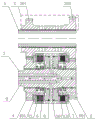
Fig. 1 is a schematic structural view of the present invention;
the labels in the figure are: 1. input shaft, 2, duplicate gear, 201, low gear input gear, 202, high gear input gear, 3, output shaft, 301, clutch hub, 4, low gear driven gear, 401, low gear spline hub, 5, friction disc assembly, 6, piston, 7, return disc spring, 8, high gear driven gear, 801, high gear spline hub, 9, oil gallery.
Detailed Description
As shown in fig. 1, the utility model discloses an automatically controlled double hydraulic pressure formula high-low gear speed change gear, including parallel and interval distribution's input shaft 1 and output shaft 3. A double gear 2 is provided on the input shaft 1 by a spline, and the double gear 2 includes a high-speed input gear 202 and a low-speed input gear 201. The input shaft 1 is provided with a high-gear driven gear 8 and a low-gear driven gear 4 which can rotate through needle bearings, the high-gear input gear 202 is meshed with the high-gear driven gear 8, and the low-gear input gear 201 is meshed with the low-gear driven gear 4. A clutch is also provided on the output shaft 3 for controlling engagement or disengagement between the high-range driven gear 8 and the low-range driven gear 4 and the output shaft 3, thereby achieving high-range or low-range output of the output shaft 3.
Specifically, the utility model discloses a clutch includes clutch hub 301, low gear spline hub 401, high gear spline hub 801, friction disc subassembly 5, piston 6 and return dish spring 7.
The clutch hub 301 includes a ring plate concentrically fixed on the output shaft 3 and a hoop distributed at the outer edge of the ring plate, the ring plate is located at the center of the hoop and divides the hoop into two parts, so that the left side of the hoop corresponds to the low-gear clutch CL and the right side corresponds to the high-gear clutch CH. The low-gear spline hub 401 and the low-gear driven gear 4 are integrally formed and distributed on one side, facing the ring plate, of the low-gear driven gear 4; the high-gear spline hub 801 is integrally formed with the high-gear driven gear 8 and is distributed on the side of the high-gear driven gear 8 facing the ring plate. In fig. 1, the friction plate members 5 are provided between the band-side left side and the low-speed spline hub 401 and between the band right side and the high-speed spline hub 801, respectively. The outer edge of the friction plate assembly 5 is engaged with the inner edge of the band by spline engagement, the inner edge is engaged with the outer edge of the corresponding low-speed spline hub 401 or high-speed spline hub 801 by spline engagement, and the friction plate assembly 5 can engage the clutch hub 301 with the corresponding low-speed spline hub 401 or high-speed spline hub 801 by the pressing action of the piston 6 driven by hydraulic pressure, and separate the clutch hub 301 from the corresponding low-speed spline hub 401 or high-speed spline hub 801 by the return disc spring 7 after the pressing action of the piston 6 disappears.
The number of the pistons 6 is two, and the two pistons 6 are respectively arranged on the output shaft 3 in a sliding manner and positioned on two sides of the ring plate. A first sealing ring is arranged between the inner edge of the piston 6 and the output shaft 3, and a second sealing ring is arranged between the outer edge of the piston 6 and the inner edge of the hub ring, so that sealing cavities are respectively formed between the two sides of the ring plate and the corresponding piston 6, and the two sealing cavities are mutually independent and different and are communicated with two different oil passages 9 arranged in the output shaft 3. The number of the return disc springs 7 is two, and the two return disc springs 7 are respectively sleeved at the position, on the output shaft 3, of one side, back to the annular plate, of the piston 6.
The utility model adopts the hydraulic oil compressing mode, when the low-gear pressure oil duct 9 is filled with oil, the low-gear driven gear 4, the clutch hub 301, the left piston 6 and the output shaft 3 are integrated, and the low-gear clutch CL is jointed; when the high-gear pressure oil port is filled with oil, the high-gear driven gear 8, the clutch hub 301, the right piston 6 and the output shaft 3 are integrated, and the high-gear clutch CH is engaged; at the same time, only one oil passage 9 can be ensured to be filled with oil in an electric control mode, one clutch can be ensured to be engaged, and two clutches cannot be engaged at the same time. The above electric control oil feeding mode is the prior art and is not described again.
The implementation mode of the high gear is as follows: power passes through input shaft 1 input, transmit to duplicate gear 2 through the spline on the input shaft 1, when the high-gear clutch CH who gives the right side leads to pressure oil, pressure oil is full of the right side seal chamber, pressure oil promotes right side piston 6 and moves to the right, make and compress tightly completely between right side friction disc subassembly 5, make high-gear driven gear 8, right side friction disc subassembly 5, clutch hub 301, right side piston 6 becomes an organic whole, power passes through high-gear input gear 202 and transmits to high-gear spline hub 801 through high-gear driven gear 8, internal spline through right side friction disc subassembly 5 transmits power to clutch hub 301, and then transmit power away through output shaft 3. At this time, no pressure oil is supplied to the left clutch CL, the left piston 6 is in the initial position, the power of the input shaft 1 can drive the low-gear driven gear 4 to idle on the output shaft 3 through the low-gear input gear 201, a gap is reserved between the left friction plate assemblies 5, the low-gear spline hub 401 drives part of the left friction plate assembly 5 to rotate, the clutch hub 301 drives part of the left friction plate assembly 5 to rotate, different rotating speeds exist between the inside and the outside of the left friction plate assembly 5, and the low-gear clutch CL does not transmit power.
The low gear implementation is opposite to the high gear implementation and will not be described in detail.
Switching between high and low gears: when the high gear is switched to the low gear, the oil is cut off from the pressure oil of the high gear clutch CH in an electric control mode, meanwhile, the oil is cut on the low gear clutch CL, the high gear clutch CH is disconnected, and the low gear clutch CL is connected; the right return disc spring 7 is reset, the right piston 6 is reset, and the right friction plate assembly 5 is separated; the left piston 6 acts, the left return disc spring 7 compresses, the left friction plate assembly 5 compresses tightly, and power is transmitted to the next stage through the left friction plate assembly 5.
Claims (5)
1. The utility model provides an automatically controlled double hydraulic pressure formula high-low gear speed change gear, includes input shaft (1) and output shaft (3), its characterized in that: a high-gear input gear (202) and a low-gear input gear (201) are fixedly arranged on the input shaft (1), a high-gear driven gear (8) and a low-gear driven gear (4) are rotatably arranged on the output shaft (3), the high-gear input gear (202) is meshed and matched with the high-gear driven gear (8), the low-gear input gear (201) is meshed and matched with the low-gear driven gear (4), and a clutch is further arranged on the output shaft (3) and used for controlling the connection or the separation between the high-gear driven gear (8) and the low-gear driven gear (4) and the output shaft (3);
the clutch comprises a clutch hub (301), a low-gear spline hub (401), a high-gear spline hub (801), a friction plate assembly (5), a piston (6) and a return disc spring (7), wherein the clutch hub (301) is fixed with an output shaft (3), the low-gear spline hub (401) is fixed with a low-gear driven gear (4), the high-gear spline hub (801) is fixed with a high-gear driven gear (8), the friction plate assembly (5) is arranged between the clutch hub (301) and the low-gear spline hub (401) and between the clutch hub (301) and the high-gear spline hub (801), the outer edge of the friction plate assembly (5) is engaged and matched with the clutch hub (301), the inner edge of the friction plate assembly is engaged and matched with the low-gear spline hub (401) or the high-gear spline hub (801) at the corresponding position, and the clutch hub (301) and the corresponding low-gear spline hub (401) or high-gear spline hub (801) can be engaged and matched through the friction plate assembly (5) under the squeezing action of the, and after the squeezing action of the piston (6) disappears, the clutch hub (301) is separated from the corresponding low-gear spline hub (401) or high-gear spline hub (801) through the return disc spring (7).
2. An electrically controlled dual hydraulic high-low gear shifting device according to claim 1, wherein: the high-gear input gear (202) and the low-gear input gear (201) form a duplicate gear (2), and the duplicate gear (2) is connected with the input shaft (1) through a spline.
3. An electrically controlled dual hydraulic high-low gear shifting device according to claim 1, wherein: the clutch hub (301) comprises a ring plate fixed on the output shaft (3) and positioned between the low-gear driven gear (4) and the high-gear driven gear (8), and a hub ring fixed at the outer peripheral position of the ring plate; the low-gear spline hub (401) is fixed on one side, facing the ring plate, of the low-gear driven gear (4), the high-gear spline hub (801) is fixed on one side, facing the ring plate, of the high-gear driven gear (8), the inner edge of the friction plate assembly (5) is connected with the low-gear spline hub (401) or the high-gear spline hub (801) in the corresponding position through splines, and the outer edge of the friction plate assembly (5) is connected with the inner edge of the hub ring through the splines.
4. An electrically controlled dual hydraulic high-low gear shifting device according to claim 3, wherein: the output shaft (3) is provided with pistons (6) which are respectively arranged at the two sides of the ring plate in a sliding manner and are matched with the friction plate assemblies (5) at the corresponding sides, a first sealing ring is arranged between the inner edge of the piston (6) and the output shaft (3), a second sealing ring is arranged between the outer edge of the piston (6) and the inner edge of the hub ring, sealing cavities are respectively formed between the two sides of the ring plate and the corresponding pistons (6), and the output shaft (3) is provided with an oil duct (9) which is correspondingly communicated with the two sealing cavities.
5. An electrically controlled dual hydraulic high-low gear shifting device according to claim 3, wherein: the return disc spring (7) is sleeved on one side, opposite to the ring plate, of any piston (6) on the output shaft (3).
Priority Applications (1)
| Application Number | Priority Date | Filing Date | Title |
|---|---|---|---|
| CN202020557081.6U CN212177713U (en) | 2020-04-15 | 2020-04-15 | Electric control double-hydraulic high-low gear speed change device |
Applications Claiming Priority (1)
| Application Number | Priority Date | Filing Date | Title |
|---|---|---|---|
| CN202020557081.6U CN212177713U (en) | 2020-04-15 | 2020-04-15 | Electric control double-hydraulic high-low gear speed change device |
Publications (1)
| Publication Number | Publication Date |
|---|---|
| CN212177713U true CN212177713U (en) | 2020-12-18 |
Family
ID=73768891
Family Applications (1)
| Application Number | Title | Priority Date | Filing Date |
|---|---|---|---|
| CN202020557081.6U Active CN212177713U (en) | 2020-04-15 | 2020-04-15 | Electric control double-hydraulic high-low gear speed change device |
Country Status (1)
| Country | Link |
|---|---|
| CN (1) | CN212177713U (en) |
Cited By (2)
| Publication number | Priority date | Publication date | Assignee | Title |
|---|---|---|---|---|
| CN114294415A (en) * | 2022-01-06 | 2022-04-08 | 银川威力传动技术股份有限公司 | Double-clutch two-gear speed change device with locking mechanism |
| WO2023092589A1 (en) * | 2021-11-29 | 2023-06-01 | 舍弗勒技术股份两合公司 | Transmission mechanism |
-
2020
- 2020-04-15 CN CN202020557081.6U patent/CN212177713U/en active Active
Cited By (3)
| Publication number | Priority date | Publication date | Assignee | Title |
|---|---|---|---|---|
| WO2023092589A1 (en) * | 2021-11-29 | 2023-06-01 | 舍弗勒技术股份两合公司 | Transmission mechanism |
| CN117897567A (en) * | 2021-11-29 | 2024-04-16 | 舍弗勒技术股份两合公司 | A transmission mechanism |
| CN114294415A (en) * | 2022-01-06 | 2022-04-08 | 银川威力传动技术股份有限公司 | Double-clutch two-gear speed change device with locking mechanism |
Similar Documents
| Publication | Publication Date | Title |
|---|---|---|
| CN107355518B (en) | Transmission for hydraulically driven wheel excavators | |
| CN104896032A (en) | A novel tractor implement power reduction gearbox | |
| CN105485262A (en) | Two-gear transmission for electric vehicle | |
| CN102966706A (en) | Three-shaft double-clutch speed changer | |
| CN201530313U (en) | Power output transmission mechanism for speed changing box of tractor | |
| CN208669966U (en) | Bringing onto load manual transmission | |
| CN105508544A (en) | Combined harvester hydraulic power gearshift transmission case | |
| CN201027947Y (en) | Shaft-lowering output type hydraulic transmission gearbox for tractor | |
| CN201884506U (en) | Tractor load reversing clutch device | |
| CN211951345U (en) | A Two-speed AMT Transmission Without Power Interruption | |
| CN220523128U (en) | Transmission device for power reversing of tractor | |
| CN209164501U (en) | Electronic automobile-used two-gear automatic speed changing case | |
| CN203770571U (en) | Pneumatic-control two-planetary-gear brake clutch | |
| CN103899728B (en) | A kind of Pneumatic-control type dual planetary gear brake coupling | |
| CN115264009B (en) | A two-speed automatic transmission | |
| CN217874011U (en) | 18+9 gear variable speed transmission system and tractor | |
| CN217177226U (en) | Parallel hydraulic retarder capable of automatically clutching | |
| CN209743563U (en) | PTO gearbox for crawler tractor | |
| CN204762244U (en) | Crops combine second gear transmission assembly | |
| CN206054664U (en) | The automobile-used flexible connection variator of 3 3.5T diesel tractions | |
| CN217227295U (en) | With hydraulic drive transmission | |
| CN117565653A (en) | Hybrid power transmission device for high-horsepower tractor | |
| CN213145242U (en) | Integrated two-gear speed change drive axle mechanism for electrified automobile | |
| CN205605758U (en) | Combine hydraulic power gearbox of shifting | |
| CN210461462U (en) | Vehicle main clutch system and vehicle |
Legal Events
| Date | Code | Title | Description |
|---|---|---|---|
| GR01 | Patent grant | ||
| GR01 | Patent grant |