CN212176477U - But height-adjusting's stable form engineering construction scaffold - Google Patents
But height-adjusting's stable form engineering construction scaffold Download PDFInfo
- Publication number
- CN212176477U CN212176477U CN202020178766.XU CN202020178766U CN212176477U CN 212176477 U CN212176477 U CN 212176477U CN 202020178766 U CN202020178766 U CN 202020178766U CN 212176477 U CN212176477 U CN 212176477U
- Authority
- CN
- China
- Prior art keywords
- sliding
- sliding frame
- frame
- fixedly connected
- adjustable height
- Prior art date
- Legal status (The legal status is an assumption and is not a legal conclusion. Google has not performed a legal analysis and makes no representation as to the accuracy of the status listed.)
- Active
Links
Images


Abstract
The utility model discloses a stable type engineering construction scaffold with adjustable height, which comprises a base, wherein a first sliding frame is fixedly arranged on the surface of the base, a second sliding frame is arranged above the first sliding frame, a second sliding frame is arranged between the first sliding frame and the second sliding frame, and rotating shafts are arranged between the first sliding frame and the second sliding frame, the utility model discloses a lifting scaffold is realized by driving a servo motor to extend two expansion brackets, and the stability of the second sliding frame in the lifting process is ensured by rotating a rotating handle to lift a support plate to support the sliding frames, stabilizing the second sliding frame, supporting two boxes with determined intervals through a screw rod to ensure that a top plate is not easy to shake, so as to ensure the normal working environment and life safety of constructors.
Description
Technical Field
The utility model relates to a scaffold specifically is a stable form engineering construction scaffold of adjustable height.
Background
The engineering building is a temporary building tool which is built by building materials, is used for all engineering facilities in the aspects of production, life and environmental management, is also called a scaffold, and is erected for workers to operate and solve vertical and horizontal transportation on a construction site. The high-rise building block is mainly used in places where external walls, interior decoration or high floor height cannot be directly constructed, and is mainly used for up-and-down dry work of constructors, maintenance of peripheral safety nets, high-altitude installation of components and the like.
The construction frame has been extensively deep use in the construction field of building construction, however, current construction frame is inconvenient height-adjusting, and when height-adjusting, because the support body is too high, constructor stands on the support body, causes the support body to rock easily, seriously influences constructor's operational environment and safety. Accordingly, one skilled in the art provides a stable type construction scaffold with adjustable height to solve the problems suggested in the background art.
Disclosure of Invention
An object of the utility model is to provide a but height-adjusting's stable form engineering construction scaffold to solve the problem that proposes in the above-mentioned background art.
In order to achieve the above object, the utility model provides a following technical scheme:
a stable type engineering construction scaffold with adjustable height comprises a base, wherein a first sliding frame is fixedly arranged on the surface of the base, another first sliding frame is arranged above the first sliding frame, a second sliding frame is arranged between the two first sliding frames, a rotating shaft is arranged between the two first sliding frames and the second sliding frame, telescopic frames are arranged on the periphery sides of the front end and the rear end of the rotating shaft, and pulleys are rotatably connected to the four tail ends of the telescopic frames;
the front side and the rear side of the second sliding frame are both rotatably connected with two worms, the two worms are fixedly connected, the thread winding directions are opposite, gears meshed with the two worms are arranged on the upper sides and the lower sides of the two worms, one ends of the front side and the rear side of the second sliding frame are both fixedly provided with a first servo motor, a motor shaft of the first servo motor is fixedly connected with one end of a worm, a top plate is fixedly connected to the surface of the first sliding frame on the upper side, and four corners of the top plate are both in threaded connection with a first screw;
the equal fixed mounting in base surface four corners has the slip post, No. two slip frame sliding connection is between a plurality of slip posts, and all seted up the dead slot in a plurality of slip posts, the dead slot internal rotation is connected with screw rod two, the threaded connection of two week sides of screw rod has to support the board, support board sliding connection just to support the below that the board is located No. two slip frames in the dead slot, two lower extreme fixedly connected with bevel gear two of screw rod, two front sides of bevel gear are provided with bevel gear one rather than the meshing, bevel gear one rotates to be connected inside the slip post, and bevel gear one fixedly connected with is located the outside twist grip of slip post.
As a further aspect of the present invention: two sliding grooves corresponding to the pulleys are formed in the front inner side and the rear inner side of the first sliding frame and the second sliding frame, and the pulleys are connected in the sliding grooves in a sliding mode.
As a further aspect of the present invention: and the gears are respectively and fixedly connected to the outer sides of the pulleys sliding in the second sliding frame inner sliding grooves.
As a further aspect of the present invention: the top plate surface edge is equipped with the railing, and railing upper end fixed mounting has a fence frame, and the equal fixed mounting in fence frame surface four corners has servo motor two.
As a further aspect of the present invention: the upper end of the first screw rod is fixedly connected with a telescopic rod, the upper end of the telescopic rod is fixedly connected with a motor shaft of the second servo motor, and the lower end of the first screw rod is fixedly connected with a pad foot.
As a further aspect of the present invention: the base bottom surface four corners department all fixed mounting have the universal wheel, is equipped with the rotation piece in the universal wheel.
As a further aspect of the present invention: and the controller is respectively and electrically connected with the first servo motor and the second servo motors.
Compared with the prior art, the beneficial effects of the utility model are that:
1. the utility model discloses a drive servo motor makes two expansion brackets extend to reach the purpose of lift scaffold, convenient and fast, simultaneously for solving because the scaffold rises the problem of rocking easily that leads to too high, set up the slip post on the base very much, guarantee No. two slip frames and in the stability of the in-process that rises, rotate the turning handle and make to the board rise and support the slip frame, stabilize No. two slip frames.
2. The utility model discloses a guarantee the holistic stability of scaffold, through establishing screw rod one that can stretch out and draw back between upper sliding frame and No. two sliding frame, will confirm to support through screw rod one between two casees of spaced, guarantee that the roof is difficult for rocking to guarantee constructor's normal operational environment and life safety.
Drawings
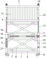
Fig. 1 is a schematic structural view of a stable type engineering construction scaffold with adjustable height.
Fig. 2 is a side view of a stable type construction scaffold with adjustable height.
Fig. 3 is an enlarged view of fig. 1A of a height adjustable stable construction scaffold.
In the figure: 1. a base; 2. a first sliding frame; 3. a second sliding frame; 4. a top plate; 5. a hurdle frame; 6. a telescopic frame; 7. a pulley; 8. a rotating shaft; 9. a universal wheel; 10. a handle is rotated; 11. a controller; 12. a resisting plate; 13. a first screw rod; 14. a first servo motor; 15. a telescopic rod; 16. a servo motor II; 17. a railing; 18. a foot pad; 19. a gear; 20. a worm; 21. a sliding post; 22. a first bevel gear; 23. a second bevel gear; 24. and a second screw.
Detailed Description
The technical solutions in the embodiments of the present invention will be described clearly and completely with reference to the accompanying drawings in the embodiments of the present invention, and it is obvious that the described embodiments are only some embodiments of the present invention, not all embodiments. Based on the embodiments in the present invention, all other embodiments obtained by a person skilled in the art without creative work belong to the protection scope of the present invention.
Referring to fig. 1 to 3, in an embodiment of the present invention, a stable type engineering construction scaffold with adjustable height includes a base 1, a first sliding frame 2 is fixedly installed on a surface of the base 1, another first sliding frame 2 is arranged above the first sliding frame 2, a second sliding frame 3 is arranged between the first sliding frames 2, a rotating shaft 8 is arranged between the first sliding frames 2 and the second sliding frame 3, telescopic frames 6 are arranged on the circumferential sides of the front and rear ends of the rotating shaft 8, four ends of the telescopic frames 6 are rotatably connected with pulleys 7, sliding grooves corresponding to the pulleys 7 are arranged on the front and rear inner sides of the first sliding frames 2 and the second sliding frames 3, and the pulleys 7 are slidably connected in the sliding grooves;
two worms 20 are rotatably connected to the front side and the rear side of the second sliding frame 3, the two worms 20 are fixedly connected, the thread winding directions are opposite, gears 19 meshed with the worms are arranged on the upper side and the lower side of the two worms 20, the gears 19 are respectively fixedly connected to the outer sides of the pulleys 7 sliding in the sliding groove of the second sliding frame 3, one ends of the front side and the rear side of the second sliding frame 3 are fixedly provided with a first servo motor 14, a motor shaft of the first servo motor 14 is fixedly connected with one end of the worm 20, the surface of the first sliding frame 2 on the upper side is fixedly connected with a top plate 4, the first servo motor 14 enables the two worms 20 to rotate, the two worms 20 drive the left and right gears 19 meshed with the worms to approach each other, the pulleys 7 connected with the tail ends of the telescopic frames 6 move in the sliding grooves in the two sliding frames, the upper and lower telescopic frames 6 extend upwards to lift the top plate, the edge of the surface of the top plate 4 is provided with a railing 17, the upper end of the railing 17 is fixedly provided with a railing frame 5, four corners of the surface of the railing frame 5 are fixedly provided with a second servo motor 16, the upper end of a first screw rod 13 is fixedly connected with an expansion link 15, the upper end of the expansion link 15 is fixedly connected with a motor shaft of the second servo motor 16, the lower end of the first screw rod 13 is fixedly connected with a pad foot 18, the second servo motors 16 work, the first screw rod 13 is rotated through the expansion link 15, and the first screw rod 13 slowly descends to abut against a sliding column 21 due to the threaded connection effect of the first screw rod 13 and the top plate 4;
four corners of the surface of the base 1 are fixedly provided with sliding columns 21, a second sliding frame 3 is connected between the sliding columns 21 in a sliding manner, hollow grooves are formed in the sliding columns 21, a second screw 24 is connected in the hollow grooves in a rotating manner, a resisting plate 12 is connected to the peripheral side of the second screw 24 in a threaded manner, the resisting plate 12 is connected in the hollow grooves in a sliding manner and is positioned below the second sliding frame 3, the lower end of the second screw 24 is fixedly connected with a second bevel gear 23, the front side of the second bevel gear 23 is provided with a first bevel gear 22 meshed with the second bevel gear 22, the first bevel gear 22 is connected in the sliding columns 21 in a rotating manner, the first bevel gear 22 is fixedly connected with a rotating handle 10 positioned outside the sliding columns 21, after the construction height is determined, the rotating handle 10 is rotated, the first bevel gear 22 drives the second screw 24 to rotate through the second bevel gear 23, so that the resisting plate 12 in threaded connection with the second screw 24 is propp, equal fixed mounting in base 1 bottom surface four corners department has universal wheel 9, is equipped with in the universal wheel 9 and rotates the piece, and the scaffold main part passes through universal wheel 9 and removes to the work place, one fixed mounting has controller 11 on the sliding column 21, and controller 11 is respectively in two servo motor 14, two 16 electric connection of a plurality of servo motor.
The utility model discloses a theory of operation is:
when the scaffold is used, a scaffold main body is moved to a working site through a universal wheel 9, a controller 11 controls a first servo motor 14 to work, the first servo motor 14 enables two worms 20 to rotate, the two worms 20 drive a left gear 19 and a right gear 19 which are meshed with the worms to approach each other, a pulley 7 connected with the tail ends of telescopic frames 6 moves in a sliding groove in the two sliding frames, the upper telescopic frame 6 and the lower telescopic frame 6 extend upwards to lift a top plate 4, after the construction height is determined, a rotating handle 10 is rotated, a first bevel gear 22 drives a second screw 24 to rotate through a second bevel gear 23, a resisting plate 12 in threaded connection with the second screw 24 moves up and down on a sliding column 21 until the resisting plate 12 is propped against the bottom surface of the second sliding frame 3, a plurality of second servo motors 16 are controlled to work, the first screw 13 is rotated through a telescopic rod 15, and the first screw 13 slowly descends due to the threaded connection effect of the, the scaffold is pressed against the sliding column 21, so that the scaffold is not easy to shake, and the scaffold is stable at the moment.
The above, only be the concrete implementation of the preferred embodiment of the present invention, but the protection scope of the present invention is not limited thereto, and any person skilled in the art is in the technical scope of the present invention, according to the technical solution of the present invention and the utility model, the concept of which is equivalent to replace or change, should be covered within the protection scope of the present invention.
Claims (7)
1. A stable type engineering construction scaffold with adjustable height comprises a base (1) and is characterized in that a first sliding frame (2) is fixedly mounted on the surface of the base (1), another first sliding frame (2) is arranged above the first sliding frame (2), a second sliding frame (3) is arranged between the two first sliding frames (2), rotating shafts (8) are arranged between the two first sliding frames (2) and the second sliding frame (3), telescopic frames (6) are arranged on the periphery sides of the front end and the rear end of each rotating shaft (8), and pulleys (7) are rotatably connected to the four tail ends of each telescopic frame (6);
the front side and the rear side of the second sliding frame (3) are both rotatably connected with two worms (20), the two worms (20) are fixedly connected, the thread winding directions are opposite, gears (19) meshed with the two worms (20) are arranged on the upper side and the lower side of the two worms (20), one ends of the front side and the rear side of the second sliding frame (3) are both fixedly provided with a first servo motor (14), a motor shaft of the first servo motor (14) is fixedly connected with one end of the worm (20), the surface of the first sliding frame (2) on the upper side is fixedly connected with a top plate (4), and four corners of the top plate (4) are both in threaded connection with a first screw (;
the sliding columns (21) are fixedly mounted at four corners of the surface of the base (1), the second sliding frame (3) is connected between the plurality of sliding columns (21) in a sliding mode, empty grooves are formed in the plurality of sliding columns (21), a second screw rod (24) is connected in the empty grooves in a rotating mode, a supporting plate (12) is connected to the peripheral side of the second screw rod (24) in a threaded mode, the supporting plate (12) is connected in the empty grooves in a sliding mode, the supporting plate (12) is located below the second sliding frame (3), a second bevel gear (23) is fixedly connected to the lower end of the second screw rod (24), a first bevel gear (22) meshed with the second bevel gear is arranged on the front side of the second bevel gear (23), the first bevel gear (22) is connected to the inside of the sliding columns (21) in a rotating mode, and the first bevel.
2. The stable type engineering and construction scaffold with adjustable height as claimed in claim 1, wherein the inner sides of the first sliding frame (2) and the second sliding frame (3) are provided with sliding grooves corresponding to the sliding wheels (7), and the sliding wheels (7) are slidably connected in the sliding grooves.
3. The stable type construction frame with adjustable height of claim 1, wherein a plurality of gears (19) are fixedly connected to the outer side of the pulley (7) sliding in the sliding groove of the second sliding frame (3).
4. The stable type engineering construction scaffold with adjustable height of claim 1, wherein a rail (17) is arranged on the surface edge of the top plate (4), a frame (5) is fixedly installed on the upper end of the rail (17), and two servo motors (16) are fixedly installed on four corners of the surface of the frame (5).
5. The stable type engineering and construction scaffold with adjustable height as claimed in claim 1, wherein the upper end of the first screw (13) is fixedly connected with a telescopic rod (15), the upper end of the telescopic rod (15) is fixedly connected with the motor shaft of the second servo motor (16), and the lower end of the first screw (13) is fixedly connected with a foot pad (18).
6. The stable type engineering and construction scaffold with adjustable height as claimed in claim 1, wherein the universal wheels (9) are fixedly installed at four corners of the bottom surface of the base (1), and rotating members are installed in the universal wheels (9).
7. The stable type engineering and construction scaffold with adjustable height as claimed in claim 1, wherein a controller (11) is fixedly installed on one of said sliding columns (21), and the controller (11) is electrically connected to two servo motors one (14) and a plurality of servo motors two (16), respectively.
Priority Applications (1)
| Application Number | Priority Date | Filing Date | Title |
|---|---|---|---|
| CN202020178766.XU CN212176477U (en) | 2020-02-18 | 2020-02-18 | But height-adjusting's stable form engineering construction scaffold |
Applications Claiming Priority (1)
| Application Number | Priority Date | Filing Date | Title |
|---|---|---|---|
| CN202020178766.XU CN212176477U (en) | 2020-02-18 | 2020-02-18 | But height-adjusting's stable form engineering construction scaffold |
Publications (1)
| Publication Number | Publication Date |
|---|---|
| CN212176477U true CN212176477U (en) | 2020-12-18 |
Family
ID=73773384
Family Applications (1)
| Application Number | Title | Priority Date | Filing Date |
|---|---|---|---|
| CN202020178766.XU Active CN212176477U (en) | 2020-02-18 | 2020-02-18 | But height-adjusting's stable form engineering construction scaffold |
Country Status (1)
| Country | Link |
|---|---|
| CN (1) | CN212176477U (en) |
Cited By (1)
| Publication number | Priority date | Publication date | Assignee | Title |
|---|---|---|---|---|
| CN113006443A (en) * | 2021-02-24 | 2021-06-22 | 济南市基仁建安有限公司 | Improved generation construction frame |
-
2020
- 2020-02-18 CN CN202020178766.XU patent/CN212176477U/en active Active
Cited By (1)
| Publication number | Priority date | Publication date | Assignee | Title |
|---|---|---|---|---|
| CN113006443A (en) * | 2021-02-24 | 2021-06-22 | 济南市基仁建安有限公司 | Improved generation construction frame |
Similar Documents
| Publication | Publication Date | Title |
|---|---|---|
| CN210736136U (en) | Elevating platform is used in communication equipment maintenance | |
| CN212176477U (en) | But height-adjusting's stable form engineering construction scaffold | |
| CN214656426U (en) | Bridge construction platform | |
| CN214272856U (en) | A adjustable scaffold frame for interior decoration | |
| CN212295575U (en) | Safe type scaffold frame for construction | |
| CN206144163U (en) | A slip dolly that is used for wall body to print machine people | |
| CN207633732U (en) | A kind of scaffold of architectural engineering | |
| CN112096037B (en) | Scaffold frame that can safe location construction | |
| CN114541722B (en) | Scaffold frame for building construction of adjustable height | |
| CN215803036U (en) | Liftable scaffold for building construction | |
| CN215558426U (en) | Liftable support for construction engineering construction | |
| CN212984562U (en) | Mobilizable safe civil engineering scaffold | |
| CN215107567U (en) | Safe anti-falling device for building construction | |
| CN212639887U (en) | Elevator for indoor decoration | |
| CN212248943U (en) | Support tool for construction of green building energy-saving roof | |
| CN217924715U (en) | Scaffold for building | |
| CN218205569U (en) | Construction scaffold | |
| CN212201213U (en) | Novel scaffold for building installation | |
| CN212836583U (en) | Novel scaffold for decoration | |
| CN211007567U (en) | Novel civil engineering is with scaffold frame of ascending a height | |
| CN216305321U (en) | Indoor scaffold for architectural decoration | |
| CN217734771U (en) | Building engineering construction climbing device | |
| CN211313283U (en) | Building platform for outdoor building and indoor decoration | |
| CN217054503U (en) | Concatenation formula container board house | |
| CN215564312U (en) | Interval-adjustable scaffold for construction engineering |
Legal Events
| Date | Code | Title | Description |
|---|---|---|---|
| GR01 | Patent grant | ||
| GR01 | Patent grant | ||
| TR01 | Transfer of patent right | ||
| TR01 | Transfer of patent right |
Effective date of registration: 20221014 Address after: 475000 West House, Floor 25, East Unit, Building 1, Juxiangli, 14th Street, Kaifeng District, Henan Pilot Free Trade Zone, Kaifeng City, Henan Province Patentee after: Henan Huaitian Construction Engineering Co.,Ltd. Address before: 614000 No. 12-1, Baoma street, Shizhong District, Leshan City, Sichuan Province Patentee before: Wang Yuanzhong |