CN212170646U - Automatic positioning and punching tool for automobile bumper - Google Patents
Automatic positioning and punching tool for automobile bumper Download PDFInfo
- Publication number
- CN212170646U CN212170646U CN202020968839.5U CN202020968839U CN212170646U CN 212170646 U CN212170646 U CN 212170646U CN 202020968839 U CN202020968839 U CN 202020968839U CN 212170646 U CN212170646 U CN 212170646U
- Authority
- CN
- China
- Prior art keywords
- fixedly connected
- automatic positioning
- automobile bumper
- punching tool
- punching
- Prior art date
- Legal status (The legal status is an assumption and is not a legal conclusion. Google has not performed a legal analysis and makes no representation as to the accuracy of the status listed.)
- Expired - Fee Related
Links
- 238000004080 punching Methods 0.000 title claims abstract description 34
- 230000002457 bidirectional effect Effects 0.000 claims description 4
- 239000002699 waste material Substances 0.000 abstract description 4
- 238000006073 displacement reaction Methods 0.000 description 2
- 229920003023 plastic Polymers 0.000 description 2
- 239000004033 plastic Substances 0.000 description 2
- 230000009286 beneficial effect Effects 0.000 description 1
- 238000005034 decoration Methods 0.000 description 1
- 229920006351 engineering plastic Polymers 0.000 description 1
- 238000004519 manufacturing process Methods 0.000 description 1
- 239000000463 material Substances 0.000 description 1
Images


Landscapes
- Perforating, Stamping-Out Or Severing By Means Other Than Cutting (AREA)
Abstract
The utility model discloses an automatic positioning and punching tool for automobile bumpers, which comprises a fixed box, wherein the top part of the fixed box is fixedly connected with a top plate through a support rod, the center of the bottom part of the top plate is fixedly connected with a connecting frame through two telescopic rods, the inner surface of the connecting frame is fixedly connected with a punching motor, the output end of the punching motor is fixedly connected with a punching head, the top part of the fixed box is provided with a processing groove, the left side and the right side of the inner surface of the processing groove are both provided with chutes, the inner surfaces of the two chutes are both slidably connected with a slide rod, and the top ends of the two slide rods are both fixedly connected with a first clamping plate, the utility model can drive two first clamping plates to clamp workpieces left and right through the cooperation between the two-way telescopic rods, the connecting block and the slide rod, and can, the accurate positioning is automatically realized, and the operation is convenient; the blanking box is matched to collect punched waste, so that the working efficiency is improved.
Description
Technical Field
The utility model relates to an automobile bumper technical field specifically is an automobile bumper automatic positioning instrument of punching.
Background
The front end and the rear end of the automobile are provided with bumpers which not only have the decoration function, but also are more important to be safety devices which absorb and buffer the external impact force and protect the automobile body and passengers. With the development of the automobile industry and the extensive use of engineering plastics in the automobile industry, automobile bumpers have also been revolutionized as an important safety device. At present, the front and rear bumpers of the automobile not only keep the original protection function, but also pursue harmony and unity with the shape of the automobile body and pursue the light weight of the automobile. The front and rear bumpers of a car are all made of plastic and are called plastic bumpers.
The processing of car bumper needs punch it to the position that car bumper punched needs the comparison of control accurate, needs fix a position its position through the manual work, then presss from both sides tightly, but adjusts its position through the manual work, and the error can appear in inevitable, makes the position of punching take place skew easily, for this the utility model provides a car bumper automatic positioning instrument of punching.
SUMMERY OF THE UTILITY MODEL
An object of the utility model is to provide an automobile bumper automatic positioning instrument of punching to solve the problem that proposes among the above-mentioned background art.
In order to achieve the above object, the utility model provides a following technical scheme:
the utility model provides an automobile bumper automatic positioning instrument of punching, includes the fixed case, branch fixedly connected with roof is passed through at the fixed roof portion, the center of roof bottom is through two telescopic link fixedly connected with links, the internal surface fixedly connected with punching motor of link, punching motor's output fixedly connected with punching head, the processing groove has been seted up at the top of fixed case, the spout has all been seted up, two to the left and right sides of processing inslot internal surface the equal sliding connection in internal surface of spout has a slide bar, two the first splint of the equal fixedly connected with in top of slide bar.
As a further aspect of the present invention: the inside of fixed case has seted up the fixed slot, the inside of fixed slot is through fixed block fixedly connected with bidirectional expansion pole.
As a further aspect of the present invention: the equal fixedly connected with connecting block in both ends about two-way telescopic link, two the top of connecting block respectively with the bottom fixed connection of two slide bars.
As a further aspect of the present invention: the equal fixedly connected with support frame in the left and right sides of processing inslot surface, the standing groove has been seted up to the inside of support frame.
As a further aspect of the present invention: the equal sliding connection in both sides has the movable rod, two around the standing groove internal surface the equal fixedly connected with second splint in one side that the movable rod is relative, the surface cover of movable rod is equipped with the spring.
As a further aspect of the present invention: and a blanking box is fixedly arranged at the bottom of the inner cavity of the processing tank.
As a further aspect of the present invention: the equal fixedly connected with connecting rod in the left and right sides at fixed slot inner chamber top, two the equal fixedly connected with sliding sleeve in bottom of connecting rod, the internal surface of sliding sleeve and the surface sliding connection of telescopic link.
Compared with the prior art, the beneficial effects of the utility model are that: the utility model can drive the two first clamping plates to clamp the workpiece left and right through the cooperation between the two-way telescopic rod, the connecting block and the sliding rod, and can drive the two second clamping plates to clamp the workpiece front and back through the cooperation between the movable rod and the spring, thereby automatically realizing accurate positioning and convenient operation; the blanking box is matched to collect punched waste, so that the working efficiency is improved.
Drawings
FIG. 1 is a schematic structural view of an automatic positioning and punching tool for a bumper of an automobile.
FIG. 2 is a top view of a tool slot in an automatic bumper positioning and punching tool.
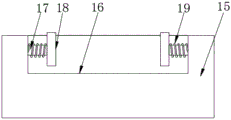
FIG. 3 is a structural side view of a support frame in an automatic positioning and punching tool for a bumper of an automobile.
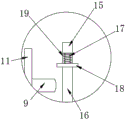
FIG. 4 is an enlarged view of a portion of the automatic positioning and punching tool for a bumper shown in FIG. 2.
In the figure: 1. a fixed box; 2. a strut; 3. a top plate; 4. a telescopic rod; 5. a connecting frame; 6. a punching motor; 7. punching a hole head; 8. processing a tank; 9. a chute; 10. a slide bar; 11. a first splint; 12. fixing grooves; 13. a fixed block; 14. connecting blocks; 15. a support frame; 16. a placement groove; 17. a movable rod; 18. a second splint; 19. a spring; 20. blanking the material box; 21. a connecting rod; 22. a sliding sleeve; 23. two-way telescopic link.
Detailed Description
The technical solution of the present patent will be described in further detail with reference to the following embodiments.
Referring to fig. 1-4, an automatic positioning and punching tool for automobile bumpers comprises a fixed box 1, wherein a fixed groove 12 is formed in the fixed box 1, connecting rods 21 are fixedly connected to the left side and the right side of the top of an inner cavity of the fixed groove 12, sliding sleeves 22 are fixedly connected to the bottom ends of the two connecting rods 21, the inner surface of each sliding sleeve 22 is slidably connected to the outer surface of a telescopic rod 4, and a bidirectional telescopic rod 23 is fixedly connected to the inside of the fixed groove 12 through a fixed block 13; the punching waste can be collected by matching with a blanking box 20, the working efficiency is improved, the left end and the right end of a bidirectional telescopic rod 23 are fixedly connected with connecting blocks 14, the tops of the two connecting blocks 14 are respectively and fixedly connected with the bottom ends of two slide bars 10, the top of a fixed box 1 is fixedly connected with a top plate 3 through a support bar 2, the center of the bottom of the top plate 3 is fixedly connected with a connecting frame 5 through two telescopic bars 4, the inner surface of the connecting frame 5 is fixedly connected with a punching motor 6, the output end of the punching motor 6 is fixedly connected with a punching head 7, the top of the fixed box 1 is provided with a processing groove 8, the bottom of the inner cavity of the processing groove 8 is fixedly provided with the blanking box 20, the left side and the right side of the inner surface of the processing groove 8 are both fixedly connected with supporting frames 15, the inside of the supporting frames 15 is provided with a placing groove 16, the, the surface cover of movable rod 17 is equipped with spring 19, and spout 9 has all been seted up to the left and right sides of processing groove 8 internal surface, and the equal sliding connection of internal surface of two spout 9 has slide bar 10, the equal fixedly connected with first splint 11 in top of two slide bars 10.
The utility model discloses a theory of operation is: place the work piece that will need processing in the standing groove 16 at two support frames 15 tops, cooperation movable rod 17 and spring 19 press from both sides tightly the front and back both sides of work piece, restart two-way telescopic rod 23, two-way telescopic rod 23 drives two slide bars 10 through connecting block 14 and carries out the phase displacement, realize two first splint 11 phase displacement, control the work piece and press from both sides tightly, the realization is to the accurate location of advancing of this work piece, it realizes punching to cooperate telescopic rod 4 and grinding motor again, the waste material that the production of punching directly falls at blanking case 20.
In the description of the present invention, it is to be noted that, unless otherwise explicitly specified or limited, the terms "mounted," "connected," and "connected" are to be construed broadly, and may be, for example, fixedly connected, detachably connected, or integrally connected; can be mechanically or electrically connected; they may be connected directly or indirectly through intervening media, or they may be interconnected between two elements. The specific meaning of the above terms in the present invention can be understood by those of ordinary skill in the art through specific situations.
Although the preferred embodiments of the present patent have been described in detail, the present patent is not limited to the above embodiments, and various changes can be made without departing from the spirit of the present patent within the knowledge of those skilled in the art.
Claims (7)
1. The utility model provides an automobile bumper automatic positioning instrument of punching, includes fixed case (1), branch (2) fixedly connected with roof (3) are passed through at fixed case (1) top, a serial communication port, the center of roof (3) bottom is through two telescopic link (4) fixedly connected with link (5), the internal surface fixedly connected with motor (6) that punches of link (5), the output fixedly connected with head (7) that punches of motor (6), processing groove (8) have been seted up at the top of fixed case (1), spout (9), two have all been seted up to the left and right sides of processing groove (8) internal surface the equal sliding connection of internal surface of spout (9) has slide bar (10), two the first splint (11) of the equal fixedly connected with in top of slide bar (10).
2. The automatic positioning and punching tool for the automobile bumper as claimed in claim 1, wherein a fixing groove (12) is formed in the fixing box (1), and a bidirectional telescopic rod (23) is fixedly connected to the inside of the fixing groove (12) through a fixing block (13).
3. The automatic positioning and punching tool for the automobile bumper as claimed in claim 2, wherein the left and right ends of the two-way telescopic rod (23) are fixedly connected with the connecting blocks (14), and the tops of the two connecting blocks (14) are respectively fixedly connected with the bottom ends of the two sliding rods (10).
4. The automatic positioning and punching tool for the automobile bumper according to claim 1, wherein supporting frames (15) are fixedly connected to the left side and the right side of the inner surface of the processing groove (8), and a placing groove (16) is formed in each supporting frame (15).
5. The automatic positioning and punching tool for the automobile bumper according to claim 4, wherein movable rods (17) are slidably connected to the front side and the rear side of the inner surface of the placing groove (16), a second clamping plate (18) is fixedly connected to the opposite side of each of the two movable rods (17), and a spring (19) is sleeved on the outer surface of each movable rod (17).
6. The automatic positioning and punching tool for the automobile bumper as claimed in claim 1, wherein a blanking box (20) is fixedly mounted at the bottom of the inner cavity of the processing tank (8).
7. The automatic positioning and punching tool for the automobile bumper as claimed in claim 2, wherein connecting rods (21) are fixedly connected to the left and right sides of the top of the inner cavity of the fixing groove (12), sliding sleeves (22) are fixedly connected to the bottom ends of the two connecting rods (21), and the inner surfaces of the sliding sleeves (22) are slidably connected with the outer surfaces of the telescopic rods (4).
Priority Applications (1)
| Application Number | Priority Date | Filing Date | Title |
|---|---|---|---|
| CN202020968839.5U CN212170646U (en) | 2020-06-01 | 2020-06-01 | Automatic positioning and punching tool for automobile bumper |
Applications Claiming Priority (1)
| Application Number | Priority Date | Filing Date | Title |
|---|---|---|---|
| CN202020968839.5U CN212170646U (en) | 2020-06-01 | 2020-06-01 | Automatic positioning and punching tool for automobile bumper |
Publications (1)
| Publication Number | Publication Date |
|---|---|
| CN212170646U true CN212170646U (en) | 2020-12-18 |
Family
ID=73788441
Family Applications (1)
| Application Number | Title | Priority Date | Filing Date |
|---|---|---|---|
| CN202020968839.5U Expired - Fee Related CN212170646U (en) | 2020-06-01 | 2020-06-01 | Automatic positioning and punching tool for automobile bumper |
Country Status (1)
| Country | Link |
|---|---|
| CN (1) | CN212170646U (en) |
Cited By (1)
| Publication number | Priority date | Publication date | Assignee | Title |
|---|---|---|---|---|
| CN113001668A (en) * | 2021-02-19 | 2021-06-22 | 浙江大学山东工业技术研究院 | Industrial automation is with drilling equipment |
-
2020
- 2020-06-01 CN CN202020968839.5U patent/CN212170646U/en not_active Expired - Fee Related
Cited By (1)
| Publication number | Priority date | Publication date | Assignee | Title |
|---|---|---|---|---|
| CN113001668A (en) * | 2021-02-19 | 2021-06-22 | 浙江大学山东工业技术研究院 | Industrial automation is with drilling equipment |
Similar Documents
| Publication | Publication Date | Title |
|---|---|---|
| CN215237114U (en) | Stamping device for machining | |
| CN111283062A (en) | A biax feeds punch press for panel dashes array mesh | |
| CN209902015U (en) | Machine-building stamping device | |
| CN215357392U (en) | Anticollision roof beam CNC positioning fixture | |
| CN2421192Y (en) | Synchronous punching special machine for jointing plate | |
| CN214351054U (en) | Mechanical hydraulic clamping mechanism for industrial production | |
| CN218283360U (en) | Automatic stamping equipment combination frock | |
| CN215697243U (en) | Hole pressing machine for machining automobile parts | |
| CN214290494U (en) | A stamping fixture for automobile mold production | |
| CN209969718U (en) | Cutting machine tool for machining tower piece of electric power iron tower | |
| CN211218346U (en) | Universal die carrier for hardware die | |
| CN212144054U (en) | Bending machine convenient for taking out workpiece | |
| CN208437550U (en) | The automatic transmission manipulator of multi-process punching machine punching press | |
| CN224087728U (en) | A stamping device for processing automotive parts | |
| CN213196920U (en) | High-precision cutting and grinding device for die opening | |
| CN217942329U (en) | Battery split shell cover welding positioning mechanism | |
| CN208592766U (en) | A kind of fitting device for automobile front protecting installation | |
| CN216027545U (en) | Die combination device for mechanical design and manufacturing | |
| CN217941569U (en) | Device for punching safety seat by nitrogen spring | |
| CN213969793U (en) | A license plate automatic reed loading device | |
| CN220533486U (en) | Automobile bumper impact welding integrated device | |
| CN218983825U (en) | Quick typesetting shaping tool fixture | |
| CN214603051U (en) | Automatic bending and cutting device for water tank steel plate | |
| CN212239070U (en) | Forging and pressing fixed mounting fixture | |
| CN218939759U (en) | Lithium battery core module tooling mechanism and battery core production system |
Legal Events
| Date | Code | Title | Description |
|---|---|---|---|
| GR01 | Patent grant | ||
| GR01 | Patent grant | ||
| CF01 | Termination of patent right due to non-payment of annual fee | ||
| CF01 | Termination of patent right due to non-payment of annual fee |
Granted publication date: 20201218 |