CN212166883U - Dust remover with shunting dust removal function - Google Patents
Dust remover with shunting dust removal function Download PDFInfo
- Publication number
- CN212166883U CN212166883U CN202020176147.7U CN202020176147U CN212166883U CN 212166883 U CN212166883 U CN 212166883U CN 202020176147 U CN202020176147 U CN 202020176147U CN 212166883 U CN212166883 U CN 212166883U
- Authority
- CN
- China
- Prior art keywords
- water
- dust removal
- dust
- box body
- overflow
- Prior art date
- Legal status (The legal status is an assumption and is not a legal conclusion. Google has not performed a legal analysis and makes no representation as to the accuracy of the status listed.)
- Active
Links
Images


Abstract
The utility model discloses a dust remover for shunting dust removal, which comprises a box body, wherein the bottom of the box body is provided with a sewage outlet, and the upper part of the box body is provided with a dust removing device; an air inlet cavity of the dust removal device is communicated with a waste gas inlet arranged on the box body, the dust removal device comprises an overflow disc for containing water and a plurality of air guide pipes, one end of each air guide pipe is communicated with the air inlet cavity, the other end of each air guide pipe is immersed in the water of the overflow disc, and the bottom of the overflow disc is provided with a plurality of water permeable holes; the upper part of the dust removing device is provided with a plurality of atomized water nozzles; the top of the box body is provided with a purified gas outlet. Through set up the mud discharge of permeating water hole with sedimentary in the overflow dish bottom the overflow dish, simultaneously through setting up moisturizing in dust collector upper portion atomizing water shower nozzle to the overflow dish, make the other end submergence all the time of air duct in aqueous, guarantee going on of exhaust gas dust removal work, this process can alleviate the influence of the mud sediment of aquatic to removing dust to a great extent, water and the waste gas contact in the make full use of overflow dish volume space to reach better dust removal effect.
Description
Technical Field
The utility model belongs to the technical field of environmental protection dust collecting equipment and specifically relates to a wet dust collector that divides the dust removal is carried out to the gas that removes dust.
Background
A wet dust collector is a device which makes dust-contained gas and liquid (generally water) closely contact, utilizes the inertia collision of water drops and particles or utilizes the full mixing action of water and dust and other actions to capture particles or make the particles enlarge or remain in a fixed container to achieve the effect of separating water from dust. The wet dust collector can effectively remove liquid or solid particles with the diameter of 0.1-20 microns from the airflow, and can also remove part of gaseous pollutants. The device has the advantages of simple structure, small occupied area, convenience in operation and maintenance, high purification efficiency and the like, and can treat high-temperature and high-humidity airflow.
The wet dust collector can be applied to various industrial dusts, and is particularly needed to be used in the treatment of dust-containing waste gas containing water vapor.
In order to solve the above problems, chinese utility model patent publication No. CN 208049629U provides an automatic circulation overflow screen pipe immersion type high efficiency wet dust collector, wherein the dust collector comprises a filtering chamber and a dewatering chamber, the filtering chamber comprises a filtering chamber and an overflow type water bath box, the filtering chamber comprises a spraying device and a screen pipe, and a plurality of groups of screen pipes are inserted into the water of the overflow type water bath box; the filter chamber is provided with a dust-containing flue gas inlet; a plurality of layers of respectively closed filter chambers are arranged in the filter bin from top to bottom, the upper part of each layer of the filter chambers is provided with the spray device, the corresponding lower part of each layer of the filter chambers is provided with a sieve tube frame and a plurality of groups of sieve tubes extending downwards, and the side wall of the filter chamber at the upper part of each sieve tube is provided with a dust-containing flue gas inlet; the perforated parts of the sieve tubes of a plurality of groups are inserted into the overflow type water bath water box with an opening below the filtering chamber, and the dust-containing smoke enters the water in the overflow type water bath box through the upper opening of the sieve tube and is discharged into the filtering bin after being filtered; the spraying device of the first layer of the filtering chamber is connected with an upper water pipeline, and the other end of the upper water pipeline is connected with a circulating water pump positioned in a circulating water tank; the upper layer of the overflow type water bath box is provided with an overflow pipe connected with the spraying device at the lower layer. In this application, the gas that will treat to remove dust lets in overflow formula water bath box, the mud that forms behind the smoke and dust granule in the water absorption gas in the overflow formula water bath box can deposit at the bottom of the box, though constantly to moisturizing in the overflow formula water bath box through spray set, there is partial mud to spill over along with rivers, but still have a large amount of mud deposits at the bottom of overflow formula water bath box, in addition, because upper overflow formula water bath box sets up the spray set that the overflow pipe connects the lower floor, the water that so contains a large amount of mud can enter into lower floor's spray set, cause lower floor's spraying set's jam.
SUMMERY OF THE UTILITY MODEL
Problem to prior art existence, the utility model aims to provide a wet dust collector who divides the flow to remove dust can solve the problem that current overflow formula water bath box bottom of the case accumulates mud easily.
In order to achieve the above purpose, the technical scheme of the utility model is as follows:
a dust remover for shunting dust removal comprises a box body, wherein a sewage outlet is formed in the bottom of the box body, and a dust removing device is installed on the upper portion of the box body; an air inlet cavity of the dust removal device is communicated with a waste gas inlet arranged on the box body, the dust removal device comprises an overflow disc for containing water and a plurality of air guide pipes, one end of each air guide pipe is communicated with the air inlet cavity, the other end of each air guide pipe is immersed in the water of the overflow disc, and the bottom of the overflow disc is provided with a plurality of water permeable holes; the upper part of the dust removal device is provided with a plurality of atomized water nozzles; the top of the box body is provided with a purified gas outlet.
Furthermore, a plurality of vent holes are uniformly formed in the side wall of the air guide pipe immersed in water, and the end face of the air guide pipe immersed in water is arranged to be zigzag.
Further, the diameter of the water permeable hole is 8-20 mm.
Further, a plurality of groups of the dust removing devices are arranged in the box body in a layered or single-layer manner.
Further, set up the baffle in the box, the baffle will box longitudinal separation is for dust removal chamber and air purification chamber, dust collector is located the dust removal intracavity, the air purification export with air purification chamber intercommunication the bottom of box the dust removal chamber with air purification chamber intercommunication.
The utility model discloses dust remover of reposition of redundant personnel dust removal sets up the mud discharge of permeating water hole sedimentary in with the overflow dish through the bottom at the overflow dish, simultaneously through setting up moisturizing in dust collector upper portion atomizing water shower nozzle to the overflow dish, make the other end submergence all the time of air duct in aqueous, guarantee that the continuation of waste gas dust removal work goes on, this process can alleviate the influence of the mud of aquatic to removing dust to a great extent, water and the waste gas contact in the make full use of overflow dish volume space to reach better dust removal effect.
Drawings
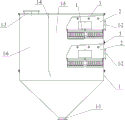
Fig. 1 is a schematic cross-sectional structure diagram of a dust remover for shunting dust removal according to an example of the present invention;
FIG. 2 is an enlarged view of a portion of FIG. 1;
FIG. 3 is a schematic plan view of 2-1 of FIG. 2;
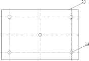
FIG. 4 is a schematic plan view of FIGS. 2-4;
FIG. 5 is another schematic plan view of FIGS. 2-4;
in the figure:
1. a box body; 1-1, a sewage outlet; 1-2, waste gas inlet; 1-3, a purified gas outlet; 1-4, a partition board; 1-5, a dust removal cavity; 1-6, a clean air cavity;
2. a dust removal device; 2-1, an air guide tube; 2-2, vent holes; 2-3, an overflow tray; 2-4, water permeable holes;
3. an atomized water spray head.
Detailed Description
To clearly illustrate the design concept of the present invention, the following description is made with reference to the examples.
In order to make the technical solutions of the present invention better understood by those skilled in the art, the technical solutions in the embodiments of the present invention are clearly and completely described below with reference to the drawings in the examples of the present invention, and it is obvious that the described examples are only a part of examples of the present invention, and not all examples. Based on the middle examples of the present invention, all other embodiments obtained by a person of ordinary skill in the art without creative efforts shall fall within the protection scope of the present invention.
In the description of the present embodiment, the terms "upper", "lower", "left", "right", and the like indicate orientations or positional relationships based on those shown in the drawings, and are only for convenience of description and simplification of description, but do not indicate or imply that the device or element referred to must have a specific orientation, be constructed and operated in a specific orientation, and thus, should not be construed as limiting the present invention.
As shown in FIGS. 1-5, a first embodiment of the dust collector for shunting dust collection of the present invention is provided, as shown in FIG. 1, which is a schematic sectional structure of the dust collector, the dust collector comprises a box body 1, a sewage outlet 1-1 is provided at the bottom of the box body 1 for discharging the water containing sludge after dust collection out of the box body 1, in this example, the bottom of the box body 1 provided with the sewage outlet 1-1 is set to be a tapered structure, so as to facilitate the collection of the sewage containing sludge after dust collection for discharging the box body from the sewage outlet 1-1. The upper part of the box body 1 is provided with a dust removal device 2; an air inlet cavity of the dust removal device 2 is communicated with a waste gas inlet 1-2 arranged on the box body 1, as shown in figure 2, the dust removal device 2 comprises an overflow disc 2-3 for containing water and a plurality of air guide pipes 2-1 for shunting the waste gas, one end of each air guide pipe 2-1 is communicated with the air inlet cavity, the other end of each air guide pipe 2-1 is immersed in the water of the overflow disc 2-3, and the bottom of the overflow disc 2-3 is provided with a plurality of water permeable holes 2-4 for discharging sludge precipitated at the bottom of the disc; as shown in fig. 1, two sets of dust collectors 2 are divided into an upper layer and a lower layer and arranged in the box 1, and in other embodiments of the present invention, other numbers of dust collectors may be arranged in layers or in a single layer. The upper part of the dust removing device 2 is provided with a plurality of atomized water spray heads 3, as shown in figure 1, in the present example, the upper part of each dust removing device 2 is provided with 3 atomized water spray heads 3, in the present example, the atomized water spray heads 3 can continuously supply water to the overflow disc 2-3, so that the other end of the air duct 2-1 is always immersed in the water; the top of the box body 1 is provided with a purified gas outlet 1-3.
As shown in figure 2, a plurality of vent holes 2-2 are uniformly formed in the side wall of the air guide tube 2-1 immersed in water, and through the arrangement of the vent holes 2-2, introduced waste gas can be in contact with water more fully, so that the dust removal effect is improved. The end face of the air duct 2-1 immersed in water is arranged to be zigzag, which is equivalent to increase the area of the end face of the air duct 2-1 for discharging waste gas, increase the contact area of the waste gas and the water, and further improve the dust removal effect.
Referring to FIG. 3, which shows a plan view of the air tubes 2-1 in this example, the air tubes 2-1 are arranged in a regular rectangular array with a width and a length of 8X 5, and a total of 40 air tubes 2-1 are arranged above an overflow tray 2-3. As shown in FIG. 4, the water permeable holes 2-4 in this example are a plane distribution diagram, wherein 5 water permeable holes 2-4 are formed at the bottom of each overflow tray 2-3, the distribution of the 5 water permeable holes is 1 at the center, 1 is at each of four corners, and the diameter of each water permeable hole is 8-20 mm, preferably 12 mm.
As shown in FIG. 5, in another plane distribution diagram of the water permeable holes 2-4 in this example, 9 water permeable holes 2-4 are formed at the bottom of each overflow tray 2-3, and the 9 water permeable holes are arranged horizontally and vertically at 3X 3.
As shown in figure 1, a partition plate 1-4 is arranged in a box body 1, the partition plate 1-4 longitudinally divides the box body 1 into a dust removing cavity 1-5 and a gas purifying cavity 1-6, a dust removing device 2 is positioned in the dust removing cavity 1-5, a gas purifying outlet 1-3 is communicated with the gas purifying cavity 1-6, and the dust removing cavity 1-5 at the bottom of the box body 1 is communicated with the gas purifying cavity 1-6. The dedusted clean waste gas enters the clean gas cavity 1-6 through the partition plate 1-4 and is discharged through the clean gas outlet 1-3 arranged at the top of the gas inlet cavity 1-6.
This example reposition of redundant personnel dust removal's dust remover through set up the hole of permeating water 2-4 in the bottom of overflow dish 2-3 with the mud of deposit in overflow dish 2-3 discharge, simultaneously through setting up moisturizing in dust collector 2 upper portion atomizing water shower nozzle 3 to overflow dish 2-3, make the other end of air duct 2-1 submergence in the aquatic all the time, guarantee going on continuously of waste gas dust removal work, this process can alleviate the influence of mud in the aquatic to removing dust to a great extent, make full use of the water in the overflow dish 2-3 volume space and waste gas contact, in order to reach better dust removal effect. And, every dust collector 2's atomizing water shower nozzle 3 independent setting, the risk that the atomizing water shower nozzle 3 of lower floor blockked up among the prior art can not exist.
It is noted that some of the structures may be selected differently than the specific examples given above. For example, the arrangement of the number of the air ducts above each overflow disc and the arrangement of the number of the water permeable holes below the overflow disc need to be set according to the size of the overflow disc and the actual need of dust removal; the water spraying amount of the atomizing water spray head is matched with the number and the size of the water permeable holes of the overflow disc, so that sufficient water in the overflow disc is ensured to immerse the other end of the air duct all the time; and the like, which can be made by those skilled in the art based on their basic skills based on an understanding of the inventive concept, and are not to be taken as an example herein.
Finally, it is to be understood that the above embodiments are merely exemplary embodiments that have been employed to illustrate the principles of the present invention, and that the present invention is not limited thereto. It will be apparent to those skilled in the art that various changes and modifications can be made without departing from the spirit and scope of the invention, and these changes and modifications are to be considered as the protection scope of the invention.
Claims (5)
1. The dust remover for shunting dust removal is characterized by comprising a box body, wherein a sewage outlet is formed in the bottom of the box body, and a dust removal device is mounted at the upper part of the box body; an air inlet cavity of the dust removal device is communicated with a waste gas inlet arranged on the box body, the dust removal device comprises an overflow disc for containing water and a plurality of air guide pipes, one end of each air guide pipe is communicated with the air inlet cavity, the other end of each air guide pipe is immersed in the water of the overflow disc, and the bottom of the overflow disc is provided with a plurality of water permeable holes; the upper part of the dust removal device is provided with a plurality of atomized water nozzles; the top of the box body is provided with a purified gas outlet.
2. The deduster according to claim 1, wherein a plurality of vent holes are uniformly formed in the side wall of the lower end of the gas guide tube immersed in water, and the end surface of the gas guide tube immersed in water is arranged in a zigzag shape.
3. A precipitator in accordance with claim 1, wherein the diameter of the water permeable holes is 8-20 mm.
4. The precipitator of claim 1, wherein a plurality of sets of the dust removing devices are installed in the tank in a layered arrangement or a single-layer staggered arrangement.
5. A precipitator in accordance with any one of claims 1-4, wherein a partition is provided in the housing, the partition longitudinally dividing the housing into a dust removal chamber and a clean air chamber, the dust removal device being located in the dust removal chamber, the clean air outlet being in communication with the clean air chamber, the dust removal chamber being in communication with the clean air chamber at the bottom of the housing.
Priority Applications (1)
| Application Number | Priority Date | Filing Date | Title |
|---|---|---|---|
| CN202020176147.7U CN212166883U (en) | 2020-02-18 | 2020-02-18 | Dust remover with shunting dust removal function |
Applications Claiming Priority (1)
| Application Number | Priority Date | Filing Date | Title |
|---|---|---|---|
| CN202020176147.7U CN212166883U (en) | 2020-02-18 | 2020-02-18 | Dust remover with shunting dust removal function |
Publications (1)
| Publication Number | Publication Date |
|---|---|
| CN212166883U true CN212166883U (en) | 2020-12-18 |
Family
ID=73774192
Family Applications (1)
| Application Number | Title | Priority Date | Filing Date |
|---|---|---|---|
| CN202020176147.7U Active CN212166883U (en) | 2020-02-18 | 2020-02-18 | Dust remover with shunting dust removal function |
Country Status (1)
| Country | Link |
|---|---|
| CN (1) | CN212166883U (en) |
-
2020
- 2020-02-18 CN CN202020176147.7U patent/CN212166883U/en active Active
Similar Documents
| Publication | Publication Date | Title |
|---|---|---|
| CN210786823U (en) | Based on desulphurization unit for flue gas purification of thermal power plant | |
| KR101197711B1 (en) | Water jet type dust collector | |
| CN212417350U (en) | High-efficient wet dust collector of porous medium | |
| CN1915473A (en) | Multifunctional rinsing type air purifier | |
| CN212166883U (en) | Dust remover with shunting dust removal function | |
| CN207413063U (en) | A kind of combined type flue gas removing device | |
| CN209952474U (en) | Liquid washing air purifier | |
| CN212548841U (en) | Oil fume purifier | |
| CN212632244U (en) | Multi-effect cyclone spray tower | |
| CN201175637Y (en) | Water curtain spray eliminator | |
| CN213314210U (en) | Be suitable for full-automatic exhaust gas collection device who sprays paint | |
| CN110975470B (en) | Wet dust collector for high-temperature flue gas purification | |
| CN112755715A (en) | Flue gas filtering device | |
| CN213314151U (en) | PM2.5 air purifier | |
| CN216878500U (en) | High-efficient multiple-layer filtering wet dust collector | |
| CN213253605U (en) | Mixing chamber wet dust collector | |
| CN214914591U (en) | Pump-free water curtain dust remover | |
| CN215692688U (en) | Dust remover | |
| CN215311214U (en) | Tube bank defroster | |
| CN214345539U (en) | Desulfurization dust collecting equipment and flue gas treatment equipment | |
| CN212974583U (en) | High-efficient wet dust collector of tiny particle thing that contains porous medium | |
| CN216935286U (en) | Dust and waste gas tower | |
| CN214914540U (en) | Treatment device for diffused gas in ferrosilicon smelting process | |
| CN218608642U (en) | Spray dust remover | |
| CN219879431U (en) | Water tank spraying device of dust remover of sanding machine |
Legal Events
| Date | Code | Title | Description |
|---|---|---|---|
| GR01 | Patent grant | ||
| GR01 | Patent grant |