CN212144565U - Full-automatic three-dimensional drilling device - Google Patents
Full-automatic three-dimensional drilling device Download PDFInfo
- Publication number
- CN212144565U CN212144565U CN202020811405.4U CN202020811405U CN212144565U CN 212144565 U CN212144565 U CN 212144565U CN 202020811405 U CN202020811405 U CN 202020811405U CN 212144565 U CN212144565 U CN 212144565U
- Authority
- CN
- China
- Prior art keywords
- vertical
- motor
- drilling
- bracket
- device main
- Prior art date
- Legal status (The legal status is an assumption and is not a legal conclusion. Google has not performed a legal analysis and makes no representation as to the accuracy of the status listed.)
- Expired - Fee Related
Links
Images



Landscapes
- Drilling And Boring (AREA)
Abstract
本实用新型公开了一种全自动三维钻孔装置,包括底板、装置主体、工作台和夹具,所述装置主体的两侧均固定安装有纵向移动组件,两个所述纵向移动组件的一侧分别固定安装有可移动的第一支架和第二支架,所述第一支架和第二支架的一侧分别固定安装有竖向移动组件和横向移动组件,所述竖向移动组件和横向移动组件的一侧分别固定安装有可移动的横向钻机和竖向钻机。本实用新型通过第一电机控制工作台进行旋转,从而可调整工件的钻孔角度,通过竖向移动组件调整横向钻机的钻孔高度,通过横向移动组件调整竖向钻机的横向钻孔位置,从而便于从多个不同方向对工件进行钻孔操作,提高工作效率,降低工人劳动的工作量。

The utility model discloses a fully automatic three-dimensional drilling device, comprising a bottom plate, a device main body, a worktable and a clamp. Longitudinal moving assemblies are fixedly installed on both sides of the device main body, and one side of the two longitudinal moving assemblies A movable first bracket and a second bracket are fixedly installed respectively, and a vertical movement component and a lateral movement component are respectively fixedly installed on one side of the first bracket and the second bracket, and the vertical movement component and the lateral movement component are respectively fixed and installed A movable horizontal drilling rig and a vertical drilling rig are fixedly installed on one side of the rig. The utility model controls the rotation of the worktable by the first motor, so that the drilling angle of the workpiece can be adjusted, the drilling height of the horizontal drilling machine is adjusted by the vertical moving component, and the horizontal drilling position of the vertical drilling machine is adjusted by the lateral moving component, thereby It is convenient to drill the workpiece from multiple different directions, improve work efficiency and reduce the workload of workers.
Description
技术领域technical field
本实用新型涉及机加工设备技术领域,具体为全自动三维钻孔装置。The utility model relates to the technical field of machining equipment, in particular to an automatic three-dimensional drilling device.
背景技术Background technique
在对某些工件进行钻孔加工时,如果工件的体积较大,或工件的整体结构较为复杂,或需要在多个不同方向上进行钻孔操作时,则无法使用传统的自动钻孔设备进行操作,只能采用人工操作的方式进行,而人工操作不仅工作效率低下,而且需要耗费大量的劳动量,因此现在需要一种能够解决上述问题的全自动三维钻孔装置。When drilling some workpieces, if the volume of the workpiece is large, or the overall structure of the workpiece is complex, or when drilling operations need to be performed in multiple different directions, it is impossible to use traditional automatic drilling equipment. The operation can only be carried out by manual operation, and the manual operation is not only inefficient, but also requires a lot of labor. Therefore, a fully automatic three-dimensional drilling device that can solve the above problems is required.
实用新型内容Utility model content
本实用新型的目的在于提供全自动三维钻孔装置以解决上述背景技术中提出的问题。The purpose of the present invention is to provide a fully automatic three-dimensional drilling device to solve the above-mentioned problems in the background art.
为实现上述目的,本实用新型提供如下技术方案:全自动三维钻孔装置,包括底板,所述底板的上表面固定连接有装置主体,所述装置主体的上表面设置有工作台,所述工作台的上表面固定安装有夹具,所述装置主体的两侧均固定安装有纵向移动组件,两个所述纵向移动组件的一侧分别固定安装有可移动的第一支架和第二支架,所述第一支架和第二支架的一侧分别固定安装有竖向移动组件和横向移动组件,所述竖向移动组件和横向移动组件的一侧分别固定安装有可移动的横向钻机和竖向钻机。In order to achieve the above purpose, the present invention provides the following technical solutions: a fully automatic three-dimensional drilling device, comprising a bottom plate, the upper surface of the bottom plate is fixedly connected with a device main body, the upper surface of the device main body is provided with a workbench, the A clamp is fixedly installed on the upper surface of the table, longitudinal moving components are fixedly installed on both sides of the device main body, and a movable first bracket and a second bracket are fixedly installed on one side of the two longitudinally moving components, respectively. One side of the first bracket and the second bracket are respectively fixed with a vertical moving assembly and a lateral moving assembly, and one side of the vertical moving assembly and the lateral moving assembly are respectively fixed and installed with a movable lateral drilling rig and a vertical drilling rig .
优选的,所述夹具包括固定板、限位螺母、螺杆、旋钮和夹块,所述固定板与工作台的上表面固定连接,所述固定板的一侧固定安装有限位螺母,所述限位螺母的内部螺纹连接有螺杆,所述螺杆的一端固定连接有旋钮,所述螺杆的另一端活动连接有夹块。Preferably, the clamp includes a fixing plate, a limit nut, a screw rod, a knob and a clamping block, the fixing plate is fixedly connected to the upper surface of the worktable, a limit nut is fixedly installed on one side of the fixing plate, and the limit A screw is connected with the internal thread of the position nut, one end of the screw is fixedly connected with a knob, and the other end of the screw is movably connected with a clamping block.
优选的,所述工作台的内部固定安装有第一电机,所述第一电机的输出端与工作台下表面的中部固定连接。Preferably, a first motor is fixedly installed inside the worktable, and the output end of the first motor is fixedly connected to the middle of the lower surface of the worktable.
优选的,所述装置主体上表面的中部固定安装有轴座。Preferably, an axle seat is fixedly installed in the middle of the upper surface of the device main body.
优选的,所述纵向移动组件、竖向移动组件和横向移动组件的结构均相同。Preferably, the structures of the longitudinal moving assembly, the vertical moving assembly and the lateral moving assembly are all the same.
优选的,所述横向移动组件包括壳体、第二电机、丝杆和移动块,所述壳体的一端固定安装有第二电机,所述第二电机的输出端固定连接有丝杆,所述丝杆的表面螺纹连接有移动块。Preferably, the lateral movement assembly includes a casing, a second motor, a lead screw and a moving block, one end of the casing is fixedly mounted with a second motor, and an output end of the second motor is fixedly connected with a lead screw, so The surface of the screw rod is threadedly connected with a moving block.
优选的,所述第一支架、第二支架、横向钻机和竖向钻机均与移动块固定安装。Preferably, the first support, the second support, the horizontal drilling machine and the vertical drilling machine are all fixedly installed with the moving block.
与现有技术相比,本实用新型的有益效果是:Compared with the prior art, the beneficial effects of the present utility model are:
1、本实用新型通过两个纵向移动组件的设置,能够分别带动第一支架和第二支架纵向移动,从而可调整横向钻机和竖向钻机的纵向钻孔位置,通过竖向移动组件的设置,能够带动横向钻机竖向移动,从而可调整横向钻机的钻孔高度,通过横向移动组件的设置,能够带动竖向钻机横向移动,从而可调整竖向钻机的横向钻孔位置,从而便于从多个不同方向对工件进行钻孔操作,提高工作效率,降低工人劳动的工作量。1. The utility model can drive the first bracket and the second bracket to move longitudinally through the arrangement of the two longitudinal moving components, so that the longitudinal drilling positions of the horizontal drilling rig and the vertical drilling rig can be adjusted. It can drive the horizontal drilling rig to move vertically, so that the drilling height of the horizontal drilling rig can be adjusted. Drilling the workpiece in different directions improves work efficiency and reduces the workload of workers.
2、本实用新型通过第一电机的设置,能够控制工作台进行旋转,从而可调整工件的钻孔角度。2. The utility model can control the rotation of the worktable through the arrangement of the first motor, so that the drilling angle of the workpiece can be adjusted.
附图说明Description of drawings
图1为本实用新型主视结构示意图;Fig. 1 is the front view structure schematic diagram of the utility model;
图2为本实用新型主视剖面结构示意图;Fig. 2 is the front view sectional structure schematic diagram of the utility model;
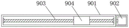
图3为本实用新型横向移动组件的内部结构示意图;3 is a schematic diagram of the internal structure of the lateral movement assembly of the present invention;
图4为本实用新型夹具的结构示意图。FIG. 4 is a schematic structural diagram of the fixture of the present invention.
图中:1、底板;2、装置主体;3、工作台;4、夹具;401、固定板;402、限位螺母;403、螺杆;404、旋钮;405、夹块;5、纵向移动组件;6、第一支架;7、第二支架;8、竖向移动组件;9、横向移动组件;901、壳体;902、第二电机;903、丝杆;904、移动块;10、横向钻机;11、竖向钻机;12、第一电机;13、轴座。In the figure: 1. Bottom plate; 2. Device body; 3. Workbench; 4. Clamp; 401, Fixing plate; 402, Limit nut; 403, Screw; 404, Knob; 405, Clamping block; ; 6, the first bracket; 7, the second bracket; 8, the vertical movement assembly; 9, the lateral movement assembly; 901, the shell; 902, the second motor; 903, the screw; 904, the moving block; Drilling rig; 11. Vertical drilling rig; 12. The first motor; 13. Shaft seat.
具体实施方式Detailed ways
下面将结合本实用新型实施例中的附图,对本实用新型实施例中的技术方案进行清楚、完整地描述,显然,所描述的实施例仅仅是本实用新型一部分实施例,而不是全部的实施例。基于本实用新型中的实施例,本领域普通技术人员在没有做出创造性劳动前提下所获得的所有其他实施例,都属于本实用新型保护的范围。The technical solutions in the embodiments of the present utility model will be clearly and completely described below with reference to the accompanying drawings in the embodiments of the present utility model. Obviously, the described embodiments are only a part of the embodiments of the present utility model, rather than all the implementations. example. Based on the embodiments of the present invention, all other embodiments obtained by those of ordinary skill in the art without creative work fall within the protection scope of the present invention.
在本实用新型的描述中,需要说明的是,术语“上”、“下”、“内”、“外”“前端”、“后端”、“两端”、“一端”、“另一端”等指示的方位或位置关系为基于附图所示的方位或位置关系,仅是为了便于描述本实用新型和简化描述,而不是指示或暗示所指的装置或元件必须具有特定的方位、以特定的方位构造和操作,因此不能理解为对本实用新型的限制。此外,术语“第一”、“第二”仅用于描述目的,而不能理解为指示或暗示相对重要性。In the description of the present invention, it should be noted that the terms "upper", "lower", "inner", "outer", "front end", "rear end", "two ends", "one end", "the other end" The orientation or positional relationship indicated by "" etc. is based on the orientation or positional relationship shown in the accompanying drawings, and is only for the convenience of describing the present invention and simplifying the description, rather than indicating or implying that the indicated device or element must have a specific orientation, so as to The specific orientation configuration and operation is therefore not to be construed as a limitation of the present invention. Furthermore, the terms "first" and "second" are used for descriptive purposes only and should not be construed to indicate or imply relative importance.
在本实用新型的描述中,需要说明的是,除非另有明确的规定和限定,术语“安装”、“设置有”、“连接”等,应做广义理解,例如“连接”,可以是固定连接,也可以是可拆卸连接,或一体地连接;可以是机械连接,也可以是电连接;可以是直接相连,也可以通过中间媒介间接相连,可以是两个元件内部的连通。对于本领域的普通技术人员而言,可以具体情况理解上述术语在本实用新型中的具体含义。In the description of the present utility model, it should be noted that, unless otherwise expressly specified and limited, the terms "installed", "provided with", "connected", etc., should be understood in a broad sense, for example, "connected" may be a fixed The connection can also be a detachable connection, or an integral connection; it can be a mechanical connection or an electrical connection; it can be a direct connection, or an indirect connection through an intermediate medium, and it can be internal communication between two components. For those of ordinary skill in the art, the specific meanings of the above terms in the present invention can be understood in specific situations.
请参阅图1-4,本实用新型提供的一种实施例:全自动三维钻孔装置,包括底板1,底板1的上表面固定连接有装置主体2,装置主体2的上表面设置有工作台3,工作台3的上表面固定安装有夹具4,装置主体2的两侧均固定安装有纵向移动组件5,两个纵向移动组件5的一侧分别固定安装有可移动的第一支架6和第二支架7,第一支架6和第二支架7的一侧分别固定安装有竖向移动组件8和横向移动组件9,竖向移动组件8和横向移动组件9的一侧分别固定安装有可移动的横向钻机10和竖向钻机11,通过两个纵向移动组件5 的设置,能够分别带动第一支架6和第二支架7纵向移动,从而可调整横向钻机10和竖向钻机11的纵向钻孔位置,通过竖向移动组件8的设置,能够带动横向钻机10竖向移动,从而可调整横向钻机10的钻孔高度,通过横向移动组件9的设置,能够带动竖向钻机11横向移动,从而可调整竖向钻机11 的横向钻孔位置,从而便于从多个不同方向对工件进行钻孔操作,提高工作效率,降低工人劳动的工作量。Please refer to Figures 1-4, an embodiment provided by the present invention: a fully automatic three-dimensional drilling device, comprising a
进一步,夹具4包括固定板401、限位螺母402、螺杆403、旋钮404和夹块405,固定板401与工作台3的上表面固定连接,固定板401的一侧固定安装有限位螺母402,限位螺母402的内部螺纹连接有螺杆403,螺杆403的一端固定连接有旋钮404,螺杆403的另一端活动连接有夹块405,通过夹具 4的设置,能够对待加工工件进行夹持。Further, the
进一步,工作台3的内部固定安装有第一电机12,第一电机12的输出端与工作台3下表面的中部固定连接,通过第一电机12的设置,能够控制工作台3进行旋转,从而可调整工件的钻孔角度。Further, a first motor 12 is fixedly installed inside the
进一步,装置主体2上表面的中部固定安装有轴座13,通过轴座13的设置,能够提高工作台3的稳定性。Further, a
进一步,纵向移动组件5、竖向移动组件8和横向移动组件9的结构均相同,通过纵向移动组件5、竖向移动组件8和横向移动组件9的设置,能够分别为纵向移动、竖向移动和水平移动提供动力。Further, the structures of the
进一步,横向移动组件9包括壳体901、第二电机902、丝杆903和移动块904,壳体901的一端固定安装有第二电机902,第二电机902的输出端固定连接有丝杆903,丝杆903的表面螺纹连接有移动块904,通过壳体901、第二电机902、丝杆903和移动块904的配合,使用第二电机902驱动丝杆 903转动,能够使移动块904沿丝杆903进行移动。Further, the
进一步,第一支架6、第二支架7、横向钻机10和竖向钻机11均与移动块904固定安装,通过移动块904的移动分别带动第一支架6、第二支架7、横向钻机10和竖向钻机11进行运动。Further, the
工作原理:在使用时,通过夹具4的设置,能够对待加工工件进行夹持,通过第一电机12控制工作台3进行旋转,从而可调整工件的钻孔角度,通过两个纵向移动组件5分别带动第一支架6和第二支架7纵向移动,从而可调整横向钻机10和竖向钻机11的纵向钻孔位置,通过竖向移动组件8调整横向钻机10的钻孔高度,通过横向移动组件9调整竖向钻机11的横向钻孔位置,从而便于从多个不同方向对工件进行钻孔操作,提高工作效率,降低工人劳动的工作量。Working principle: During use, the workpiece to be processed can be clamped by the setting of the
对于本领域技术人员而言,显然本实用新型不限于上述示范性实施例的细节,而且在不背离本实用新型的精神或基本特征的情况下,能够以其他的具体形式实现本实用新型。因此,无论从哪一点来看,均应将实施例看作是示范性的,而且是非限制性的,本实用新型的范围由所附权利要求而不是上述说明限定,因此旨在将落在权利要求的等同要件的含义和范围内的所有变化囊括在本实用新型内。不应将权利要求中的任何附图标记视为限制所涉及的权利要求。It will be apparent to those skilled in the art that the present invention is not limited to the details of the above-described exemplary embodiments, and that the present invention may be implemented in other specific forms without departing from the spirit or essential characteristics of the present invention. Therefore, the embodiments are to be considered in all respects as exemplary and not restrictive, and the scope of the present invention is defined by the appended claims rather than the foregoing description, and it is therefore intended that the All changes within the meaning and range of the required equivalents are embraced within the present invention. Any reference signs in the claims shall not be construed as limiting the involved claim.
Claims (7)
Priority Applications (1)
| Application Number | Priority Date | Filing Date | Title |
|---|---|---|---|
| CN202020811405.4U CN212144565U (en) | 2020-05-15 | 2020-05-15 | Full-automatic three-dimensional drilling device |
Applications Claiming Priority (1)
| Application Number | Priority Date | Filing Date | Title |
|---|---|---|---|
| CN202020811405.4U CN212144565U (en) | 2020-05-15 | 2020-05-15 | Full-automatic three-dimensional drilling device |
Publications (1)
| Publication Number | Publication Date |
|---|---|
| CN212144565U true CN212144565U (en) | 2020-12-15 |
Family
ID=73706884
Family Applications (1)
| Application Number | Title | Priority Date | Filing Date |
|---|---|---|---|
| CN202020811405.4U Expired - Fee Related CN212144565U (en) | 2020-05-15 | 2020-05-15 | Full-automatic three-dimensional drilling device |
Country Status (1)
| Country | Link |
|---|---|
| CN (1) | CN212144565U (en) |
Cited By (3)
| Publication number | Priority date | Publication date | Assignee | Title |
|---|---|---|---|---|
| CN114226785A (en) * | 2021-11-08 | 2022-03-25 | 广州通发智能装备股份有限公司 | Numerical control machine tool with double-sided punching function |
| CN114406787A (en) * | 2022-01-24 | 2022-04-29 | 北京航天衡科技有限公司 | Micro-hole machining micro CNC equipment |
| CN116727718A (en) * | 2023-08-02 | 2023-09-12 | 鄂尔多斯市市场监督管理局(鄂尔多斯市知识产权局) | Safety protection device of electromechanical equipment |
-
2020
- 2020-05-15 CN CN202020811405.4U patent/CN212144565U/en not_active Expired - Fee Related
Cited By (3)
| Publication number | Priority date | Publication date | Assignee | Title |
|---|---|---|---|---|
| CN114226785A (en) * | 2021-11-08 | 2022-03-25 | 广州通发智能装备股份有限公司 | Numerical control machine tool with double-sided punching function |
| CN114406787A (en) * | 2022-01-24 | 2022-04-29 | 北京航天衡科技有限公司 | Micro-hole machining micro CNC equipment |
| CN116727718A (en) * | 2023-08-02 | 2023-09-12 | 鄂尔多斯市市场监督管理局(鄂尔多斯市知识产权局) | Safety protection device of electromechanical equipment |
Similar Documents
| Publication | Publication Date | Title |
|---|---|---|
| CN216227881U (en) | A single-head all-round automatic CNC nut machine | |
| CN210649241U (en) | Welding tool for machining automobile swing arm | |
| CN220407620U (en) | Welding equipment | |
| CN221716228U (en) | A center positioning fixture for machining shaft workpieces on CNC lathes | |
| CN209886838U (en) | A cross slide high-speed drilling servo multi-head tapping machine | |
| CN220260182U (en) | Radial positioner for ball screw machining | |
| CN218694007U (en) | But angle modulation formula bench drill | |
| CN218744946U (en) | Multi-station machining drilling machine | |
| CN217727980U (en) | Milling deep hole drilling machine | |
| CN215420985U (en) | High-precision intelligent drilling device for circuit board machining | |
| CN221019826U (en) | Four-axis processing jig for barreled handles | |
| CN213105507U (en) | Square pipe perforating device | |
| CN212240104U (en) | An easy-to-adjust jig for making multi-hole drills for metal tools | |
| CN221290043U (en) | Workpiece fixing device for welding robot | |
| CN212071146U (en) | Clamp for machining | |
| CN222079002U (en) | A grinding machine fixture | |
| CN221870334U (en) | Bench drill of adjustable height | |
| CN217193937U (en) | Side Mounted CNC Machine Fixtures | |
| CN211387215U (en) | A special cutting machine tool for machining impeller | |
| CN212144855U (en) | Workpiece jig of numerical control tapping machine with fine adjustment function | |
| CN210996572U (en) | A CNC machine tool with stable clamping | |
| CN221658592U (en) | A guide rail workbench with a reinforcing rib structure | |
| CN220279329U (en) | Forging table mounting fixture structure | |
| CN220806001U (en) | Adjustable clamp | |
| CN216990538U (en) | Adjustable time-saving welding tool for air conditioner |
Legal Events
| Date | Code | Title | Description |
|---|---|---|---|
| GR01 | Patent grant | ||
| GR01 | Patent grant | ||
| CF01 | Termination of patent right due to non-payment of annual fee |
Granted publication date: 20201215 |
|
| CF01 | Termination of patent right due to non-payment of annual fee |