CN212135242U - A water pressure regulator for an intelligent mobile car washing machine - Google Patents
A water pressure regulator for an intelligent mobile car washing machine Download PDFInfo
- Publication number
- CN212135242U CN212135242U CN202021060050.6U CN202021060050U CN212135242U CN 212135242 U CN212135242 U CN 212135242U CN 202021060050 U CN202021060050 U CN 202021060050U CN 212135242 U CN212135242 U CN 212135242U
- Authority
- CN
- China
- Prior art keywords
- baffle
- connecting pipe
- water pressure
- pressure regulator
- sleeve
- Prior art date
- Legal status (The legal status is an assumption and is not a legal conclusion. Google has not performed a legal analysis and makes no representation as to the accuracy of the status listed.)
- Expired - Fee Related
Links
Images


Landscapes
- Nozzles (AREA)
Abstract
本实用新型公开了一种智能移动洗车机的水压调节器,包括第一挡板、本体、底座、压力表和第二挡板,所述底座顶端的中央位置处设置有安装轴,所述第二连接管的上表面设置有本体,且所述本体内部的中央位置处竖向设置有滑杆,且所述滑杆中间位置处套设有活动套,所述活动套底端设置有辅助板,所述滑杆顶端的本体内部设置有固定套,且所述固定套底端的两侧均铰接有第二挡板,所述活动套顶端的两侧均铰接有第一挡板,且所述第一挡板顶端均与第二挡板底端铰接,所述固定套与所述活动套之间的滑杆外侧缠绕有弹簧。本实用新型通过弹簧的设置,配合第一挡板与第二挡板的作用,便于实现对水压的自动控制,实用性较好。
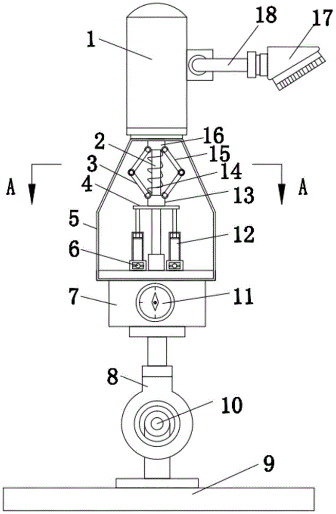
The utility model discloses a water pressure regulator for an intelligent mobile car washing machine, which comprises a first baffle, a body, a base, a pressure gauge and a second baffle. An installation shaft is arranged at the central position of the top of the base. The upper surface of the second connecting pipe is provided with a main body, and a sliding rod is arranged vertically at the central position inside the main body, and a movable sleeve is sleeved at the middle position of the sliding rod, and the bottom end of the movable sleeve is provided with an auxiliary A fixed sleeve is arranged inside the body at the top end of the sliding rod, and both sides of the bottom end of the fixed sleeve are hinged with a second baffle plate, and both sides of the top end of the movable sleeve are hinged with a first baffle plate. The top end of the first baffle is hinged with the bottom end of the second baffle, and a spring is wound on the outer side of the sliding rod between the fixed sleeve and the movable sleeve. Through the arrangement of the spring, the utility model cooperates with the functions of the first baffle plate and the second baffle plate, which facilitates the automatic control of the water pressure and has good practicability.
Description
技术领域technical field
本实用新型涉及水压调节技术领域,具体为一种智能移动洗车机的水压调节器。The utility model relates to the technical field of water pressure regulation, in particular to a water pressure regulator of an intelligent mobile car washing machine.
背景技术Background technique
移动洗车,顾名思义就是有别于传统的店面洗车,实现了简单汽车美容清洗可移动化的上门服务。移动洗车,洗车高压蒸汽设备,专门从事电热蒸汽清洗机和移动蒸汽清洗机的制造、销售、服务。适合上门洗车,不受电源局限、排污困扰、场所限制,现有的水压调节器一般采用感应设备实现自动调节过程,一方面成本过大,另一方面使得水压调节器体积过大,不便于工作,携带。Mobile car wash, as the name suggests, is different from the traditional storefront car wash, and realizes the mobile door-to-door service of simple car beauty cleaning. Mobile car washing, car washing high pressure steam equipment, specializing in the manufacture, sales and service of electric steam cleaning machines and mobile steam cleaning machines. It is suitable for door-to-door car washing, and is not limited by power supply, sewage, and place. The existing water pressure regulator generally uses induction equipment to realize the automatic adjustment process. On the one hand, the cost is too large, and on the other hand, the water pressure regulator is too large and not suitable Easy to work and carry.
实用新型内容Utility model content
本实用新型的目的在于提供一种智能移动洗车机的水压调节器,通过弹簧的设置,配合第一挡板与第二挡板的作用,便于实现对水压的自动控制,实用性较好,解决了背景技术中提出的问题。The purpose of the utility model is to provide a water pressure regulator for an intelligent mobile car washing machine. Through the setting of the spring and the functions of the first baffle and the second baffle, it is convenient to realize the automatic control of the water pressure and has good practicability. , which solves the problems raised in the background art.
为实现上述目的,本实用新型提供如下技术方案:一种智能移动洗车机的水压调节器,包括第一挡板、本体、底座、压力表和第二挡板,所述底座顶端的中央位置处设置有安装轴,且所述安装轴上套设有轴套,所述轴套顶端设置有第二连接管,且所述第二连接管的正面设置有压力表,所述第二连接管的上表面设置有本体,且所述本体内部的中央位置处竖向设置有滑杆,且所述滑杆中间位置处套设有活动套,所述活动套底端设置有辅助板,所述滑杆顶端的本体内部设置有固定套,且所述固定套底端的两侧均铰接有第二挡板,所述活动套顶端的两侧均铰接有第一挡板,且所述第一挡板顶端均与第二挡板底端铰接,所述固定套与所述活动套之间的滑杆外侧缠绕有弹簧,所述本体顶端设置有第一连接管,且所述第一连接管一侧的中间位置处设置有安装管,且所述安装管的一端设置有喷头。In order to achieve the above purpose, the utility model provides the following technical solutions: a water pressure regulator for an intelligent mobile car washing machine, comprising a first baffle, a body, a base, a pressure gauge and a second baffle, the central position of the top of the base is There is an installation shaft at the place, and the installation shaft is sleeved with a shaft sleeve, the top of the shaft sleeve is provided with a second connection pipe, and the front of the second connection pipe is provided with a pressure gauge, A main body is arranged on the upper surface of the main body, and a sliding rod is arranged vertically at the central position inside the main body, and a movable sleeve is sleeved at the middle position of the sliding rod, and an auxiliary plate is arranged at the bottom end of the movable sleeve. A fixed sleeve is arranged inside the body of the top end of the sliding rod, and both sides of the bottom end of the fixed sleeve are hinged with a second baffle plate, and both sides of the top end of the movable sleeve are hinged with a first baffle plate, and the first baffle plate is hinged on both sides. The top end of the plate is hinged with the bottom end of the second baffle plate, the outer side of the sliding rod between the fixed sleeve and the movable sleeve is wound with a spring, the top of the main body is provided with a first connecting pipe, and the first connecting pipe is a An installation pipe is arranged at the middle position of the side, and a spray head is arranged at one end of the installation pipe.
优选的,所述本体内部的底端对称设置有气缸,且所述气缸的输出端设置有伸缩杆,所述伸缩杆顶端均与辅助板底端焊接。Preferably, a cylinder is symmetrically arranged at the bottom end inside the body, and a telescopic rod is arranged at the output end of the cylinder, and the top end of the telescopic rod is welded with the bottom end of the auxiliary plate.
优选的,所述本体与所述第二连接管之间螺纹连接,且所述本体与所述第一连接管之间螺纹连接。Preferably, the main body and the second connecting pipe are connected by screws, and the main body and the first connecting pipe are connected by screws.
优选的,所述安装轴与所述轴套之间转动连接,且所述轴套顶端通过导管与第二连接管内部连通。Preferably, the installation shaft and the shaft sleeve are rotatably connected, and the top end of the shaft sleeve is communicated with the inside of the second connecting pipe through a conduit.
优选的,所述本体的正面设置有显示窗,且所述显示窗一侧的下端设置有调节按钮。Preferably, a display window is arranged on the front of the body, and an adjustment button is arranged at the lower end of one side of the display window.
优选的,所述第一挡板与第二挡板呈“半圆”形,所述本体呈“轮台”形。Preferably, the first baffle and the second baffle are in a "semi-circle" shape, and the body is in a "wheel platform" shape.
与现有技术相比,本实用新型的有益效果如下:Compared with the prior art, the beneficial effects of the present utility model are as follows:
1、本实用新型通过设置的第一挡板和第二挡板,当自动控制时,水压过大时会迫使辅助板向上移动,从而带动活动套在滑杆外侧向上滑动并挤压弹簧,同时实现第一挡板与第二挡板相互靠拢,使得第一挡板与第二挡板的垂直投影面积发生改变,利用投影面积的遮挡作用,从而实现出水口大小的调节,由于第一挡板与第二挡板的结构设计,配合本体的设置,当水压越大时,辅助板上升程度越大,使得出水口越小,避免水量过大造成浪费;当水压较小时,辅助板受到阻力越小,第二挡板与第一挡板发生分离,此时出水口较大,便于快速出水,通过弹簧的设置,便于实现对水压的自动控制,实用性较好。1. The first baffle plate and the second baffle plate of the present invention will force the auxiliary plate to move upwards when the water pressure is too large during automatic control, thereby driving the movable sleeve to slide upwards on the outside of the sliding rod and squeezing the spring, At the same time, the first baffle and the second baffle are moved closer to each other, so that the vertical projection area of the first baffle and the second baffle changes, and the shading effect of the projected area is used to adjust the size of the water outlet. The structural design of the plate and the second baffle plate is matched with the setting of the main body. When the water pressure is higher, the auxiliary plate will rise more, making the water outlet smaller, and avoiding waste caused by excessive water volume; when the water pressure is small, the auxiliary plate will rise The smaller the resistance is, the second baffle is separated from the first baffle, and the water outlet is larger at this time, which is convenient for rapid water discharge. The setting of the spring is convenient to realize the automatic control of the water pressure, and the practicability is good.
2、本实用新型通过设置的压力表,根据水的压力大小及工作需要,手动转动调节按钮,调节气缸的压力大小使得伸缩杆伸缩长度发生变化,伸缩杆进一步带动辅助板高度发生变化,从而实现对出水口进行调节,并通过设置的显示窗可观察辅助板的上升高度,从而便于实现控制喷洒高度及范围,功能性强。2. According to the pressure gauge of the water and the work needs, the utility model manually rotates the adjustment button to adjust the pressure of the cylinder so that the telescopic length of the telescopic rod changes, and the telescopic rod further drives the auxiliary plate to change the height, so as to realize The water outlet can be adjusted, and the rising height of the auxiliary board can be observed through the set display window, so as to facilitate the control of the spraying height and range, and has strong functionality.
附图说明Description of drawings
图1为本实用新型的正视剖面结构示意图;Fig. 1 is the front view sectional structure schematic diagram of the present utility model;
图2为本实用新型的外观结构示意图;Fig. 2 is the appearance structure schematic diagram of the utility model;
图3为本实用新型的第一挡板与第二挡板侧视剖面结构示意图;3 is a schematic side sectional structural diagram of the first baffle and the second baffle of the present invention;
图4为本实用新型的A-A剖面结构示意图。FIG. 4 is a schematic view of the A-A cross-sectional structure of the present invention.
图中:1、第一连接管;2、滑杆;3、第一挡板;4、辅助板;5、本体; 6、气缸;7、第二连接管;8、轴套;9、底座;10、安装轴;11、压力表; 12、伸缩杆;13、活动套;14、弹簧;15、第二挡板;16、固定套;17、喷头;18、安装管;19、显示窗;20、调节按钮。In the figure: 1. The first connecting pipe; 2. The sliding rod; 3. The first baffle plate; 4. The auxiliary plate; 5. The main body; 6. The cylinder; 7. The second connecting pipe; ;10, installation shaft; 11, pressure gauge; 12, telescopic rod; 13, movable sleeve; 14, spring; 15, second baffle; 16, fixed sleeve; 17, nozzle; 18, installation pipe; 19, display window ; 20. Adjust button.
具体实施方式Detailed ways
下面将结合本实用新型实施例中的附图,对本实用新型实施例中的技术方案进行清楚、完整地描述,显然,所描述的实施例仅仅是本实用新型一部分实施例,而不是全部的实施例。基于本实用新型中的实施例,本领域普通技术人员在没有做出创造性劳动前提下所获得的所有其他实施例,都属于本实用新型保护的范围。The technical solutions in the embodiments of the present utility model will be clearly and completely described below with reference to the accompanying drawings in the embodiments of the present utility model. Obviously, the described embodiments are only a part of the embodiments of the present utility model, rather than all the implementations. example. Based on the embodiments of the present invention, all other embodiments obtained by those of ordinary skill in the art without creative work fall within the protection scope of the present invention.
请参阅图1至图4,本实用新型提供一种技术方案:一种智能移动洗车机的水压调节器,包括第一挡板3、本体5、底座9、压力表11和第二挡板15,底座9顶端的中央位置处设置有安装轴10;Please refer to FIGS. 1 to 4 , the present invention provides a technical solution: a water pressure regulator for an intelligent mobile car washing machine, comprising a
安装轴10与轴套8之间转动连接,且轴套8顶端通过导管与第二连接管 7内部连通;Between the
通过轴套8与安装轴10的转动连接,便于调节该水压调节器的角度,同时,不使用时,可实现平放,减少占地面积,使用方便;Through the rotational connection between the
且安装轴10上套设有轴套8,轴套8顶端设置有第二连接管7,且第二连接管7的正面设置有压力表11,第二连接管7的上表面设置有本体5;And the
本体5内部的底端对称设置有气缸6,且气缸6的输出端设置有伸缩杆12,伸缩杆12顶端均与辅助板4底端焊接;The bottom end inside the
当需要控制喷洒高度及范围时,通过设置的压力表11,根据水的压力大小及工作需要,手动转动调节按钮20,调节气缸6的压力大小使得伸缩杆12 伸缩长度发生变化,伸缩杆12进一步带动辅助板4高度发生变化,从而实现对出水口进行调节;When it is necessary to control the spraying height and range, according to the pressure of the water and the work needs, manually turn the
本体5与第二连接管7之间螺纹连接,且本体5与第一连接管1之间螺纹连接;The
通过本体5与第二连接管7、本体5与第一连接管1之间螺纹连接,可对本体5进行拆卸,方便维修;Through the screw connection between the
本体5的正面设置有显示窗19,且显示窗19一侧的下端设置有调节按钮 20;The front of the
通过设置的显示窗19可观察辅助板4的上升高度,便于精准调节;The rising height of the auxiliary board 4 can be observed through the
且本体5内部的中央位置处竖向设置有滑杆2,且滑杆2中间位置处套设有活动套13,活动套13底端设置有辅助板4,滑杆2顶端的本体5内部设置有固定套16,且固定套16底端的两侧均铰接有第二挡板15,活动套13顶端的两侧均铰接有第一挡板3;And the central position inside the
第一挡板3与第二挡板15呈“半圆”形,本体5呈“轮台”形;The
由于第一挡板3与第二挡板15的结构设计,配合本体5的设置,便于对出水口大小的进行调节;Due to the structural design of the
且第一挡板3顶端均与第二挡板15底端铰接,固定套16与活动套13之间的滑杆2外侧缠绕有弹簧14,本体5顶端设置有第一连接管1,且第一连接管1一侧的中间位置处设置有安装管18,且安装管18的一端设置有喷头 17。And the top end of the
工作原理:该智能移动洗车机的水压调节器使用时,首先将底座9与洗车机固定,通过轴套8与安装轴10的转动连接,便于调节该水压调节器的角度,同时,不使用时,可实现平放,减少占地面积,使用方便;Working principle: When the water pressure regulator of the intelligent mobile car washing machine is used, firstly fix the
当自动控制时,水压过大时会迫使辅助板4向上移动,从而带动活动套 13在滑杆2外侧向上滑动并挤压弹簧14,同时实现第一挡板3与第二挡板15 相互靠拢,使得第一挡板3与第二挡板15的垂直投影面积发生改变,利用投影面积的遮挡作用,从而实现出水口大小的调节,由于第一挡板3与第二挡板15的结构设计,配合本体5的设置,当水压越大时,辅助板4上升程度越大,使得出水口越小,避免水量过大造成浪费;当水压较小时,辅助板4受到阻力越小,第二挡板15与第一挡板3发生分离,此时出水口较大,便于快速出水;During automatic control, when the water pressure is too large, the auxiliary plate 4 will be forced to move upward, thereby driving the
当需要控制喷洒高度及范围时,通过设置的压力表11,根据水的压力大小及工作需要,手动转动调节按钮20,调节气缸6的压力大小使得伸缩杆12 伸缩长度发生变化,伸缩杆12进一步带动辅助板4高度发生变化,从而实现对出水口进行调节,并通过设置的显示窗19可观察辅助板4的上升高度,便于精准调节。When it is necessary to control the spraying height and range, according to the pressure of the water and the work needs, manually turn the
尽管已经示出和描述了本实用新型的实施例,对于本领域的普通技术人员而言,可以理解在不脱离本实用新型的原理和精神的情况下可以对这些实施例进行多种变化、修改、替换和变型,本实用新型的范围由所附权利要求及其等同物限定。Although the embodiments of the present invention have been shown and described, it will be understood by those skilled in the art that various changes and modifications can be made to these embodiments without departing from the principles and spirit of the present invention , alternatives and modifications, the scope of the present invention is defined by the appended claims and their equivalents.
Claims (6)
Priority Applications (1)
| Application Number | Priority Date | Filing Date | Title |
|---|---|---|---|
| CN202021060050.6U CN212135242U (en) | 2020-06-11 | 2020-06-11 | A water pressure regulator for an intelligent mobile car washing machine |
Applications Claiming Priority (1)
| Application Number | Priority Date | Filing Date | Title |
|---|---|---|---|
| CN202021060050.6U CN212135242U (en) | 2020-06-11 | 2020-06-11 | A water pressure regulator for an intelligent mobile car washing machine |
Publications (1)
| Publication Number | Publication Date |
|---|---|
| CN212135242U true CN212135242U (en) | 2020-12-11 |
Family
ID=73684911
Family Applications (1)
| Application Number | Title | Priority Date | Filing Date |
|---|---|---|---|
| CN202021060050.6U Expired - Fee Related CN212135242U (en) | 2020-06-11 | 2020-06-11 | A water pressure regulator for an intelligent mobile car washing machine |
Country Status (1)
| Country | Link |
|---|---|
| CN (1) | CN212135242U (en) |
Cited By (1)
| Publication number | Priority date | Publication date | Assignee | Title |
|---|---|---|---|---|
| CN119329473A (en) * | 2024-12-17 | 2025-01-21 | 大连蓝波机械制造有限公司 | A maintenance device for manufacturing locomotive and its operation method |
-
2020
- 2020-06-11 CN CN202021060050.6U patent/CN212135242U/en not_active Expired - Fee Related
Cited By (1)
| Publication number | Priority date | Publication date | Assignee | Title |
|---|---|---|---|---|
| CN119329473A (en) * | 2024-12-17 | 2025-01-21 | 大连蓝波机械制造有限公司 | A maintenance device for manufacturing locomotive and its operation method |
Similar Documents
| Publication | Publication Date | Title |
|---|---|---|
| CN211275162U (en) | A swinging demoulding spraying device for a die casting machine | |
| CN211412429U (en) | A kind of spraying device for hollow ultra-thin pipe processing | |
| CN213079402U (en) | A kind of pipeline cleaning equipment for petrochemical industry | |
| CN208494638U (en) | It is a kind of spray painting, drying integrated process units | |
| CN211103858U (en) | Multidirectional regulation formula support is used in motor maintenance | |
| CN211463671U (en) | Non-atomizing arc steel inner wall rapid oiling device | |
| CN218139409U (en) | Receipts membrane device of PVC membrane calender | |
| CN218360251U (en) | Angle-adjustable aluminum alloy spraying device | |
| CN216881218U (en) | Positioning mechanism of continuous bending machine for manufacturing feed drying tower | |
| CN217322704U (en) | Dustproof decorative cloth processing is with mechanism of flattening | |
| CN116944099A (en) | Surface cleaning device of box-type transformer cabinet | |
| CN209473985U (en) | height adjustable table | |
| CN209971267U (en) | Compression molding machine of melamine tableware | |
| CN219943376U (en) | Surface spraying device for corrugated pipe production | |
| CN209633358U (en) | A kind of molding machine for gypsum board production line | |
| CN218427342U (en) | Finishing wall surface grinding equipment | |
| CN211416388U (en) | An extrusion device for the production of thermal insulation walls | |
| CN216678805U (en) | Spraying device for automobile production | |
| CN219965887U (en) | Cleaning mechanism for central air conditioner cooling water tank | |
| CN207953499U (en) | A kind of scraper-type polishing center fixture | |
| CN218232665U (en) | Plastic flat wire drawing machine | |
| CN218346697U (en) | Spraying device for finishing work | |
| CN217963066U (en) | Real mineral varnish spraying device | |
| CN222956690U (en) | Paint spraying apparatus for loudspeaker basin frame processing | |
| CN223055932U (en) | Local paint repair device for box transformer shell |
Legal Events
| Date | Code | Title | Description |
|---|---|---|---|
| GR01 | Patent grant | ||
| GR01 | Patent grant | ||
| CF01 | Termination of patent right due to non-payment of annual fee | ||
| CF01 | Termination of patent right due to non-payment of annual fee |
Granted publication date: 20201211 |