CN212123456U - English card cutting device with adjustable cutting size - Google Patents
English card cutting device with adjustable cutting size Download PDFInfo
- Publication number
- CN212123456U CN212123456U CN202020527640.9U CN202020527640U CN212123456U CN 212123456 U CN212123456 U CN 212123456U CN 202020527640 U CN202020527640 U CN 202020527640U CN 212123456 U CN212123456 U CN 212123456U
- Authority
- CN
- China
- Prior art keywords
- gear
- cutting
- links
- english card
- cutting device
- Prior art date
- Legal status (The legal status is an assumption and is not a legal conclusion. Google has not performed a legal analysis and makes no representation as to the accuracy of the status listed.)
- Expired - Fee Related
Links
- 238000005520 cutting process Methods 0.000 title claims abstract description 79
- 244000309464 bull Species 0.000 claims abstract description 6
- 230000001681 protective effect Effects 0.000 claims description 9
- 230000005540 biological transmission Effects 0.000 claims description 6
- 238000009434 installation Methods 0.000 description 6
- 230000033228 biological regulation Effects 0.000 description 3
- 238000000034 method Methods 0.000 description 3
- 230000010354 integration Effects 0.000 description 2
- 238000012797 qualification Methods 0.000 description 2
- 230000000630 rising effect Effects 0.000 description 2
- 238000003466 welding Methods 0.000 description 2
- 206010002091 Anaesthesia Diseases 0.000 description 1
- 230000004075 alteration Effects 0.000 description 1
- 230000037005 anaesthesia Effects 0.000 description 1
- 230000009286 beneficial effect Effects 0.000 description 1
- 230000007423 decrease Effects 0.000 description 1
- 238000013461 design Methods 0.000 description 1
- 238000011161 development Methods 0.000 description 1
- 238000012423 maintenance Methods 0.000 description 1
- 238000012986 modification Methods 0.000 description 1
- 230000004048 modification Effects 0.000 description 1
- 230000001737 promoting effect Effects 0.000 description 1
- 238000006467 substitution reaction Methods 0.000 description 1
Images

Landscapes
- Shearing Machines (AREA)
Abstract
The utility model belongs to the technical field of cutting device, especially, be a cutting size adjustable english card cutting device, including manual bull stick and electronic hydraulic stem, the outside of manual bull stick is provided with first gear, and the avris of first gear links up there is the second gear, the left side of second gear links up there is the threaded rod, and the outside of threaded rod installs the bearing to the tip of threaded rod is provided with the body frame, the spout has been seted up at the top of body frame, and the inside of spout is provided with links up the pole, the top of linking up the pole is provided with the support frame, and the bottom of support frame is provided with the base, the avris of support frame links up there is the thread plate, and the internally mounted of thread plate has the fixed plate, electronic hydraulic stem is installed in the bottom of body frame, and the avris of electronic hydraulic stem links up there is. This cutting size adjustable english card cutting device can conveniently adjust the cutting size, and user operation uses convenient high efficiency, and is convenient fixed the english card.
Description
Technical Field
The utility model relates to a cutting device technical field specifically is a cutting size adjustable english card cutting device.
Background
Along with the rapid development of cutting device technique, the technique in the aspect of the cutting device equipment is also constantly promoting, and the in-process of cutting needs the use of cutting piece, need satisfy the cutting of the material of different specifications size in cutting process, needs can improve original cutting device to the preparation of the material of convenient completion many specifications promotes the cutting scope of device.
Present traditional cutting device exists and sets up for welding integration between cutting device and the body frame body, can not adjust the size of cutting when the material to different specifications cuts, and the material of just not convenient and fast to the cutting carries out convenient fixed problem, need have can convenient regulation cutting size, and the convenient high efficiency of user operation use, convenient cutting device who fixes to the english card.
Aiming at the problems, innovative design is urgently needed on the basis of the anesthesia tray of the original cutting device.
SUMMERY OF THE UTILITY MODEL
An object of the utility model is to provide a cutting size adjustable english card cutting device to for welding integration sets up between the like product cutting device who proposes in solving above-mentioned background art and the body frame body, can not adjust the size of cutting when cutting the material of different specifications, and just convenient and fast carries out convenient fixed problem to the material of cutting.
In order to achieve the above object, the utility model provides a following technical scheme: the utility model provides a cutting size adjustable english card cutting device, includes manual bull stick and electronic hydraulic stem, the outside of manual bull stick is provided with first gear, and the avris of first gear has linked up the second gear, the left side of second gear has linked up the threaded rod, and the outside of threaded rod installs the bearing, and the tip of threaded rod is provided with the body frame, the spout has been seted up at the top of body frame, and the inside of spout is provided with links up the pole, the top of linking up the pole is provided with the support frame, and the bottom of support frame is provided with the base, the avris of support frame has linked up the thread plate, and the internally mounted of thread plate has the fixed plate, electronic hydraulic stem installs in the bottom of body frame, and the avris of electronic hydraulic stem has linked up the block, the bottom of electronic hydraulic stem has linked up the protection casing, and the left side of protection casing installs servo motor, servo motor's tip, and the inner side of the transmission belt is connected with a connecting shaft, and the middle part of the connecting shaft is provided with a cutting blade.
Preferably, the manual rotating rod and the first gear are integrally arranged, and the first gear is in meshed connection with the second gear.
Preferably, the main frame forms a sliding structure with the connecting rod through the sliding groove, the main frame is in threaded connection with the threaded rod, and the threaded rod forms a rotating connection with the support frame through the bearing.
Preferably, threaded connection is adopted between the thread plate and the fixing plate, and two fixing plates are symmetrically arranged around the central axis of the base.
Preferably, the protective cover and the main frame form a lifting structure through the electric hydraulic rod, and the electric hydraulic rod and the main frame form a clamping structure through the clamping block.
Preferably, the cutting blade forms to rotate through connecting axle and protection casing and is connected, and the connecting axle passes through driving belt and servo motor constitutes chain drive structure.
Compared with the prior art, the beneficial effects of the utility model are that: the English card cutting device with the adjustable cutting size can conveniently adjust the cutting size, is convenient and efficient for a user to operate and use, and can conveniently fix English cards;
1. through the arrangement of the manual rotating rod, the threaded rod and the main frame, a user can rotate the manual rotating rod according to the required cutting size, the rotation of the manual rotating rod can drive the first gear and the second gear to rotate, the moving distance of the main frame is observed according to the number of rotating circles, the operation and the use of the device by the user can be facilitated, the user operation is convenient and efficient, the experience feeling is high, the rotation of the second gear can drive the threaded rod to rotate through the installation of the bearing, the main frame can be moved left and right along the sliding groove due to the arrangement of the connecting rod on the supporting frame, the position movement and the size adjustment of the cutting device are completed, the user can conveniently adjust the cutting size of the cutting device, and the cutting application range of the device is effectively improved;
2. through the arrangement of the threaded plate and the fixing plate, a user can stably place a card to be cut on the top of the base and rotate the fixing plate on the inner side of the threaded plate, so that the bottom end of the fixing plate presses the English card, the English card is fixed, the user can conveniently fix the cut card, the fixing mode is simple and efficient, and the phenomenon of low qualification rate caused by the fact that the card is not neat in the cutting process can be effectively reduced;
3. through the setting of electronic hydraulic stem and servo motor, the user aligns the bottom of body frame through the block with the block piece of electronic hydraulic stem avris, the completion is to the installation and the fixing of electronic hydraulic stem, the electronic hydraulic stem can drive the rising decline of protection casing, thereby accomplish the regulation to the cutting piece height, degree of automation that can hoisting device, and convenience of customers is to the dismantlement maintenance of device part, the user starts servo motor, servo motor drives driving belt and connecting axle and rotates, cut the english card of having fixed, can provide support and guarantee for the cutting power of device, the fail safe nature of equipment has been promoted.
Drawings
Fig. 1 is a schematic front view of a cross-sectional structure of the present invention;
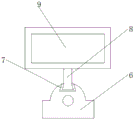
FIG. 2 is a schematic view of the connection structure of the main frame and the supporting frame of the present invention;
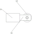
fig. 3 is a schematic view of the connection structure between the thread plate and the fixing plate of the present invention.
In the figure: 1. a manual rotating rod; 2. a first gear; 3. a second gear; 4. a threaded rod; 5. a bearing; 6. a main frame; 7. a chute; 8. a connecting rod; 9. a support frame; 10. a base; 11. a thread plate; 12. a fixing plate; 13. an electro-hydraulic lever; 14. a clamping block; 15. a protective cover; 16. a servo motor; 17. a drive belt; 18. a connecting shaft; 19. and cutting the slices.
Detailed Description
The technical solutions in the embodiments of the present invention will be described clearly and completely with reference to the accompanying drawings in the embodiments of the present invention, and it is obvious that the described embodiments are only some embodiments of the present invention, not all embodiments. Based on the embodiments in the present invention, all other embodiments obtained by a person skilled in the art without creative work belong to the protection scope of the present invention.
Referring to fig. 1-3, the present invention provides a technical solution: an English card cutting device with adjustable cutting size comprises a manual rotating rod 1, a first gear 2, a second gear 3, a threaded rod 4, a bearing 5, a main frame 6, a sliding groove 7, a connecting rod 8, a supporting frame 9, a base 10, a threaded plate 11, a fixing plate 12, an electric hydraulic rod 13, a clamping block 14, a protective cover 15, a servo motor 16, a transmission belt 17, a connecting shaft 18 and a cutting blade 19, wherein the first gear 2 is arranged on the outer side of the manual rotating rod 1, the second gear 3 is connected to the side of the first gear 2, the threaded rod 4 is connected to the left side of the second gear 3, the bearing 5 is arranged on the outer side of the threaded rod 4, the main frame 6 is arranged at the end part of the threaded rod 4, the sliding groove 7 is formed in the top of the main frame 6, the connecting rod 8 is arranged inside the sliding groove 7, the supporting frame 9 is arranged at the top of the connecting rod 8, the, the side of the supporting frame 9 is connected with a threaded plate 11, a fixing plate 12 is arranged inside the threaded plate 11, an electric hydraulic rod 13 is arranged at the bottom of the main frame 6, the side of the electric hydraulic rod 13 is connected with a clamping block 14, the bottom end of the electric hydraulic rod 13 is connected with a protective cover 15, a servo motor 16 is arranged on the left side of the protective cover 15, the end of the servo motor 16 is connected with a transmission belt 17, the inner side of the transmission belt 17 is connected with a connecting shaft 18, and a cutting blade 19 is arranged in the middle of the connecting shaft 18;
furthermore, the manual rotating rod 1 and the first gear 2 are integrally arranged, the first gear 2 and the second gear 3 are in meshed connection, a user rotates the manual rotating rod 1 according to the size required to be cut, the rotation of the manual rotating rod 1 can drive the first gear 2 and the second gear 3 to rotate, the moving distance of the main frame 6 is observed according to the number of rotating circles, the operation and the use of the device can be conveniently carried out by the user, the operation of the user is convenient and efficient, and the experience feeling is high;
furthermore, the main frame 6 and the connecting rod 8 form a sliding structure through the sliding groove 7, the main frame 6 is in threaded connection with the threaded rod 4, the threaded rod 4 is in rotational connection with the supporting frame 9 through the bearing 5, the threaded rod 4 can be driven to rotate by the rotation of the second gear 3 through the installation of the bearing 5, and due to the arrangement of the connecting rod 8 on the supporting frame 9, the main frame 6 can be driven to move left and right along the sliding groove 7, so that the position movement and the size adjustment of the cutting device can be completed, the cutting size of the cutting device can be conveniently adjusted by a user, and the cutting application range of the device can be effectively improved;
furthermore, the threaded plate 11 and the fixing plate 12 are in threaded connection, two fixing plates 12 are symmetrically arranged about the central axis of the base 10, a user can stably place a card to be cut on the top of the base 10 and rotate the fixing plate 12 on the inner side of the threaded plate 11, so that the bottom end of the fixing plate 12 presses down the English card, the English card is fixed, the user can conveniently fix the cut card, the fixing mode is simple and efficient, and the phenomenon of low qualification rate caused by the fact that the card is not neat in the cutting process can be effectively reduced;
furthermore, the protective cover 15 and the main frame 6 form a lifting structure through the electric hydraulic rod 13, the electric hydraulic rod 13 and the main frame 6 form a clamping structure through the clamping block 14, a user can finish the installation and fixation of the electric hydraulic rod 13 by aligning the clamping block 14 at the side of the electric hydraulic rod 13 to the bottom end of the main frame 6, the electric hydraulic rod 13 can drive the protective cover 15 to ascend and descend, so that the height of the cutting blade 19 can be adjusted, the automation degree of the device can be improved, and the device is convenient for the user to detach and maintain the device components;
further, the cutting piece 19 constitutes through connecting axle 18 and protection casing 15 and rotates and be connected, and connecting axle 18 constitutes chain drive structure through driving belt 17 and servo motor 16, and the user starts servo motor 16, and servo motor 16 drives driving belt 17 and connecting axle 18 and rotates, cuts the english card that has fixed, can provide support and guarantee for the cutting power of device, has promoted the fail safe nature of equipment.
The working principle is as follows: firstly, a user switches on the power supply of a servo motor 16 and an electric hydraulic rod 13, the model of the servo motor 16 is D180M-O250030C-E, the model of the electric hydraulic rod 13 is DYTZ450-/110, the user stably places a card to be cut on the top of a base 10 and rotates a fixing plate 12 on the inner side of a thread plate 11, so that the bottom end of the fixing plate 12 presses an English card down to complete the fixation of the English card, then, the user rotates a manual rotating rod 1 according to the size to be cut, the rotation of the manual rotating rod 1 can drive a first gear 2 and a second gear 3 to rotate, the moving distance of a main frame 6 is observed according to the number of rotating circles, the rotation of the second gear 3 can drive the rotation of a threaded rod 4 through the installation of a bearing 5, and the main frame 6 can move left and right along a chute 7 due to the arrangement of an engaging rod 8 on a support frame 9, thereby completing the position movement and size adjustment of the cutting device;
next, the user aims at the bottom of body frame 6 through the block 14 of the block of the avris of electronic hydraulic stem 13, accomplishes the installation and fixed to electronic hydraulic stem 13, and electronic hydraulic stem 13 can drive the rising of protection casing 15 and descend to the regulation of completion to cutting piece 19 height, and finally, the user starts servo motor 16, and servo motor 16 drives driving belt 17 and connecting axle 18 and rotates, cuts the english card that has fixed, accomplishes the operation and the use to whole cutting device.
Although embodiments of the present invention have been shown and described, it will be appreciated by those skilled in the art that changes, modifications, substitutions and alterations can be made in these embodiments without departing from the principles and spirit of the invention, the scope of which is defined in the appended claims and their equivalents.
Claims (6)
1. The utility model provides a cutting size adjustable english card cutting device, includes manual bull stick (1) and electronic hydraulic stem (13), its characterized in that: the outside of manual bull stick (1) is provided with first gear (2), and the avris of first gear (2) links up and has been connect second gear (3), the left side of second gear (3) links up and has been connected threaded rod (4), and bearing (5) are installed in the outside of threaded rod (4), and the tip of threaded rod (4) is provided with body frame (6), spout (7) have been seted up at the top of body frame (6), and the inside of spout (7) is provided with links up pole (8), the top of linking up pole (8) is provided with support frame (9), and the bottom of support frame (9) is provided with base (10), the avris of support frame (9) links up and has thread plate (11), and the internally mounted of thread plate (11) has fixed plate (12), electronic hydraulic stem (13) are installed in the bottom of body frame (6), and the avris of electronic hydraulic stem (13) links up and has been connected block (14), the bottom of electronic hydraulic stem (13) links up has protection casing (15), and installs servo motor (16) in the left side of protection casing (15), the tip of servo motor (16) links up has drive belt (17), and the inboard of drive belt (17) links up has connecting axle (18) to the mid-mounting of connecting axle (18) has cutting piece (19).
2. The english card cutting device of claim 1, wherein the cutting size is adjustable, and the device comprises: the manual rotating rod (1) and the first gear (2) are integrally arranged, and the first gear (2) and the second gear (3) are in meshed connection.
3. The english card cutting device of claim 1, wherein the cutting size is adjustable, and the device comprises: the main frame (6) forms a sliding structure with the connecting rod (8) through the sliding groove (7), the main frame (6) is in threaded connection with the threaded rod (4), and the threaded rod (4) forms a rotating connection with the support frame (9) through the bearing (5).
4. The english card cutting device of claim 1, wherein the cutting size is adjustable, and the device comprises: threaded connection is adopted between the threaded plate (11) and the fixing plate (12), and two fixing plates (12) are symmetrically arranged around the central axis of the base (10).
5. The english card cutting device of claim 1, wherein the cutting size is adjustable, and the device comprises: the protective cover (15) and the main frame (6) form a lifting structure through the electric hydraulic rod (13), and the electric hydraulic rod (13) and the main frame (6) form a clamping structure through the clamping block (14).
6. The english card cutting device of claim 1, wherein the cutting size is adjustable, and the device comprises: the cutting blade (19) is rotationally connected with the protective cover (15) through a connecting shaft (18), and the connecting shaft (18) and the servo motor (16) form a chain transmission structure through a transmission belt (17).
Priority Applications (1)
| Application Number | Priority Date | Filing Date | Title |
|---|---|---|---|
| CN202020527640.9U CN212123456U (en) | 2020-04-13 | 2020-04-13 | English card cutting device with adjustable cutting size |
Applications Claiming Priority (1)
| Application Number | Priority Date | Filing Date | Title |
|---|---|---|---|
| CN202020527640.9U CN212123456U (en) | 2020-04-13 | 2020-04-13 | English card cutting device with adjustable cutting size |
Publications (1)
| Publication Number | Publication Date |
|---|---|
| CN212123456U true CN212123456U (en) | 2020-12-11 |
Family
ID=73687382
Family Applications (1)
| Application Number | Title | Priority Date | Filing Date |
|---|---|---|---|
| CN202020527640.9U Expired - Fee Related CN212123456U (en) | 2020-04-13 | 2020-04-13 | English card cutting device with adjustable cutting size |
Country Status (1)
| Country | Link |
|---|---|
| CN (1) | CN212123456U (en) |
-
2020
- 2020-04-13 CN CN202020527640.9U patent/CN212123456U/en not_active Expired - Fee Related
Similar Documents
| Publication | Publication Date | Title |
|---|---|---|
| CN101947667A (en) | Cutting machine capable of swinging angle | |
| CN211353195U (en) | Hedge trimmer for landscaping | |
| CN205967589U (en) | Edge trimmer | |
| CN216141795U (en) | Automatic fabric production facility of cloth cutting | |
| CN204159972U (en) | A kind of metal bar cutting feed machine | |
| CN211022122U (en) | An automatic fruit peeler | |
| CN207953984U (en) | A kind of LED materials cutter device | |
| CN207284987U (en) | A kind of fully automatic cake dicer | |
| CN204811167U (en) | Mower | |
| CN112335436A (en) | Kiwi fruit branch trimming means | |
| CN202846673U (en) | Automatic prefabricated plate cutting machine | |
| CN213907604U (en) | Greening nursery stock trimming device for municipal road | |
| CN210677177U (en) | Blade sharpening device of mower | |
| CN213793698U (en) | Apple steel sheet does not have trace stamping die | |
| CN209289540U (en) | A kind of silicon carbide ceramics ingredient cutter device | |
| CN210491777U (en) | Vehicle-mounted plant trimming device | |
| CN102029492A (en) | Three-cutting torch curve groove cutting device | |
| CN211630964U (en) | Tobacco seedling leaf cutting machine | |
| CN211322160U (en) | Plant trimming device | |
| CN114080916A (en) | Multi-functional landscape trimming means | |
| CN206937022U (en) | A kind of straight line belt edge sander | |
| CN202155909U (en) | Dry type transformer coil end face cutting machine | |
| CN206276982U (en) | A kind of saw tooth cutting tool cutter spacing adjustable type crushed aggregates device | |
| CN203460256U (en) | Rotationally shearing cutter device | |
| CN223477136U (en) | A powered V-wheel automatic material receiving device suitable for slender bars |
Legal Events
| Date | Code | Title | Description |
|---|---|---|---|
| GR01 | Patent grant | ||
| GR01 | Patent grant | ||
| CF01 | Termination of patent right due to non-payment of annual fee |
Granted publication date: 20201211 Termination date: 20210413 |
|
| CF01 | Termination of patent right due to non-payment of annual fee |