CN212122463U - Clamp for machining air vent of bit leg - Google Patents
Clamp for machining air vent of bit leg Download PDFInfo
- Publication number
- CN212122463U CN212122463U CN202020807324.7U CN202020807324U CN212122463U CN 212122463 U CN212122463 U CN 212122463U CN 202020807324 U CN202020807324 U CN 202020807324U CN 212122463 U CN212122463 U CN 212122463U
- Authority
- CN
- China
- Prior art keywords
- plunger
- fixture
- bit leg
- air vent
- machining
- Prior art date
- Legal status (The legal status is an assumption and is not a legal conclusion. Google has not performed a legal analysis and makes no representation as to the accuracy of the status listed.)
- Active
Links
Images

Abstract
The utility model provides a fixture for processing air vents of bit leg, relating to a fixture, which comprises a positioning plate and a plunger, wherein the positioning plate is arranged above a plunger cavity of the plunger; the plunger is provided with a strip-shaped pulling block which is arranged in the plunger cavity in a penetrating way and moves synchronously with the plunger pulling block in the plunger wall, the outer wall of the plunger is provided with a pressing plate which is connected with the strip-shaped pulling block and is opposite to the strip-shaped pulling block in the radial direction, and the pressing plate moves synchronously with the plunger pulling block; the utility model discloses can realize that clamping, positioning accuracy are high and be connected the processing that can accomplish all air vents of bit leg with five revolving stages cooperations.
Description
Technical Field
The utility model mainly relates to a palm air vent processing technology field especially relates to an anchor clamps of processing palm air vent.
Background
The traditional processing technology for the air holes of the bit leg needs to be processed separately and needs to be divided into at least three procedures, so that multiple sets of fixtures need to be matched and clamped for multiple times, the multiple sets of fixtures are used on manual equipment, the fixture equipment adopts a common vertical drill or a rocker drill to perform manual processing, the labor cost is high, and the working precision is low.
Disclosure of Invention
The utility model discloses a overcome the not enough among the background art, the invention provides a can realize clamping once, positioning accuracy is high and with five revolving stages cooperation be connected can accomplish the anchor clamps of the gripper's of all air vents air vent.
In order to achieve the above object, the utility model provides a following technical scheme:
at least one embodiment of the present disclosure provides a fixture for processing a bit leg vent hole, including a positioning plate and a plunger, wherein the positioning plate is disposed above a plunger cavity of the plunger; the plunger is provided with a strip-shaped pulling block which penetrates through the inside of the plunger cavity and moves synchronously with the plunger pulling block in the plunger wall, the outer wall of the plunger is provided with a pressing plate which is connected with the strip-shaped pulling block and is opposite to the strip-shaped pulling block in the radial direction, and the pressing plate moves synchronously with the plunger pulling block.
For example, in the fixture for processing the air vent of the bit leg provided by at least one embodiment of the disclosure, an elastic clamping plate for performing journal positioning on a workpiece is arranged at the edge of the positioning plate.
For example, in the fixture for processing the air vent of the bit leg provided by at least one embodiment of the present disclosure, a tail supporting column for supporting a workpiece is arranged on the upper surface of the positioning plate.
For example, in the fixture for machining the air vent of the bit leg provided by at least one embodiment of the present disclosure, a thread is arranged on the outer surface of the tail supporting column to adjust the height.
For example, in the fixture for processing the air vent of the bit leg provided by at least one embodiment of the present disclosure, the elastic clamping plate and the pressing plate are arranged on opposite sides of the positioning plate.
For example, in the fixture for machining the air vent of the bit leg provided by at least one embodiment of the present disclosure, the pressing plate is an L-shaped pressing plate.
For example, in the fixture for machining the air vent of the bit leg provided by at least one embodiment of the present disclosure, an edge is arranged at the upper end of the pressing plate, and the tail of the workpiece is pressed.
For example, in the fixture for processing the air vent of the bit leg provided by at least one embodiment of the present disclosure, a positioning block is disposed below the positioning plate and at a connection position with the plunger cavity.
For example, in the fixture for processing the air vent of the bit leg provided by at least one embodiment of the present disclosure, a base is arranged below the fixture.
For example, in the fixture for machining the air hole of the bit leg provided by at least one embodiment of the disclosure, the fixture is connected with a five-axis turntable flange plate through a base.
Compared with the prior art, the beneficial effects of the utility model are that: the utility model discloses a processing bit leg air vent's anchor clamps and machining center's five revolving stages cooperation fixed connection realize the processing of bit leg air vent.
1. The utility model has high efficiency, can realize one-time clamping, and can finish the processing of all air vents of the bit leg by means of a five-axis turntable;
2. the utility model has high positioning precision, high repetition precision through shaft neck positioning, convenient establishment of a programming coordinate system and simple and convenient debugging;
3. the utility model discloses the reliability is high, adopts hydraulic system to compress tightly, and the clamping is stable.
Drawings
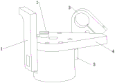
Fig. 1 is a schematic view of the overall structure of the present invention;
fig. 2 is a side sectional view of the present invention;
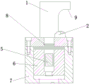
fig. 3 is a schematic sectional view of the internal structure of the present invention.
In the figure: 1-pressing plate, 2-tail supporting column, 3-elastic clamping plate, 4-positioning plate, 5-strip-shaped pulling block, 6-plunger pulling block, 7-base, 8-positioning block and 9-edge.
Detailed Description
In order to facilitate understanding of the present invention, the present invention will be described more fully with reference to the accompanying drawings, in which several embodiments of the present invention are shown, but the present invention can be implemented in different forms, and is not limited to the embodiments described in the text, but rather, these embodiments are provided to make the disclosure of the present invention more thorough and comprehensive.
It will be understood that when an element is referred to as being "secured to" another element, it can be directly on the other element or intervening elements may be present, and when an element is referred to as being "connected" to another element, it can be directly connected to the other element or intervening elements may also be present, as the terms "vertical", "horizontal", "left", "right" and the like are used herein for descriptive purposes only.
Unless defined otherwise, all technical and scientific terms used herein have the same meaning as commonly understood by one of ordinary skill in the art to which this invention belongs, and the use of the term knowledge in the specification of the present invention is for the purpose of describing particular embodiments and is not intended to limit the present invention, and the term "and/or" as used herein includes any and all combinations of one or more of the associated listed items.
Next, a fixture for machining a bit leg air vent according to at least one embodiment of the present disclosure will be described with reference to the drawings.
At least one embodiment of the present disclosure provides a fixture for processing a bit leg vent hole, as shown in fig. 1 to 3, at least one embodiment of the present disclosure provides a fixture for processing a bit leg vent hole, including a positioning plate 4 and a plunger, the positioning plate 4 being disposed above a plunger cavity of the plunger; the plunger is provided with a bar-shaped pulling block 5 which penetrates through the interior of a plunger cavity and moves synchronously with a plunger pulling block 6 in a plunger wall body, the plunger pulling block 6 is connected with a five-axis turntable oil cylinder through a screw to realize up-and-down movement, the bar-shaped pulling block 5 moves up and down along with the plunger, a pressing plate 1 connected with the bar-shaped pulling block 5 is arranged on the outer wall of the plunger at a position radially opposite to the bar-shaped pulling block 5, and the pressing plate 1 moves up and down synchronously with the plunger pulling block 6 and the plunger.
For example, in the fixture for processing the air vent of the bit leg provided in at least one embodiment of the present disclosure, as shown in fig. 1 to 2, an elastic clamping plate 3 for journaling a workpiece is provided at an edge of the positioning plate 4, and a circular hole is formed at a middle surface of the elastic clamping plate 3 for journaling the workpiece, i.e., the bit leg.
For example, in the fixture for processing the air vent of the bit leg provided by at least one embodiment of the present disclosure, as shown in fig. 1 and 3, a tail supporting column 2 for supporting a workpiece is provided on an upper surface of a positioning plate 4 to support a lower edge of a tail portion of the bit leg, and a thread is provided on an outer surface of the tail supporting column 2 to adjust a height, so as to meet requirements of different workpieces.
For example, in the fixture for processing the air vent of the bit leg provided by at least one embodiment of the present disclosure, the elastic clamping plate 3 and the pressing plate 1 are arranged on opposite sides of the positioning plate 4.
For example, in the fixture for machining the air vent of the bit leg provided by at least one embodiment of the present disclosure, as shown in fig. 1 to 3, the pressing plate 1 is an L-shaped pressing plate 1, and an edge 9 is provided at the upper end of the pressing plate 1 to press the tail of the workpiece, i.e., the bit leg.
For example, in the fixture for processing the air vent of the bit leg provided by at least one embodiment of the present disclosure, as shown in fig. 3, a positioning block 8 is disposed at a connection position of the plunger cavity and below the positioning plate 4, so as to ensure that the position of the positioning plate 4 is accurate when the fixture is installed.
For example, in the fixture for machining the air hole of the bit leg provided by at least one embodiment of the present disclosure, as shown in fig. 3, a base 7 is arranged below the fixture, and the fixture is connected with a five-axis turntable flange plate through the base 7.
Although embodiments of the present invention have been shown and described, it will be understood by those skilled in the art that various changes, modifications, substitutions and alterations can be made in these embodiments without departing from the principles and spirit of the invention, the scope of which is defined by the appended claims and their equivalents, and thus the embodiments of the invention are intended only as illustrative examples of the invention and no limitation of the invention is intended whatsoever to be construed by the embodiments of the invention.
Claims (10)
1. A clamp for processing a palm vent hole is characterized in that: the plunger positioning device comprises a positioning plate and a plunger, wherein the positioning plate is arranged above a plunger cavity of the plunger; the plunger is provided with a strip-shaped pulling block which penetrates through the inside of the plunger cavity and moves synchronously with the plunger pulling block in the plunger wall, the outer wall of the plunger is provided with a pressing plate which is connected with the strip-shaped pulling block and is opposite to the strip-shaped pulling block in the radial direction, and the pressing plate moves synchronously with the plunger pulling block.
2. The fixture for machining the air vent of the bit leg as claimed in claim 1, wherein: an elastic clamping plate for positioning the shaft neck of the workpiece is arranged at the edge of the positioning plate.
3. The fixture for machining the air vent of the bit leg as claimed in claim 1, wherein: the upper surface of the positioning plate is provided with a tail supporting column for supporting a workpiece.
4. The fixture for machining the air vent of the bit leg as claimed in claim 3, wherein: the outer surface of the tail supporting column is provided with a thread with adjustable height.
5. The fixture for machining the air vent of the bit leg as claimed in claim 2, wherein: the elastic clamping plate and the pressing plate (1) are arranged on opposite sides of the positioning plate.
6. The fixture for machining the air vent of the bit leg as claimed in claim 1, wherein: the pressing plate is an L-shaped pressing plate.
7. The fixture for machining the air vent of the bit leg as claimed in claim 6, wherein: the upper end of the pressing plate is provided with a seamed edge for pressing the tail part of the workpiece.
8. The fixture for machining the air vent of the bit leg as claimed in claim 1, wherein: and a positioning block is arranged at the joint of the lower part of the positioning plate and the plunger cavity.
9. The fixture for machining the air vent of the bit leg as claimed in claim 1, wherein: a base is arranged below the clamp.
10. The fixture for machining the air vent of the bit leg as claimed in claim 9, wherein: the fixture is connected with the five-axis turntable flange plate through the base.
Priority Applications (1)
| Application Number | Priority Date | Filing Date | Title |
|---|---|---|---|
| CN202020807324.7U CN212122463U (en) | 2020-05-15 | 2020-05-15 | Clamp for machining air vent of bit leg |
Applications Claiming Priority (1)
| Application Number | Priority Date | Filing Date | Title |
|---|---|---|---|
| CN202020807324.7U CN212122463U (en) | 2020-05-15 | 2020-05-15 | Clamp for machining air vent of bit leg |
Publications (1)
| Publication Number | Publication Date |
|---|---|
| CN212122463U true CN212122463U (en) | 2020-12-11 |
Family
ID=73694433
Family Applications (1)
| Application Number | Title | Priority Date | Filing Date |
|---|---|---|---|
| CN202020807324.7U Active CN212122463U (en) | 2020-05-15 | 2020-05-15 | Clamp for machining air vent of bit leg |
Country Status (1)
| Country | Link |
|---|---|
| CN (1) | CN212122463U (en) |
-
2020
- 2020-05-15 CN CN202020807324.7U patent/CN212122463U/en active Active
Similar Documents
| Publication | Publication Date | Title |
|---|---|---|
| CN207372737U (en) | The flexible fast replacing device of harmonic reducer of robot | |
| CN204248507U (en) | The fixture of processing automobile gearbox balancing weight | |
| CN203993176U (en) | A kind of wedge-type centering and clamping mechanism | |
| CN212122463U (en) | Clamp for machining air vent of bit leg | |
| CN210115629U (en) | Positioning fixture for sheet metal parts | |
| CN208543242U (en) | A kind of Machining of Shaft-type Parts positioning fixture | |
| CN208514124U (en) | The positioning fixture positioned to workpiece and the numerically-controlled machine tool including the positioning fixture | |
| CN207630056U (en) | A kind of improved rotor gripper structure | |
| CN206105738U (en) | Rubber bush location of high accuracy is hung auris pressure and is gone into device | |
| CN212240040U (en) | Special milling fixture for weak-rigidity slice part | |
| CN108907587B (en) | Flexible welding fixture for automobile parts | |
| CN203484949U (en) | Four-point clamping fixture | |
| CN107598232B (en) | Drilling method and drilling fixture for rotary part | |
| CN206154146U (en) | Return bend typing anchor clamps | |
| CN112823984A (en) | Fixture for drilling L-shaped part and using method | |
| CN214602331U (en) | Reducing internal spline gear shaping clamp | |
| CN110434372A (en) | A kind of thin plate drilling tool fixture and its clamping method | |
| CN211727616U (en) | Tool capable of being provided with small eccentric hole and small hole | |
| CN208681033U (en) | A kind of truning fixture for light rail support cam | |
| CN210255192U (en) | Special tool for machining valve block | |
| CN208744221U (en) | A kind of adjustable computer gong 3D fixture | |
| CN211102816U (en) | Valve seat ring processing tool | |
| CN210209562U (en) | Gyration type part compresses tightly frock | |
| CN210499791U (en) | Split clamping jaw | |
| CN109551272B (en) | Radial centering combined clamping fixture positioned by conical pin and application method thereof |
Legal Events
| Date | Code | Title | Description |
|---|---|---|---|
| GR01 | Patent grant | ||
| GR01 | Patent grant |