CN212109340U - Drying device is used in iron oxide production that facilitates use - Google Patents
Drying device is used in iron oxide production that facilitates use Download PDFInfo
- Publication number
- CN212109340U CN212109340U CN202020666890.0U CN202020666890U CN212109340U CN 212109340 U CN212109340 U CN 212109340U CN 202020666890 U CN202020666890 U CN 202020666890U CN 212109340 U CN212109340 U CN 212109340U
- Authority
- CN
- China
- Prior art keywords
- iron oxide
- drying box
- top surface
- drying
- mounting frame
- Prior art date
- Legal status (The legal status is an assumption and is not a legal conclusion. Google has not performed a legal analysis and makes no representation as to the accuracy of the status listed.)
- Expired - Fee Related
Links
Images


Landscapes
- Drying Of Solid Materials (AREA)
Abstract
本实用新型公开了一种方便使用的氧化铁生产用干燥装置,包括干燥箱体,所述干燥箱体内壁均固接有分隔漏斗,分隔漏斗内部均设有加热管,所述干燥箱体上下端内壁通过滚动轴承转动连接有空心杆,所述干燥箱体外顶面还通过螺钉固接有安装架,安装架顶面一侧通过螺钉固接有伺服电机一,伺服电机一的输出端穿过安装架顶面并与空心杆外壁通过齿轮组转动连接,所述安装架顶面另一侧通过螺钉固接有伺服电机二,伺服电机二的输出端穿过安装架顶面并固接有转杆,所述转杆下端延伸至空心杆下侧。本实用新型采用分层干燥的方法对氧化铁进行干燥,其干燥效果好,效率高,为氧化铁快速生产提供了一定的保障。
The utility model discloses an easy-to-use drying device for iron oxide production, comprising a drying box body, a partition funnel is fixedly connected to the inner wall of the drying box, a heating pipe is arranged inside the partition funnel, and the upper and lower sides of the drying box body are The inner wall of the end is rotatably connected with a hollow rod through a rolling bearing, the outer top surface of the drying box is also fixed with a mounting frame by screws, and a servo motor one is fixed on one side of the top surface of the mounting frame by screws, and the output end of the servo motor one passes through The top surface of the mounting frame is connected with the outer wall of the hollow rod through a gear set in rotation, the other side of the top surface of the mounting frame is fixed with a second servo motor through screws, and the output end of the second servo motor passes through the top surface of the mounting frame and is fixed with a rotating A rod, the lower end of the rotating rod extends to the lower side of the hollow rod. The utility model adopts the layered drying method to dry the iron oxide, which has good drying effect and high efficiency, and provides a certain guarantee for the rapid production of the iron oxide.
Description
技术领域technical field
本实用新型涉及氧化铁生产设备技术领域,尤其涉及一种方便使用的氧化铁生产用干燥装置。The utility model relates to the technical field of iron oxide production equipment, in particular to a convenient-to-use drying device for iron oxide production.
背景技术Background technique
氧化铁具有耐光、耐高温等性能,要用于彩色水泥、涂料着色、保护物质、塑料制品的着色和高级精磨材料,在氧化铁生产时常需要对其进行干燥,这就要用到干燥设备。Iron oxide has properties such as light resistance and high temperature resistance. It is used for color cement, paint coloring, protective material, coloring of plastic products and advanced grinding materials. It is often necessary to dry iron oxide during production, which requires drying equipment. .
经检索,申请号201821792437.3的专利,公开一种便于调节干燥体积的氧化铁红干燥机,包括干燥机主体、移动板、凸缘和第二滑道,干燥机主体内底部设置有电机,且电机上设置有电机轴,同时电机轴贯穿隔板,隔板设置在干燥机主体内侧壁上,且隔板设置在电机上方,干燥机主体前后侧壁均设置有第一加热板、第二加热板和第三加热板,且第一加热板设置在第二加热板左侧,同时第二加热板设置在第三加热板左侧,第一加热板、第二加热板和第三加热板均设置在隔板上方,且隔板上端设置有转盘,同时转盘下端与电机轴相连接,移动板设置在干燥机主体内,且移动板上端卡合在第一滑道内,第一滑道设置在干燥机主体侧壁上,且第一滑道设置在第一加热板上方,凸缘设置在移动板外侧面,且凸缘上贯穿有螺栓,同时移动板通过螺栓固定在隔板上。After retrieval, the patent with the application number 201821792437.3 discloses an iron oxide red dryer that is easy to adjust the drying volume, including a dryer body, a moving plate, a flange and a second slideway. There is a motor shaft on the top, and the motor shaft penetrates through the partition plate, the partition plate is arranged on the inner side wall of the dryer main body, and the partition plate is arranged above the motor, and the front and rear side walls of the dryer main body are provided with a first heating plate and a second heating plate. and the third heating plate, and the first heating plate is arranged on the left side of the second heating plate, while the second heating plate is arranged on the left side of the third heating plate, the first heating plate, the second heating plate and the third heating plate are all arranged Above the partition, and the upper end of the partition is provided with a turntable, and the lower end of the turntable is connected with the motor shaft, the moving plate is arranged in the main body of the dryer, and the upper end of the moving plate is engaged in the first slideway, and the first slideway is arranged in the drying machine. On the side wall of the main body, and the first slideway is arranged above the first heating plate, the flange is arranged on the outer side of the moving plate, and bolts pass through the flange, and the moving plate is fixed on the partition plate by bolts.
上述装置在使用时氧化铁堆积在容器内导致其中心位置难以受热,且干燥时水分蒸发受阻,严重影响了氧化铁干燥的效率,难以满足快速生产的需求,所以研究一种方便使用的氧化铁生产用干燥装置是很有必要的。When the above-mentioned device is in use, the iron oxide is accumulated in the container, which makes it difficult to heat its center position, and the evaporation of water is hindered during drying, which seriously affects the drying efficiency of iron oxide, and it is difficult to meet the needs of rapid production. Therefore, a convenient iron oxide is studied. Production drying equipment is necessary.
实用新型内容Utility model content
本实用新型的目的是为了解决现有技术中存在的缺点,而提出的一种方便使用的氧化铁生产用干燥装置。The purpose of this utility model is to solve the shortcomings existing in the prior art, and propose a drying device for iron oxide production that is convenient to use.
为了实现上述目的,本实用新型采用了如下技术方案:In order to achieve the above-mentioned purpose, the utility model adopts the following technical solutions:
一种方便使用的氧化铁生产用干燥装置,包括干燥箱体,所述干燥箱体内壁均固接有分隔漏斗,分隔漏斗内部均设有加热管,所述干燥箱体上下端内壁通过滚动轴承转动连接有空心杆,所述干燥箱体外顶面还通过螺钉固接有安装架,安装架顶面一侧通过螺钉固接有伺服电机一,伺服电机一的输出端穿过安装架顶面并与空心杆外壁通过齿轮组转动连接,所述安装架顶面另一侧通过螺钉固接有伺服电机二,伺服电机二的输出端穿过安装架顶面并固接有转杆,所述转杆下端延伸至空心杆下侧,所述转杆外壁还通过螺钉固接有堵塞块,所述堵塞块的前后端均开设有通料孔,所述空心杆两侧还开设有通孔,所述干燥箱体上部两侧均设有排气管,排气管靠近干燥箱体一侧均贯通连接有吸气管,所述吸气管一端均穿过干燥箱体侧壁并在端部固接有隔尘罩,所述干燥箱体底端两侧均设置有安装台,安装台顶面通过螺钉固接有气泵,所述气泵输入端与排气管之间贯通连接有吸尘管,气泵的输出端均固接有出气管,所述空心杆外壁还固接有搅拌浆,所述干燥箱体前后端均贯穿连接有投料斗,所述干燥箱体底部还设有收集皿。An easy-to-use drying device for iron oxide production, comprising a drying box, the inner wall of the drying box is fixedly connected with a partition funnel, and a heating pipe is arranged inside the partition funnel, and the inner walls of the upper and lower ends of the drying box are rotated by rolling bearings. A hollow rod is connected, an installation frame is also fixed on the outer top surface of the drying box through screws, a servo motor 1 is fixed on one side of the top surface of the installation frame through screws, and the output end of the servo motor 1 passes through the top surface of the installation frame and is It is rotatably connected with the outer wall of the hollow rod through a gear set. The other side of the top surface of the mounting frame is fixed with a second servo motor through screws. The output end of the second servo motor passes through the top surface of the mounting frame and is fixed with a rotating rod. The lower end of the rod extends to the lower side of the hollow rod, and the outer wall of the rotating rod is also fixed with a blocking block through screws. The front and rear ends of the blocking block are provided with through holes, and the two sides of the hollow rod are also provided with through holes, so There are exhaust pipes on both sides of the upper part of the drying box. The exhaust pipes are connected with suction pipes on one side close to the drying box. One end of the suction pipes passes through the side walls of the drying box and is fixed at the end. A dust cover is connected, and installation platforms are arranged on both sides of the bottom end of the drying box. The top surface of the installation platform is fixedly connected with an air pump through screws. The output end of the air pump is fixed with an air outlet pipe, the outer wall of the hollow rod is also fixed with a stirring slurry, the front and rear ends of the drying box are connected with a feeding hopper, and the bottom of the drying box is also provided with a collection dish.
优选的,所述空心杆底部内部固接有固定环,固定环内侧设有固定柱,所述转杆通过滚动轴承固接在固定柱上,所述固定环与固定柱之间还连接有连接片,且连接片设有多个并均匀分布在固定环与固定柱之间。Preferably, a fixing ring is fixed inside the bottom of the hollow rod, a fixing column is arranged on the inner side of the fixing ring, the rotating rod is fixed on the fixing column through a rolling bearing, and a connecting piece is also connected between the fixing ring and the fixing column , and the connecting piece is provided with a plurality of and evenly distributed between the fixing ring and the fixing column.
优选的,所述分隔漏斗设有多个并均匀分布在干燥箱体内壁上,搅拌浆的数量与分隔漏斗数量一致并均位于分隔漏斗上侧位置。Preferably, a plurality of the separating funnels are provided and are evenly distributed on the inner wall of the drying box, and the number of stirring slurries is consistent with the number of separating funnels and both are located on the upper side of the separating funnels.
优选的,所述吸气管的数量均与分隔漏斗数量一致,吸气管均朝上倾斜设置,所述吸气管与水平方向上所夹锐角为18°。Preferably, the number of the suction pipes is the same as the number of the separating funnels, the suction pipes are inclined upward, and the acute angle between the suction pipes and the horizontal direction is 18°.
优选的,所述空心杆与分隔漏斗滑动接触连接,且堵塞块与空心杆内壁贴合。Preferably, the hollow rod is connected in sliding contact with the separating funnel, and the blocking block is attached to the inner wall of the hollow rod.
优选的,所述投料斗的数量与分隔漏斗数量一致并交错设置在干燥箱体前后端位置。Preferably, the number of the feeding hoppers is the same as the number of the separating funnels, and is staggered at the front and rear ends of the drying box.
优选的,所述堵塞块顶端均呈漏斗状设置,且通孔上下端均贯穿堵塞块。Preferably, the top of the blocking block is arranged in a funnel shape, and the upper and lower ends of the through hole pass through the blocking block.
与现有技术相比,本实用新型的有益效果是:Compared with the prior art, the beneficial effects of the present utility model are:
1、本实用新型采用分层干燥的方法对氧化铁进行干燥,其干燥效果好,效率高,为氧化铁快速生产提供了一定的保障;1. The utility model adopts the method of layered drying to dry the iron oxide, and its drying effect is good and the efficiency is high, which provides a certain guarantee for the rapid production of iron oxide;
2、本实用新型在使用时通过伺服电机一带动空心杆从而实现搅拌浆对氧化铁进行搅拌,从而增快了氧化铁中水分的散发,且在气泵作用下能实现水蒸气快速吸出,大大提高了氧化铁的干燥效率;2. When the utility model is in use, the hollow rod is driven by the servo motor to realize the stirring of the iron oxide by the stirring slurry, so as to speed up the emission of water in the iron oxide, and the water vapor can be quickly sucked out under the action of the air pump, greatly improving improve the drying efficiency of iron oxide;
3、本实用新型在干燥时,伺服电机二带动转杆与空心杆同步转动,从而使堵塞块将通孔实现密封,避免氧化铁从通孔中流出,在完成氧化铁烘干后,通过伺服电机二再带动堵塞块旋转90°,从而使氧化铁从通孔滑入空心杆内,进而实现氧化铁的卸料作业,操作简便,大大提高了氧化铁烘干的效率;3. When the utility model is drying, the second servo motor drives the rotating rod and the hollow rod to rotate synchronously, so that the blocking block seals the through hole and prevents the iron oxide from flowing out of the through hole. The second motor drives the blocking block to rotate 90°, so that the iron oxide slides into the hollow rod from the through hole, thereby realizing the unloading operation of the iron oxide, which is easy to operate and greatly improves the drying efficiency of the iron oxide;
4、本实用新型通过在转杆底端转动连接有固定柱,且固定柱外侧设有固定环,固定柱与之间均匀连接有多个连接片,从而使转杆转动时更加平稳,大大调高了装置运行的稳定性。4. In the present invention, a fixed column is rotatably connected to the bottom end of the rotating rod, and the outer side of the fixed column is provided with a fixed ring, and a plurality of connecting pieces are evenly connected between the fixed column and the fixed column, so that the rotating rod is more stable and greatly adjusted. Improve the stability of the device operation.
附图说明Description of drawings
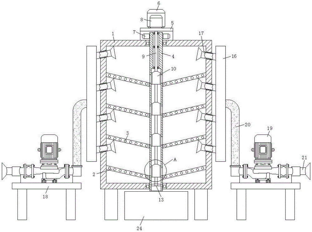
图1为本实用新型提出的一种方便使用的氧化铁生产用干燥装置的正面剖视图;Fig. 1 is the front sectional view of a kind of convenient iron oxide production drying device proposed by the utility model;
图2为本实用新型提出的一种方便使用的氧化铁生产用干燥装置的侧面剖视图;Fig. 2 is the side sectional view of a kind of convenient iron oxide production drying device proposed by the utility model;
图3为本实用新型提出的一种方便使用的氧化铁生产用干燥装置图1中A处放大图;Fig. 3 is an enlarged view of place A in Fig. 1 of a kind of convenient to use drying device for iron oxide production proposed by the utility model;
图4为本实用新型提出的一种方便使用的氧化铁生产用干燥装置中堵塞块的结构示意图;Fig. 4 is the structural representation of blockage block in a kind of convenient to use drying device for iron oxide production proposed by the utility model;
图5为本实用新型提出的一种方便使用的氧化铁生产用干燥装置中。Figure 5 is a convenient drying device for iron oxide production proposed by the utility model.
图中:干燥箱体1、分隔漏斗2、加热管3、空心杆4、安装架5、伺服电机一6、齿轮组7、伺服电机二8、转杆9、堵塞块10、通料孔11、通孔12、固定环13、固定柱14、连接片15、排气管16、吸气管17、安装台18、气泵19、吸尘管20、出气管21、搅拌浆22、投料斗23。In the figure: drying box 1, separating
具体实施方式Detailed ways
下面将结合本实用新型实施例中的附图,对本实用新型实施例中的技术方案进行清楚、完整地描述,显然,所描述的实施例仅仅是本实用新型一部分实施例,而不是全部的实施例。The technical solutions in the embodiments of the present utility model will be clearly and completely described below with reference to the accompanying drawings in the embodiments of the present utility model. Obviously, the described embodiments are only a part of the embodiments of the present utility model, rather than all the implementations. example.
实施例一Example 1
参照图1-4,一种方便使用的氧化铁生产用干燥装置,包括干燥箱体1,干燥箱体1内壁均固接有分隔漏斗2,分隔漏斗2内部均设有加热管3,干燥箱体1上下端内壁通过滚动轴承转动连接有空心杆4,干燥箱体1外顶面还通过螺钉固接有安装架5,安装架5顶面一侧通过螺钉固接有伺服电机一6,伺服电机一6的输出端穿过安装架5顶面并与空心杆4外壁通过齿轮组7转动连接,安装架5顶面另一侧通过螺钉固接有伺服电机二8,伺服电机二8的输出端穿过安装架5顶面并固接有转杆9,转杆9下端延伸至空心杆4下侧,转杆9与空心杆4内壁不接触,转杆9外壁还通过螺钉固接有堵塞块10,堵塞块10的前后端均开设有通料孔11,空心杆4两侧还开设有通孔12,堵塞块10两侧堵塞通孔12,从而使氧化铁在干燥时不会掉落至空心杆4内,干燥箱体1上部两侧均设有排气管16,排气管16靠近干燥箱体1一侧均贯通连接有吸气管17,吸气管17一端均穿过干燥箱体1侧壁并在端部固接有隔尘罩,从而避免氧化铁被吸出,干燥箱体1底端两侧均设置有安装台18,安装台18顶面通过螺钉固接有气泵19,气泵19输入端与排气管16之间贯通连接有吸尘管20,气泵19的输出端均固接有出气管21,空心杆4外壁还固接有搅拌浆22,干燥箱体1前后端均贯穿连接有投料斗23,干燥箱体1底部还设有收集皿24。1-4, a drying device for iron oxide production that is convenient to use, includes a drying box 1, the inner wall of the drying box 1 is fixed with a
分隔漏斗2设有多个并均匀分布在干燥箱体1内壁上,搅拌浆22的数量与分隔漏斗2数量一致并均位于分隔漏斗2上侧位置,从而实现氧化铁分层干燥的效果,实现氧化铁的快速干燥。There are a plurality of separating
吸气管17的数量均与分隔漏斗2数量一致,吸气管17均朝上倾斜设置,吸气管17与水平方向上所夹锐角为18°,避免氧化铁被吸出,保证氧化铁烘干的出品率。The number of the
空心杆4与分隔漏斗2滑动接触连接,且堵塞块10与空心杆4内壁贴合,从而实现氧化铁的堵塞,避免未进行烘干的氧化铁从空心柱4掉出,投料斗23的数量与分隔漏斗2数量一致并交错设置在干燥箱体1前后端位置,从而使上料更便捷。The
堵塞块10顶端均呈漏斗状设置,且通孔12上下端均贯穿堵塞块10,通孔12底面由干燥箱体1外侧向内侧朝下倾斜设置,且通孔12均与分隔漏斗2交接处齐平,从而使烘干后的氧化铁能顺利落入空心柱4内,保证氧化铁能全部从空心柱4中滑出。The top of the blocking
在使用时,首先将氧化铁通过投料斗23投放至干燥箱体1内,然后将加热管3接通电源并启动伺服电机一6和伺服电机二8,伺服电机一6和伺服电机二8带动空心杆4和转杆9同步转动,此时搅拌浆22实现对氧化铁的搅拌,在气泵19作用下能实现水蒸气快速吸出,干燥完成后,伺服电机二8再带动堵塞块10旋转90度,从而使氧化铁从通孔滑入空心杆4并落入收集皿24内。When in use, the iron oxide is first put into the drying box 1 through the
实施例二
参照图1和5,本实施例与实施例一基本相同,更优选的在于,空心杆4底部内部固接有固定环13,固定环13内侧设有固定柱14,转杆9通过滚动轴承固接在固定柱上,固定环13与固定柱14之间还连接有连接片15,且连接片15设有多个并均匀分布在固定环13与固定柱14之间,从而使转杆9转动时更加平稳,大大调高了装置运行的稳定性。1 and 5, the present embodiment is basically the same as the first embodiment, more preferably, a fixed
以上,仅为本实用新型较佳的具体实施方式,但本实用新型的保护范围并不局限于此,任何熟悉本技术领域的技术人员在本实用新型揭露的技术范围内,根据本实用新型的技术方案及其实用新型构思加以等同替换或改变,都应涵盖在本实用新型的保护范围之内。The above are only the preferred specific embodiments of the present invention, but the protection scope of the present invention is not limited thereto. Equivalent replacement or modification of the technical solution and its utility model concept shall be included within the protection scope of the present utility model.
Claims (7)
Priority Applications (1)
| Application Number | Priority Date | Filing Date | Title |
|---|---|---|---|
| CN202020666890.0U CN212109340U (en) | 2020-04-28 | 2020-04-28 | Drying device is used in iron oxide production that facilitates use |
Applications Claiming Priority (1)
| Application Number | Priority Date | Filing Date | Title |
|---|---|---|---|
| CN202020666890.0U CN212109340U (en) | 2020-04-28 | 2020-04-28 | Drying device is used in iron oxide production that facilitates use |
Publications (1)
| Publication Number | Publication Date |
|---|---|
| CN212109340U true CN212109340U (en) | 2020-12-08 |
Family
ID=73617903
Family Applications (1)
| Application Number | Title | Priority Date | Filing Date |
|---|---|---|---|
| CN202020666890.0U Expired - Fee Related CN212109340U (en) | 2020-04-28 | 2020-04-28 | Drying device is used in iron oxide production that facilitates use |
Country Status (1)
| Country | Link |
|---|---|
| CN (1) | CN212109340U (en) |
-
2020
- 2020-04-28 CN CN202020666890.0U patent/CN212109340U/en not_active Expired - Fee Related
Similar Documents
| Publication | Publication Date | Title |
|---|---|---|
| CN206291667U (en) | A kind of vertical grain drying device for preventing overfeeding | |
| CN106733006A (en) | A kind of air convection crushing equipment with primary crushing function | |
| CN218269823U (en) | Rotary flash dryer | |
| CN206285821U (en) | A kind of powdered chemical raw material mixing device | |
| CN209552128U (en) | Mixing tank for block production | |
| CN206983038U (en) | plastic grain dryer | |
| CN219037455U (en) | Paddle dryer | |
| CN111059880A (en) | A kind of melon seed heat treatment integrated device and processing method thereof | |
| CN216499708U (en) | Hardened broiler chicken feed loosening machine | |
| CN209471043U (en) | A Grain Moisture Detection Device Based on Electromagnetic Waves | |
| CN220062323U (en) | Starch drying device | |
| CN221324973U (en) | Dryer with guide structure | |
| CN208891604U (en) | A kind of paddy mechanical drying device | |
| CN111795556A (en) | A uniform drying device for raw materials used in the manufacture of anti-corrosion coatings | |
| CN207416063U (en) | A kind of construction material drying and moulding equipment | |
| CN218049346U (en) | Shell cleaning equipment with drying function | |
| CN215930441U (en) | Grain drying bin | |
| CN213811511U (en) | Horizontal paddle dryer | |
| CN214634039U (en) | A kind of coating preparation dehydration equipment | |
| CN113786758A (en) | Raw material mixing device is used in fertilizer processing | |
| CN209955075U (en) | A raw material crushing device for plastic processing | |
| CN203908258U (en) | Agitated dryer | |
| CN208653131U (en) | A kind of construction site sand drying unit | |
| CN209300140U (en) | A kind of hot air circulation drying oven pile fermentation equipment of dark green tea processing | |
| CN208238454U (en) | Cleaning drying integral machine is used in a kind of production of desiccant |
Legal Events
| Date | Code | Title | Description |
|---|---|---|---|
| GR01 | Patent grant | ||
| GR01 | Patent grant | ||
| TR01 | Transfer of patent right | ||
| TR01 | Transfer of patent right |
Effective date of registration: 20230707 Address after: No. 4-1-07, Floor 1, Unit 4, Building 1, Phase I, Beiyingjun Residential Community B, Baihe Road, West Side of Jianshe South Street, Pingdingbao Town, Guyuan County, Zhangjiakou City, Hebei Province 076500 Patentee after: Hebei Dalianmao Machinery Manufacturing Co.,Ltd. Address before: 244000 building 3, Lianmeng village, Wusong Town, Tongguan District, Tongling City, Anhui Province Patentee before: Tongling tongdaxing Industrial Co.,Ltd. |
|
| EE01 | Entry into force of recordation of patent licensing contract | ||
| EE01 | Entry into force of recordation of patent licensing contract |
Assignee: Zhangjiakou Senshuo Technology Co.,Ltd. Assignor: Hebei Dalianmao Machinery Manufacturing Co.,Ltd. Contract record no.: X2023980044746 Denomination of utility model: A Convenient Drying Device for Iron Oxide Production Granted publication date: 20201208 License type: Common License Record date: 20231026 |
|
| TR01 | Transfer of patent right | ||
| TR01 | Transfer of patent right |
Effective date of registration: 20240822 Address after: 055450 Industrial Zone, Baixiang County, Xingtai City, Hebei Province Patentee after: HEBEI GENDUOSHOU FERTILIZER Co.,Ltd. Country or region after: China Address before: No. 4-1-07, Floor 1, Unit 4, Building 1, Phase I, Beiyingjun Residential Community B, Baihe Road, West Side of Jianshe South Street, Pingdingbao Town, Guyuan County, Zhangjiakou City, Hebei Province 076500 Patentee before: Hebei Dalianmao Machinery Manufacturing Co.,Ltd. Country or region before: China |
|
| CF01 | Termination of patent right due to non-payment of annual fee | ||
| CF01 | Termination of patent right due to non-payment of annual fee |
Granted publication date: 20201208 |