CN212107073U - Ultra high pressure back pressure valve - Google Patents
Ultra high pressure back pressure valve Download PDFInfo
- Publication number
- CN212107073U CN212107073U CN202020800941.4U CN202020800941U CN212107073U CN 212107073 U CN212107073 U CN 212107073U CN 202020800941 U CN202020800941 U CN 202020800941U CN 212107073 U CN212107073 U CN 212107073U
- Authority
- CN
- China
- Prior art keywords
- valve
- joint
- wall
- valve body
- pressure
- Prior art date
- Legal status (The legal status is an assumption and is not a legal conclusion. Google has not performed a legal analysis and makes no representation as to the accuracy of the status listed.)
- Expired - Fee Related
Links
Images


Landscapes
- Taps Or Cocks (AREA)
Abstract
本实用新型公开了超高压回压阀,涉及超高压阀技术领域,为解决现有技术的超高压回压阀因其结构原因,导致的压力平衡性较弱,波动较大,敏感度低,无法迅速提供稳定回压压力等的问题。所述阀体的下端设置有下座,所述下座的内部设置有阀堵,所述阀堵的下方设置有下接头与阀堵的连接处设置有直角组合密封件,所述下接头的外壁上设置有锁紧螺母,所述锁紧螺帽的上方设置有第一压帽和压垫,所述下座的一侧外壁上设置有连接头,所述阀体的上端设置有上接头,所述上接头的外壁上设置有压紧螺母,所述上接头的下端设置有活塞,所述活塞的内部设置有阀针,所述阀体的一侧外壁上设置有加长压盖。
The utility model discloses an ultra-high pressure back pressure valve, which relates to the technical field of ultra-high pressure valves. In order to solve the structural reasons of the ultra-high pressure back pressure valve in the prior art, the pressure balance is weak, the fluctuation is large, and the sensitivity is low. Problems such as the inability to quickly provide stable back pressure. The lower end of the valve body is provided with a lower seat, the inside of the lower seat is provided with a valve plug, the lower part of the valve plug is provided with a right-angle combined seal at the connection between the lower joint and the valve plug, and the lower joint is provided with a right-angle combined seal. A locking nut is arranged on the outer wall, a first pressure cap and a pressure pad are arranged above the locking nut, a connecting head is arranged on the outer wall of one side of the lower seat, and an upper joint is arranged on the upper end of the valve body A compression nut is arranged on the outer wall of the upper joint, a piston is arranged at the lower end of the upper joint, a valve needle is arranged inside the piston, and an extension gland is arranged on the outer wall of one side of the valve body.
Description
技术领域technical field
本实用新型涉及超高压阀技术领域,具体为超高压回压阀。The utility model relates to the technical field of ultra-high pressure valves, in particular to an ultra-high pressure back pressure valve.
背景技术Background technique
阀是利用一个活动部件来开、关或部分地挡住一个或更多的开口或通道,使液流、空气流或其他气流可以流出、堵住或得到调节的一种装置;所谓阀芯,为阀体中的活动部件,当超高压阀工作压力等于或高于98.1MPa,一般通径范围为3~40mm,操作温度≤300℃,结构上采用锥面密封以提高密封性和减少阀杆受力;采用升降式阀杆以防止密封面擦伤;用氟塑料成型填料与金属组合的阀杆密封结构,主要受力件用高强度、高韧性、高质量的低合金钢制成,适用于石油、化工以及其它液压输送管路中,作为设备的超压保护装置。A valve is a device that uses a moving part to open, close or partially block one or more openings or passages, so that liquid, air or other air flows can flow out, block or be regulated; the so-called valve core is a The moving parts in the valve body, when the working pressure of the ultra-high pressure valve is equal to or higher than 98.1MPa, the general diameter range is 3~40mm, and the operating temperature is ≤300℃. Lifting valve stem is used to prevent the sealing surface from being scratched; the valve stem sealing structure is composed of fluoroplastic molding packing and metal, and the main force-bearing parts are made of high-strength, high-toughness, high-quality low-alloy steel, suitable for In petroleum, chemical and other hydraulic pipelines, it is used as an overpressure protection device for equipment.
现有的超高压回压阀因其结构原因,导致其压力平衡性较弱,波动较大,敏感度低,无法迅速提供稳定的回压压力等问题,因此,急需提供一种能够解决上述技术问题的超高压回压阀。Due to the structure of the existing ultra-high pressure back pressure valve, its pressure balance is weak, the fluctuation is large, the sensitivity is low, and it cannot quickly provide a stable back pressure pressure. Therefore, it is urgent to provide a technology that can solve the above problems. Problem with the ultra-high pressure back pressure valve.
实用新型内容Utility model content
本实用新型的目的在于提供一种超高压回压阀,用以解决现有的超高压回压阀因其结构原因,导致其压力平衡性较弱,波动较大,敏感度低,无法迅速提供稳定的回压压力等的技术问题。The purpose of this utility model is to provide an ultra-high pressure back pressure valve, which is used to solve the problem that the existing ultra-high pressure back pressure valve has weak pressure balance, large fluctuation and low sensitivity due to its structural reasons, and cannot be quickly provided. Technical issues such as stable back pressure.
为实现上述目的,本实用新型提供如下技术方案:超高压回压阀,包括阀体,所述阀体的下端设置有下座,所述下座的内部设置有阀堵,所述阀堵的下方设置有下接头与阀堵的连接处设置有直角组合密封件,所述下接头的外壁上设置有锁紧螺母,所述锁紧螺母的上方设置有第一压帽和压垫,所述下座的一侧外壁上设置有连接头,所述阀体的上端设置有上接头,所述上接头的外壁上设置有压紧螺母,所述上接头的下端设置有活塞,所述活塞的内部设置有阀针,所述阀体的一侧外壁上设置有加长压盖,所述加长压盖的内部设置有管线,所述管线的一端通过管线螺母套与加长压盖的内部固定连接。In order to achieve the above purpose, the present invention provides the following technical solutions: an ultra-high pressure back pressure valve, including a valve body, a lower seat is arranged at the lower end of the valve body, a valve plug is arranged inside the lower seat, and the valve plug is The lower part is provided with a right-angle combined seal at the connection between the lower joint and the valve plug, a locking nut is arranged on the outer wall of the lower joint, and a first pressure cap and a pressure pad are arranged above the locking nut. A connecting head is arranged on the outer wall of one side of the lower seat, an upper joint is arranged on the upper end of the valve body, a compression nut is arranged on the outer wall of the upper joint, and a piston is arranged at the lower end of the upper joint. A valve needle is arranged inside, an extension gland is arranged on one outer wall of the valve body, a pipeline is arranged inside the extension gland, and one end of the pipeline is fixedly connected to the inside of the extension gland through a pipeline nut sleeve.
优选的,所述下接头的内部两侧外壁上设置有连接孔,所述下接头的内部设置有阀板安装孔,且阀板安装孔与两个连接孔均位于同一水平线上,所述连接孔和阀板安装孔的内部设置有固定杆。Preferably, connecting holes are provided on the inner two outer walls of the lower joint, a valve plate mounting hole is arranged inside the lower joint, and the valve plate mounting hole and the two connecting holes are located on the same horizontal line. A fixing rod is arranged inside the hole and the valve plate mounting hole.
优选的,所述固定杆的两端均设置有螺纹段,且螺纹段的外壁上安装有锁紧螺帽,所述螺纹段的下端安装有密封垫圈,且密封垫圈与连接孔的外壁紧密贴合。Preferably, both ends of the fixing rod are provided with threaded sections, the outer wall of the threaded section is provided with a locking nut, the lower end of the threaded section is provided with a sealing washer, and the sealing washer is in close contact with the outer wall of the connecting hole combine.
优选的,所述固定杆的一端设置有顶板,所述顶板的一侧设置有拉环,且拉环下端的托板通过转轴与顶板转动连接。Preferably, one end of the fixing rod is provided with a top plate, one side of the top plate is provided with a pull ring, and the support plate at the lower end of the pull ring is rotatably connected to the top plate through a rotating shaft.
优选的,所述上接头与阀体的连接处设置有第二压帽和垫片,且垫片位于第二压帽的下方,所述垫片与阀体的内部机械密封连接。Preferably, a second pressure cap and a gasket are provided at the connection between the upper joint and the valve body, the gasket is located below the second pressure cap, and the gasket is connected to the internal mechanical seal of the valve body.
优选的,所述下接头和上接头的分别位于阀体的下端和上端,且下接头和上接头的尺寸相等。Preferably, the lower joint and the upper joint are respectively located at the lower end and the upper end of the valve body, and the size of the lower joint and the upper joint are equal.
与现有技术相比,本实用新型的有益效果是:Compared with the prior art, the beneficial effects of the present utility model are:
1、本实用新型通过将阀板上端的阀板安装端插入下接头的内部,使得安装端内部的阀板安装孔与下接头内壁上的两个连接孔对应,通过将固定杆插接贯穿阀板安装孔和连接孔,从而实现对阀板固定安装的目的,最后再用同样的方式在上接头上安装上阀杆,此种安装结构为可拆卸结构,该结构相较现有的同类产品设计更加先进、合理,能够为系统中提供稳定性更高、波动更小的回压压力,且能对压力变化做出迅速反应,灵敏度极高。1. The utility model inserts the valve plate mounting end at the upper end of the valve plate into the interior of the lower joint, so that the valve plate mounting hole inside the mounting end corresponds to the two connecting holes on the inner wall of the lower joint, and the fixing rod is inserted through the valve. plate mounting holes and connecting holes, so as to achieve the purpose of fixed installation of the valve plate, and finally install the valve stem on the upper joint in the same way. The design is more advanced and reasonable, it can provide back pressure with higher stability and less fluctuation in the system, and it can respond quickly to pressure changes with extremely high sensitivity.
2、通过在连接孔的两侧外壁上安装上两个密封垫圈密封连接孔,然后在螺纹段上安装两个锁紧螺帽用以锁紧固定杆,锁紧后,通过转轴将顶板上的拉环折叠摆放,减小了固定杆的占地面积。2. Seal the connection hole by installing two sealing washers on the outer walls of both sides of the connection hole, and then install two locking nuts on the threaded section to lock the fixing rod. The pull ring is folded and placed, reducing the footprint of the fixed pole.
附图说明Description of drawings
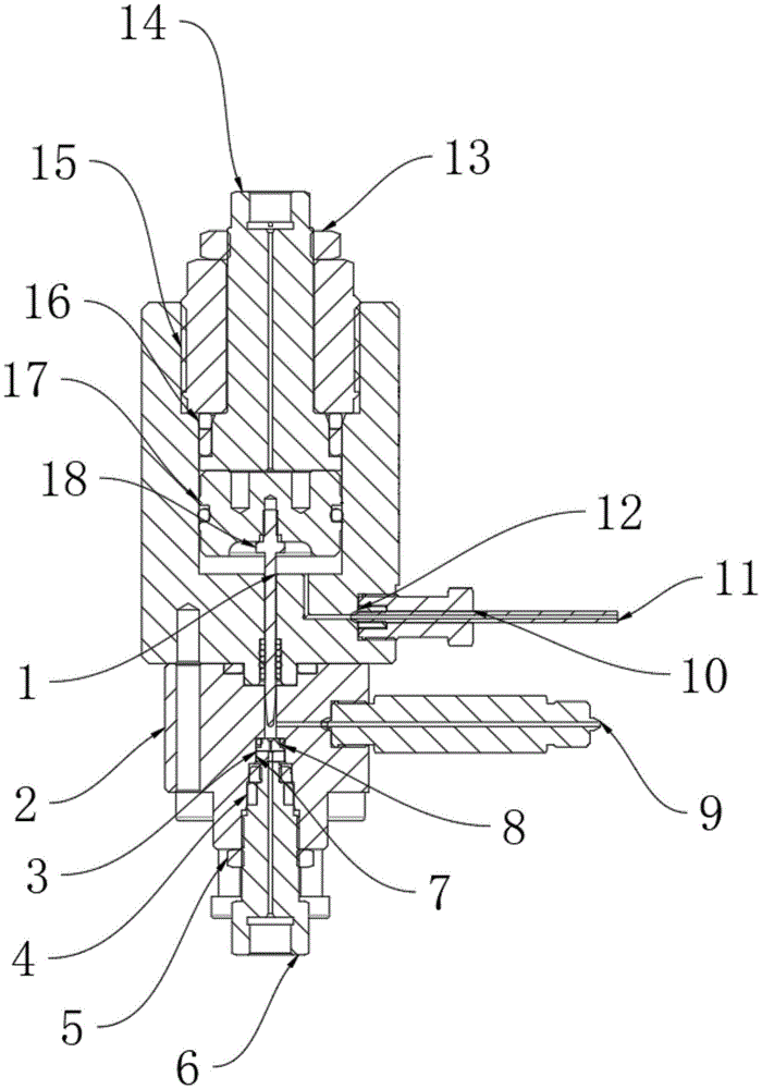
图1为本实用新型的整体结构示意图;Fig. 1 is the overall structure schematic diagram of the present utility model;
图2为本实用新型的下接头连接结构示意图;2 is a schematic diagram of the connection structure of the lower joint of the present invention;
图3为本实用新型的固定杆结构示意图;Figure 3 is a schematic structural diagram of a fixed rod of the present invention;
图4为本实用新型的拉环与固定杆连接部分结构示意图;4 is a schematic structural diagram of the connecting part of the pull ring and the fixing rod of the present invention;
图中:1、阀体;2、下座;3、阀堵;4、直角组合密封件;5、锁紧螺母;6、下接头;7、第一压帽;8、压垫;9、连接头;10、加长压盖;11、管线;12、管线螺母套;13、压紧螺母;14、上接头;15、第二压帽;16、垫片;17、活塞;18、阀针;19、连接孔;20、阀板安装孔;21、固定杆;22、拉环;23、密封垫圈;24、螺纹段;25、顶板;26、转轴。In the figure: 1. valve body; 2. lower seat; 3. valve plug; 4. right-angle combined seal; 5. locking nut; 6. lower joint; 7. first pressure cap; 8. pressure pad; 9. Connector; 10. Extension gland; 11. Pipeline; 12. Pipeline nut sleeve; 13. Compression nut; 14. Upper joint; 15. Second pressure cap; 16. Gasket; 17. Piston; 18. Valve needle ; 19, connecting hole; 20, valve plate mounting hole; 21, fixing rod; 22, pull ring; 23, sealing washer; 24, thread segment; 25, top plate; 26, shaft.
具体实施方式Detailed ways
下面将结合本实用新型实施例中的附图,对本实用新型实施例中的技术方案进行清楚、完整地描述,显然,所描述的实施例仅是本实用新型一部分实施例,而不是全部的实施例。The technical solutions in the embodiments of the present utility model will be clearly and completely described below with reference to the accompanying drawings in the embodiments of the present utility model. Obviously, the described embodiments are only a part of the embodiments of the present utility model, rather than all the implementations. example.
请参阅图1-4,本实用新型提供的一种实施例:超高压回压阀,包括阀体1,阀体1的下端设置有下座2,下座2的内部设置有阀堵3,阀堵3的下方设置有下接头6,下接头6与阀堵3的连接处设置有直角组合密封件4,下接头6的外壁上设置有锁紧螺母5,锁紧螺母5的上方设置有第一压帽7和压垫8,下座2的一侧外壁上设置有连接头9,阀体1的上端设置有上接头14,上接头14的外壁上设置有压紧螺母13,上接头14的下端设置有活塞17,活塞17的内部设置有阀针18,阀体1的一侧外壁上设置有加长压盖10,加长压盖10的内部设置有管线11,管线11的一端通过管线螺母套12与加长压盖10的内部固定连接。1-4, an embodiment provided by the present invention: an ultra-high pressure back pressure valve, comprising a
进一步,下接头6的内部两侧外壁上设置有连接孔19,下接头6的内部设置有阀板安装孔20,且阀板安装孔20与两个连接孔19均位于同一水平线上,连接孔19和阀板安装孔20的内部设置有固定杆21,下接头6的内部两侧外壁上设置的连接孔19起到与阀板安装孔20对应的作用,连接孔19和阀板安装孔20的内部设置的固定杆21起到连接阀板和阀体1的作用。Further, connecting
进一步,固定杆21的两端均设置有螺纹段24,且螺纹段24的外壁上安装有锁紧螺帽,螺纹段24的下端安装有密封垫圈23,且密封垫圈23与连接孔19的外壁紧密贴合,固定杆21的两端均设置的螺纹段24起到便于固定杆21安装锁紧螺帽的作用,螺纹段24的下端安装的密封垫圈23起到密封连接孔19的作用。Further, both ends of the
进一步,固定杆21的一端设置有顶板25,顶板25的一侧设置有拉环22,且拉环22下端的托板通过转轴26与顶板25转动连接,固定杆21的一端设置的顶板25起到连接拉环22的作用,顶板25的一侧设置的拉环22起到便于拉动固定杆21的作用。Further, one end of the
进一步,上接头14与阀体1的连接处设置有第二压帽15和垫片16,且垫片16位于第二压帽15的下方,垫片16与阀体1的内部机械密封连接,上接头14与阀体1的连接处设置的第二压帽15和垫片16起到压紧填充上接头14与阀体1的连接处的作用。Further, the connection between the upper joint 14 and the
进一步,下接头6和上接头14的分别位于阀体1的下端和上端,且下接头6和上接头14的尺寸相等,下接头6和上接头14起到分别为阀体1连接阀杆和阀板的作用。Further, the lower joint 6 and the upper joint 14 are located at the lower end and the upper end of the
工作原理:使用时,通过将阀板上端的阀板安装端插入下接头6的内部,使得安装端内部的阀板安装孔20与下接头6内壁上的两个连接孔19对应,通过将固定杆21插接贯穿阀板安装孔20和连接孔19,从而达到对阀板固定安装的目的,固定完成后,在连接孔19的两侧外壁上安装上两个密封垫圈23用以密封连接孔19,然后在螺纹段24上安装两个锁紧螺帽用以锁紧固定杆21,锁紧后,通过转轴26将顶板25上的拉环22折叠摆放,减小了固定杆21的占地面积,最后再用同样的方式在上接头14上安装上阀杆,此种安装结构更加先进、合理,并且可以大幅提高阀体1的功能实用性。Working principle: When in use, insert the valve plate mounting end at the upper end of the valve plate into the interior of the lower joint 6, so that the valve
对于本领域技术人员而言,显然本实用新型不限于上述示范性实施例的细节,而且在不背离本实用新型的精神或基本特征的情况下,能够以其他的具体形式实现本实用新型。因此,无论从哪一点来看,均应将实施例看作是示范性的,而且是非限制性的,本实用新型的范围由所附权利要求而不是上述说明限定,因此旨在将落在权利要求的等同要件的含义和范围内的所有变化囊括在本实用新型内。不应将权利要求中的任何附图标记视为限制所涉及的权利要求。It will be apparent to those skilled in the art that the present invention is not limited to the details of the above-described exemplary embodiments, and that the present invention may be implemented in other specific forms without departing from the spirit or essential characteristics of the present invention. Therefore, the embodiments are to be considered in all respects as exemplary and not restrictive, and the scope of the present invention is defined by the appended claims rather than the foregoing description, and it is therefore intended that the All changes within the meaning and range of the required equivalents are embraced within the present invention. Any reference signs in the claims shall not be construed as limiting the involved claim.
Claims (6)
Priority Applications (1)
| Application Number | Priority Date | Filing Date | Title |
|---|---|---|---|
| CN202020800941.4U CN212107073U (en) | 2020-05-14 | 2020-05-14 | Ultra high pressure back pressure valve |
Applications Claiming Priority (1)
| Application Number | Priority Date | Filing Date | Title |
|---|---|---|---|
| CN202020800941.4U CN212107073U (en) | 2020-05-14 | 2020-05-14 | Ultra high pressure back pressure valve |
Publications (1)
| Publication Number | Publication Date |
|---|---|
| CN212107073U true CN212107073U (en) | 2020-12-08 |
Family
ID=73622875
Family Applications (1)
| Application Number | Title | Priority Date | Filing Date |
|---|---|---|---|
| CN202020800941.4U Expired - Fee Related CN212107073U (en) | 2020-05-14 | 2020-05-14 | Ultra high pressure back pressure valve |
Country Status (1)
| Country | Link |
|---|---|
| CN (1) | CN212107073U (en) |
Cited By (1)
| Publication number | Priority date | Publication date | Assignee | Title |
|---|---|---|---|---|
| CN119466731A (en) * | 2024-11-11 | 2025-02-18 | 河南理工大学 | Waterless fracturing in-situ low permeability reservoir pressure-displacement-permeation integrated test device and method |
-
2020
- 2020-05-14 CN CN202020800941.4U patent/CN212107073U/en not_active Expired - Fee Related
Cited By (2)
| Publication number | Priority date | Publication date | Assignee | Title |
|---|---|---|---|---|
| CN119466731A (en) * | 2024-11-11 | 2025-02-18 | 河南理工大学 | Waterless fracturing in-situ low permeability reservoir pressure-displacement-permeation integrated test device and method |
| CN119466731B (en) * | 2024-11-11 | 2025-12-30 | 河南理工大学 | Waterless fracturing in-situ low-permeability reservoir integrated pressure-displacement-permeability test device and method |
Similar Documents
| Publication | Publication Date | Title |
|---|---|---|
| CN101806363B (en) | High-pressure high-temperature two-way balance stop valve | |
| CN204314111U (en) | A kind of rock gas sampler fast | |
| CN205479444U (en) | Forge unsteady ball valve of ultra -low temperature upper assembling type of valve body | |
| CN207212307U (en) | A kind of oilfield gas injection production wellhead choke valve | |
| CN204004559U (en) | A kind of sampling T-way valve | |
| CN207364368U (en) | A kind of new safety valve | |
| CN204553961U (en) | A kind of reduction valve | |
| CN218936048U (en) | Petroleum and natural gas transmission monitoring device | |
| CN218625565U (en) | Pressure relief device internally inserted in ground pipeline | |
| CN201462275U (en) | Pipe saddle | |
| CN104455905B (en) | A kind of end cap | |
| CN104453885A (en) | Anti-freezing and anti-theft oil well sampling device without venting | |
| CN210978589U (en) | A pipeline leak detection eccentric hemispherical valve | |
| CN205297465U (en) | Shale gas wellhead assembly | |
| CN201575940U (en) | Novel sampling valve | |
| CN201152382Y (en) | Water medium one way valve | |
| CN201731123U (en) | Transformer leakproof energy-saving air-release valve | |
| CN206874953U (en) | A kind of steam turbine intermediate pressure main stop valve valve rod sealing device | |
| CN2533350Y (en) | Ball heat insulation resistless cock | |
| CN201301973Y (en) | Novel plug valve of gas low-pressure pipeline | |
| CN205745410U (en) | Full welding smithwelding ball valve | |
| CN205504058U (en) | Crossover sub is moulded to copper valve steel | |
| CN204284778U (en) | A kind of end cap | |
| CN205504106U (en) | a pressure limiting valve | |
| CN219345529U (en) | Large-caliber center line butterfly valve with hollow valve plate |
Legal Events
| Date | Code | Title | Description |
|---|---|---|---|
| GR01 | Patent grant | ||
| GR01 | Patent grant | ||
| CF01 | Termination of patent right due to non-payment of annual fee |
Granted publication date: 20201208 |
|
| CF01 | Termination of patent right due to non-payment of annual fee |