CN212101382U - Winding device for processing hot-dip galvanized steel strand of greenhouse - Google Patents
Winding device for processing hot-dip galvanized steel strand of greenhouse Download PDFInfo
- Publication number
- CN212101382U CN212101382U CN202020802836.4U CN202020802836U CN212101382U CN 212101382 U CN212101382 U CN 212101382U CN 202020802836 U CN202020802836 U CN 202020802836U CN 212101382 U CN212101382 U CN 212101382U
- Authority
- CN
- China
- Prior art keywords
- fixedly connected
- winding device
- support frame
- bottom plate
- steel strand
- Prior art date
- Legal status (The legal status is an assumption and is not a legal conclusion. Google has not performed a legal analysis and makes no representation as to the accuracy of the status listed.)
- Expired - Fee Related
Links
- 238000004804 winding Methods 0.000 title claims abstract description 58
- 229910001335 Galvanized steel Inorganic materials 0.000 title claims description 13
- 239000008397 galvanized steel Substances 0.000 title claims description 13
- 229910000831 Steel Inorganic materials 0.000 claims abstract description 4
- 239000010959 steel Substances 0.000 claims abstract description 4
- 238000005246 galvanizing Methods 0.000 claims 1
- 229920000742 Cotton Polymers 0.000 abstract description 4
- 238000000034 method Methods 0.000 description 7
- 239000004020 conductor Substances 0.000 description 6
- 238000005299 abrasion Methods 0.000 description 4
- 206010016256 fatigue Diseases 0.000 description 4
- 230000009286 beneficial effect Effects 0.000 description 1
- 230000007774 longterm Effects 0.000 description 1
- 238000005096 rolling process Methods 0.000 description 1
Images



Landscapes
- Wire Processing (AREA)
Abstract
The utility model discloses a coiling mechanism is used in processing of big-arch shelter hot-galvanize steel strand wires, including support frame and bottom plate, the both sides of bottom plate all are provided with fixed knot and construct, the equal fixedly connected with support frame in both sides on bottom plate top, be provided with winding mechanism between the support frame, one side of support frame is provided with the regulation structure. The utility model discloses a fixed disc has set gradually in fixed knot constructs's inside, remove the wheel, the hinge bar, fixing bolt, draw-in groove and slipmat, the bottom of bottom plate is provided with removes the wheel, the staff pushes away the device behind the position of work, place the hinge bar downwards, the top card of hinge bar is in the inside of draw-in groove, the top of hinge bar adopts fixing bolt to fix, the stability that fixed knot constructs the use has been increased, the bottom of hinge bar is connected with fixed disc, fixed disc is in same level cotton face with removing the wheel, and be provided with the slipmat in fixed disc's inside, avoid sliding, be convenient for mobile device, the availability factor of device has been improved.
Description
Technical Field
The utility model relates to a stranded conductor coiling mechanism technical field specifically is a coiling mechanism is used in processing of big-arch shelter hot-galvanize steel strand wires.
Background
At present, galvanized steel strands need to be coiled and stored after being processed for batch transportation and use, the existing coiling device for galvanized steel strand processing still has some problems, the manual coiling mode is low in efficiency, fatigue is easily generated during long-term operation, and the use efficiency of the device is greatly reduced.
In the process of implementing the present invention, the inventor finds that at least the following problems exist in the prior art and are not solved:
(1) the traditional winding device can not freely change the direction and is inconvenient to fix when the device stops;
(2) the traditional winding device generally adopts a manual winding mode, so that the winding efficiency is greatly reduced;
(3) the traditional winding device cannot easily adjust the placing height of the winding wire, so that the abrasion is serious in the winding process.
SUMMERY OF THE UTILITY MODEL
An object of the utility model is to provide a big-arch shelter hot-galvanize winding device for steel strand wires processing to propose in solving above-mentioned background art can not freely change direction, artifical spiral inefficiency and the more serious problem of wearing and tearing at the rolling in-process.
In order to achieve the above object, the utility model provides a following technical scheme: the winding device for processing the hot-dip galvanized steel strand of the greenhouse comprises support frames and a bottom plate, wherein fixing structures are arranged on two sides of the bottom plate, the support frames are fixedly connected to two sides of the top end of the bottom plate, a winding mechanism is arranged between the support frames, and an adjusting structure is arranged on one side of each support frame.
Preferably, fixed disc, removal wheel, hinge bar, fixing bolt, draw-in groove and slipmat have set gradually in fixed knot constructs's inside, draw-in groove fixed connection is in the both sides of bottom plate, the inside of draw-in groove is provided with the hinge bar, one side on hinge bar top is provided with fixing bolt, the equal fixedly connected with fixed disc in bottom of hinge bar, the inside bottom fixedly connected with slipmat of fixed disc, the both sides at the bottom of the equal fixed connection of removal wheel.
Preferably, the width of the inside of the clamping groove is larger than the width of the outside of the hinge rod, and the fixed disc and the moving wheel are in the same horizontal line.
Preferably, winding mechanism's inside has set gradually and has connected disc, driving motor, wind-up roll, connection pivot and fixing base, it runs through in the top of support frame to connect the pivot, connect the outside fixedly connected with wind-up roll of pivot, the equal fixedly connected with in both sides of wind-up roll connects the disc, driving motor fixed connection is in one side on support frame top, connect one side fixedly connected with fixing base of pivot.
Preferably, the bottom end of the driving motor is communicated with the inside of the connecting rotating shaft, and the inner diameter of the winding roller is equal to the outer diameter of the connecting rotating shaft.
Preferably, the inside of adjusting the structure and having set gradually the inside of connecting plate has set gradually connecting plate, spout, removal seat, gyro wheel, loop bar and sleeve, the connecting plate sets up the one side at the support frame, the equal fixedly connected with loop bar in both sides of connecting plate bottom, the equal swing joint in bottom of loop bar has the sleeve, the bottom fixedly connected with spout of connecting plate, the inside of spout is provided with the removal seat, the equal fixedly connected with gyro wheel in inside of removing the seat.
Preferably, a telescopic structure is formed between the loop bar and the sleeve, and the sleeve is symmetrically distributed around the vertical center line of the connecting plate.
Compared with the prior art, the beneficial effects of the utility model are that: the winding device for processing the hot-dip galvanized steel strand of the greenhouse not only realizes a fixed structure and can freely change directions, but also can fix the device, realizes a winding mechanism, improves the use efficiency of the device by utilizing a mechanical structure, realizes an adjusting structure and reduces the abrasion to the strand;
(1) the fixed disc, the moving wheel, the hinge rod, the fixed bolt, the clamping groove and the anti-slip pad are sequentially arranged in the fixed structure, the moving wheel is arranged at the bottom end of the bottom plate, after the device is pushed to a working position by a worker, the hinge rod is placed downwards, the top end of the hinge rod is clamped in the clamping groove, the top end of the hinge rod is fixed by the fixed bolt, the use stability of the fixed structure is improved, the fixed disc is connected to the bottom end of the hinge rod, the fixed disc and the moving wheel are located on the same horizontal cotton surface, the anti-slip pad is arranged in the fixed disc, sliding is avoided, the device is convenient to move, and the use efficiency of the device is improved;
(2) the connecting disc, the driving motor, the winding roller, the connecting rotating shaft and the fixing seat are sequentially arranged in the winding mechanism, the stranded wire passes through the bottom end of the adjusting structure and then is wound outside the winding roller, the driving motor is started, the driving motor drives the connecting rotating shaft to rotate, the winding roller is connected outside the connecting rotating shaft, and the stranded wire is wound along with the rotation of the winding roller, so that the efficiency of winding the stranded wire is higher than that of manual winding, a large number of stranded wires can be wound, fatigue is avoided, and the efficiency of the device is improved;
(3) the connecting plate has been set gradually through the inside that has set gradually the connecting plate in the inside of adjusting the structure, the spout, remove the seat, the gyro wheel, loop bar and sleeve, the stranded conductor passes between the gyro wheel, do a strong point by the gyro wheel, be convenient for carry out the coiling to the stranded conductor, at the in-process of coiling, it moves at the inside of spout along with the position that the stranded conductor moved to remove the seat, the suitability has been increased, can be according to the height of the high adjustment connecting plate of coiling, shorten the distance between stranded conductor and the wind-up roll, the frictional force that produces when having reduced the removal, the wearing and tearing of stranded conductor have been alleviateed.
Drawings
Fig. 1 is a schematic front view of a cross-sectional structure of the present invention;
FIG. 2 is a side view of the present invention;
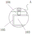
fig. 3 is an enlarged partial sectional view of the utility model at a in fig. 1;
fig. 4 is an enlarged schematic view of the front view of the local section of the fixing disc of the present invention.
In the figure: 1. a fixed structure; 101. fixing the disc; 102. a moving wheel; 103. a hinged lever; 104. fixing the bolt; 105. a card slot; 106. a non-slip mat; 2. a support frame; 3. a winding mechanism; 301. connecting the disks; 302. a drive motor; 303. a wind-up roll; 304. connecting the rotating shaft; 305. a fixed seat; 4. an adjustment structure; 401. a connecting plate; 402. a chute; 403. a movable seat; 404. a roller; 405. a loop bar; 406. a sleeve; 5. a base plate.
Detailed Description
The technical solutions in the embodiments of the present invention will be described clearly and completely with reference to the accompanying drawings in the embodiments of the present invention, and it is obvious that the described embodiments are only some embodiments of the present invention, not all embodiments. Based on the embodiments in the present invention, all other embodiments obtained by a person skilled in the art without creative work belong to the protection scope of the present invention.
Referring to fig. 1-4, the present invention provides an embodiment: a winding device for processing hot-dip galvanized steel strands in a greenhouse comprises support frames 2 and a bottom plate 5, wherein fixing structures 1 are arranged on two sides of the bottom plate 5, the support frames 2 are fixedly connected to two sides of the top end of the bottom plate 5, a winding mechanism 3 is arranged between the support frames 2, and an adjusting structure 4 is arranged on one side of each support frame 2;
the fixed structure 1 is internally provided with a fixed disc 101, a moving wheel 102, a hinged rod 103, a fixed bolt 104, a clamping groove 105 and a non-slip mat 106 in sequence, the clamping groove 105 is fixedly connected to two sides of the bottom plate 5, the hinged rod 103 is arranged in the clamping groove 105, the fixed bolt 104 is arranged on one side of the top end of the hinged rod 103, the bottom ends of the hinged rods 103 are fixedly connected with the fixed disc 101, the bottom end of the fixed disc 101 is fixedly connected with the non-slip mat 106, and the moving wheel 102 is fixedly connected to two sides of the bottom end of the bottom plate 5;
the width of the inside of the clamping groove 105 is larger than that of the outside of the hinge rod 103, and the fixed disc 101 and the moving wheel 102 are in the same horizontal line;
specifically, as shown in fig. 1, 3 and 4, when the mechanism is used, firstly, the bottom end of the bottom plate 5 is provided with the moving wheel 102, after the worker pushes the device to a working position, the hinged rod 103 is placed downwards, the top end of the hinged rod 103 is clamped inside the clamping groove 105, the top end of the hinged rod 103 is fixed by the fixing bolt 104, so that the use stability of the fixing structure 1 is improved, the bottom end of the hinged rod 103 is connected with the fixing disc 101, the fixing disc 101 and the moving wheel 102 are located on the same horizontal cotton surface, and the fixing disc 101 is internally provided with the anti-slip pad 106, so that the sliding is avoided, the device is convenient to move, and the use efficiency of the device is improved;
the winding mechanism 3 is internally provided with a connecting disc 301, a driving motor 302, a winding roller 303, a connecting rotating shaft 304 and a fixed seat 305 in sequence, the connecting rotating shaft 304 penetrates through the top end of the support frame 2, the outside of the connecting rotating shaft 304 is fixedly connected with the winding roller 303, both sides of the winding roller 303 are fixedly connected with the connecting disc 301, the driving motor 302 is fixedly connected to one side of the top end of the support frame 2, the type of the driving motor 302 can be ACM, and one side of the connecting rotating shaft 304 is fixedly connected with the fixed seat 305;
the bottom end of the driving motor 302 is communicated with the inside of the connecting rotating shaft 304, and the inner diameter of the winding roller 303 is equal to the outer diameter of the connecting rotating shaft 304;
specifically, as shown in fig. 1 and fig. 2, when the mechanism is used, firstly, the stranded wire passes through the bottom end of the adjusting structure 4 and then is wound outside the winding roller 303, the driving motor 302 is started, the driving motor 302 drives the connecting rotating shaft 304 to rotate, the winding roller 303 is connected outside the connecting rotating shaft 304, and the stranded wire is wound along with the rotation of the winding roller 303, so that the efficiency of the stranded wire winding mechanism is higher than that of manual winding, a large amount of stranded wires can be wound, fatigue is avoided, and the efficiency of the device is improved;
the adjusting structure 4 is internally provided with a connecting plate 401, a sliding groove 402, a moving seat 403, a roller 404, a loop bar 405 and a sleeve 406 in sequence, the connecting plate 401 is arranged on one side of the support frame 2, the loop bar 405 is fixedly connected to two sides of the bottom end of the connecting plate 401, a telescopic structure is formed between the loop bar 405 and the sleeve 406, the sleeve 406 is symmetrically distributed about the vertical center line of the connecting plate 401, the sleeve 406 is movably connected to the bottom end of the loop bar 405, the sliding groove 402 is fixedly connected to the bottom end of the connecting plate 401, the moving seat 403 is arranged in the sliding groove 402, and the roller 404 is fixedly connected to the moving seat 403;
specifically, as shown in fig. 1 and 2, when the mechanism is used, firstly, the stranded wire passes through the rollers 404, the rollers 404 serve as a supporting point, so that the stranded wire can be conveniently wound, in the winding process, the moving seat 403 moves in the sliding groove 402 along with the moving position of the stranded wire, the applicability is increased, the height of the connecting plate 401 can be adjusted according to the winding height, the distance between the stranded wire and the winding roller 303 is shortened, the friction force generated in the moving process is reduced, and the abrasion of the stranded wire is reduced.
The working principle is as follows: the utility model discloses when using, at first, the bottom of bottom plate 5 is provided with removes wheel 102, the staff pushes away the device behind the position of work, place hinge bar 103 downwards, the top card of hinge bar 103 is in the inside of draw-in groove 105, the top of hinge bar 103 adopts fixing bolt 104 to fix, the stability that fixed knot constructs 1 and uses has been increased, the bottom of hinge bar 103 is connected with fixed disc 101, fixed disc 101 is in same level cotton face with removing wheel 102, and be provided with slipmat 106 in the inside of fixed disc 101, avoid sliding, the mobile device of being convenient for, the availability factor of device has been improved.
Afterwards, the stranded wire passes the bottom of adjusting structure 4 and winds the outside of wind-up roll 303 again, starts driving motor 302, and driving motor 302 drives and connects pivot 304 and rotate, and the external connection of connecting pivot 304 has wind-up roll 303, along with the rotation of wind-up roll 303 to carry out the winding processing to the stranded wire, it is efficient than artifical winding, can twine a large amount of stranded wires, and can not tired out, increased the high efficiency of device.
Finally, the stranded wires penetrate through the rollers 404, the rollers 404 serve as supporting points, the stranded wires are convenient to wind, the moving seat 403 moves inside the sliding groove 402 along with the moving position of the stranded wires in the winding process, applicability is improved, the height of the connecting plate 401 can be adjusted according to the height of the wound stranded wires, the distance between the stranded wires and the winding roller 303 is shortened, friction force generated in moving is reduced, and abrasion of the stranded wires is reduced.
It is obvious to a person skilled in the art that the invention is not restricted to details of the above-described exemplary embodiments, but that it can be implemented in other specific forms without departing from the spirit or essential characteristics of the invention. The present embodiments are therefore to be considered in all respects as illustrative and not restrictive, the scope of the invention being indicated by the appended claims rather than by the foregoing description, and all changes which come within the meaning and range of equivalency of the claims are therefore intended to be embraced therein. Any reference sign in a claim should not be construed as limiting the claim concerned.
Claims (7)
1. The utility model provides a big-arch shelter hot dip galvanizing steel strand wires processing is with take-up device, includes support frame (2) and bottom plate (5), its characterized in that: the utility model discloses a take-up mechanism, including bottom plate (5), the both sides of bottom plate (5) all are provided with fixed knot and construct (1), the equal fixedly connected with support frame (2) in both sides on bottom plate (5) top, be provided with winding mechanism (3) between support frame (2), one side of support frame (2) is provided with adjusts structure (4).
2. The winding device for processing the hot-dip galvanized steel strand for the greenhouse of claim 1, wherein the winding device comprises: the inside of fixed knot structure (1) has set gradually fixed disc (101), has removed wheel (102), hinge bar (103), fixing bolt (104), draw-in groove (105) and slipmat (106), draw-in groove (105) fixed connection is in the both sides of bottom plate (5), the inside of draw-in groove (105) is provided with hinge bar (103), one side on hinge bar (103) top is provided with fixing bolt (104), the equal fixedly connected with fixed disc (101) in bottom of hinge bar (103), the inside bottom fixedly connected with slipmat (106) of fixed disc (101), the both sides of the equal fixed connection in bottom plate (5) of removal wheel (102).
3. The winding device for processing the hot-dip galvanized steel strand for the greenhouse of claim 2, characterized in that: the width of the inner part of the clamping groove (105) is larger than that of the outer part of the hinge rod (103), and the fixed disc (101) and the moving wheel (102) are positioned on the same horizontal line.
4. The winding device for processing the hot-dip galvanized steel strand for the greenhouse of claim 1, wherein the winding device comprises: the inside of winding mechanism (3) has set gradually connection disc (301), driving motor (302), wind-up roll (303), connection pivot (304) and fixing base (305), connect pivot (304) and run through in the top of support frame (2), the outside fixedly connected with wind-up roll (303) of connection pivot (304), the equal fixedly connected with in both sides of wind-up roll (303) connects disc (301), driving motor (302) fixed connection is in one side on support frame (2) top, connect one side fixedly connected with fixing base (305) of pivot (304).
5. The winding device for processing the hot-dip galvanized steel strand for the greenhouse of claim 4, wherein the winding device comprises: the bottom end of the driving motor (302) is communicated with the inside of the connecting rotating shaft (304), and the inner diameter of the winding roller (303) is equal to the outer diameter of the connecting rotating shaft (304).
6. The winding device for processing the hot-dip galvanized steel strand for the greenhouse of claim 1, wherein the winding device comprises: adjust the inside of structure (4) and set gradually the inside of connecting plate (401) and set gradually connecting plate (401), spout (402), remove seat (403), gyro wheel (404), loop bar (405) and sleeve (406), connecting plate (401) set up the one side at support frame (2), the equal fixedly connected with loop bar (405) in both sides of connecting plate (401) bottom, the equal swing joint in bottom of loop bar (405) has sleeve (406), the bottom fixedly connected with spout (402) of connecting plate (401), the inside of spout (402) is provided with removes seat (403), the equal fixedly connected with gyro wheel (404) in inside of removing seat (403).
7. The winding device for processing the hot-dip galvanized steel strand for the greenhouse of claim 6, wherein the winding device comprises: a telescopic structure is formed between the loop bar (405) and the sleeve (406), and the sleeve (406) is symmetrically distributed around the vertical center line of the connecting plate (401).
Priority Applications (1)
| Application Number | Priority Date | Filing Date | Title |
|---|---|---|---|
| CN202020802836.4U CN212101382U (en) | 2020-05-14 | 2020-05-14 | Winding device for processing hot-dip galvanized steel strand of greenhouse |
Applications Claiming Priority (1)
| Application Number | Priority Date | Filing Date | Title |
|---|---|---|---|
| CN202020802836.4U CN212101382U (en) | 2020-05-14 | 2020-05-14 | Winding device for processing hot-dip galvanized steel strand of greenhouse |
Publications (1)
| Publication Number | Publication Date |
|---|---|
| CN212101382U true CN212101382U (en) | 2020-12-08 |
Family
ID=73622349
Family Applications (1)
| Application Number | Title | Priority Date | Filing Date |
|---|---|---|---|
| CN202020802836.4U Expired - Fee Related CN212101382U (en) | 2020-05-14 | 2020-05-14 | Winding device for processing hot-dip galvanized steel strand of greenhouse |
Country Status (1)
| Country | Link |
|---|---|
| CN (1) | CN212101382U (en) |
Cited By (1)
| Publication number | Priority date | Publication date | Assignee | Title |
|---|---|---|---|---|
| CN112693975A (en) * | 2020-12-21 | 2021-04-23 | 顾少文 | Power grid is erect and is used towing line ware |
-
2020
- 2020-05-14 CN CN202020802836.4U patent/CN212101382U/en not_active Expired - Fee Related
Cited By (1)
| Publication number | Priority date | Publication date | Assignee | Title |
|---|---|---|---|---|
| CN112693975A (en) * | 2020-12-21 | 2021-04-23 | 顾少文 | Power grid is erect and is used towing line ware |
Similar Documents
| Publication | Publication Date | Title |
|---|---|---|
| CN110775720B (en) | Cable rack for bypass operation of power distribution network | |
| CN209222917U (en) | A kind of copper wire pay-off guide device for cable production | |
| CN111200256B (en) | Cable laying equipment for power engineering and implementation method thereof | |
| CN114542903A (en) | Building monitoring device based on BIM | |
| CN105060007B (en) | A kind of electric wire stretches wrap-up | |
| CN115402837B (en) | Coiling mechanism of stainless steel band | |
| CN209815381U (en) | Two-in-one conductor rewinder with wire storage protection function | |
| CN218619546U (en) | Building engineering cable pay-off | |
| CN210418807U (en) | Winding drum device for hoisting equipment | |
| CN212880718U (en) | Portable manual hose winding machine | |
| CN214934470U (en) | Waterproofing membrane's coiling mechanism | |
| CN220412436U (en) | Adjustable winder for wires and cables | |
| CN212769189U (en) | An electromechanical engineering cable retracting device | |
| CN210594734U (en) | Copper line unwinding device | |
| CN211496344U (en) | Unwinding device for elastic wire processing | |
| CN216889441U (en) | Special cable receives line and uses stabilising arrangement | |
| CN110884935B (en) | Fixed-width unwinding device for braid processing | |
| CN213170845U (en) | Steel wire rope winding device | |
| CN113896059A (en) | Wire take-up and pay-off device capable of avoiding construction influenced by chaos of wire and cable take-up and pay-off process | |
| CN210064799U (en) | Cable coiling machine | |
| CN219602955U (en) | Cable winding device | |
| CN220664326U (en) | Material collecting device for anode titanium mesh calendaring | |
| CN210339899U (en) | Cable laying equipment of acting as go-between | |
| CN218210438U (en) | Drying device is used in fishing net processing | |
| CN224232404U (en) | Wire and cable stranding machine |
Legal Events
| Date | Code | Title | Description |
|---|---|---|---|
| GR01 | Patent grant | ||
| GR01 | Patent grant | ||
| CF01 | Termination of patent right due to non-payment of annual fee | ||
| CF01 | Termination of patent right due to non-payment of annual fee |
Granted publication date: 20201208 |