CN212079121U - Airtight isobaric passive drainage piece with built-in outer frame and mullion - Google Patents
Airtight isobaric passive drainage piece with built-in outer frame and mullion Download PDFInfo
- Publication number
- CN212079121U CN212079121U CN202020478805.8U CN202020478805U CN212079121U CN 212079121 U CN212079121 U CN 212079121U CN 202020478805 U CN202020478805 U CN 202020478805U CN 212079121 U CN212079121 U CN 212079121U
- Authority
- CN
- China
- Prior art keywords
- cavity
- drainage
- diversion
- isobaric
- water
- Prior art date
- Legal status (The legal status is an assumption and is not a legal conclusion. Google has not performed a legal analysis and makes no representation as to the accuracy of the status listed.)
- Active
Links
- 238000007789 sealing Methods 0.000 claims abstract description 76
- XLYOFNOQVPJJNP-UHFFFAOYSA-N water Substances O XLYOFNOQVPJJNP-UHFFFAOYSA-N 0.000 claims abstract description 53
- 239000004576 sand Substances 0.000 claims abstract description 22
- 230000002265 prevention Effects 0.000 claims abstract description 14
- 238000009825 accumulation Methods 0.000 claims description 13
- 241000255925 Diptera Species 0.000 abstract description 7
- 230000000694 effects Effects 0.000 abstract description 7
- 230000005484 gravity Effects 0.000 abstract description 5
- 238000004519 manufacturing process Methods 0.000 abstract description 2
- 238000009413 insulation Methods 0.000 description 18
- 239000011521 glass Substances 0.000 description 16
- 239000000463 material Substances 0.000 description 9
- 230000000903 blocking effect Effects 0.000 description 3
- 239000000565 sealant Substances 0.000 description 2
- 238000000926 separation method Methods 0.000 description 2
- 230000032683 aging Effects 0.000 description 1
- 230000000712 assembly Effects 0.000 description 1
- 238000000429 assembly Methods 0.000 description 1
- 230000009286 beneficial effect Effects 0.000 description 1
- 238000005286 illumination Methods 0.000 description 1
- 238000009434 installation Methods 0.000 description 1
- 230000004048 modification Effects 0.000 description 1
- 238000012986 modification Methods 0.000 description 1
- 230000000149 penetrating effect Effects 0.000 description 1
- 239000000126 substance Substances 0.000 description 1
- 238000009423 ventilation Methods 0.000 description 1
Images




Landscapes
- Specific Sealing Or Ventilating Devices For Doors And Windows (AREA)
Abstract
The utility model relates to the technical field of doors and windows, in particular to an airtight isobaric passive drainage component with a built-in outer frame and a built-in mullion, which comprises a drainage component, wherein the drainage component is divided into an upper diversion cavity and a lower closed cavity through a diversion step platform, a clamping groove is arranged outside the diversion cavity, a water and sand prevention unit is arranged in the clamping groove, a swing sealing sheet in the water and sand prevention unit is matched with the diversion step platform to form a ponding cavity, a drainage hole is vertically arranged at the top of the drainage component and communicated with the ponding cavity, the drainage component has a simple structure and low manufacturing cost, the water and sand prevention unit in the drainage component can prevent external wind sand or mosquitoes from entering the isobaric cavity through the diversion cavity to enter the room, after some rainwater is accumulated in the ponding cavity in the drainage component, the swing sealing component can be pressed downwards under the gravity action of the rainwater, so as to open the ponding cavity, the rainwater in the ponding cavity can flow out through the diversion cavity under the action, the drainage effect is obvious.
Description
The technical field is as follows:
the utility model relates to a door and window technical field, concretely relates to frame and built-in airtight isobaric passive form drainage member of well club.
Background art:
the window is one of the important components of a building, ventilation and illumination of a room in life need to be realized through the window, but when the window is used for a long time, a sealing rubber strip on the side edge of glass of the window is aged, the sealing effect is greatly reduced, rainwater can flow into a window frame along the aged sealing rubber strip to form accumulated water in rainy days, the accumulated water is not easy to drain, a sectional material is soaked in the accumulated water for a long time, the service life of the window can be shortened, harmful substances can be bred, the existing window is mainly provided with a drain hole which is mainly formed in a frame body of a door or a window, so that the accumulated water in the frame body of the door or the window or a rail groove is drained, although the drain hole is formed in the frame body of the door or the window, the water can be drained conveniently, the accumulated water of the door or the window is avoided, but under the condition of severe weather, such as rain, the amount of rain is, the drain hole can not timely discharge a large amount of rainwater, thereby leading to rainwater to store up in door and window frame or door and window rail groove once more, ponding takes place to flow backward very easily under the drive of outside air current moreover, thereby cause indoor intaking or wall body to soak, not only can cause the influence to the room inside, and after room wall body soaks, it also can cause the influence to the life-span of wall body, and because of the drain hole is with external atmosphere intercommunication, its mosquito just can probably enter into indoorly through the drain hole, cause the influence to the personnel of living in.
How to design a drainage function that can improve the window, prevent that the rainwater from flowing backward into indoorly, also can prevent that mosquito or sand blown by the wind from entering into indoor drainage spare is the problem that needs to solve promptly now.
The invention content is as follows:
aiming at the problems that the existing door and window drain holes can not drain rainwater in time in severe weather, so that rainwater can flow backward into a room, or mosquito sand blown into the room through the drain holes, the utility model provides an airtight isobaric passive drainage piece arranged in a frame and a mullion, which can drain the rainwater passively through the self gravity of accumulated water under the action of an isobaric cavity and can drain the accumulated rainwater well in severe weather; through the water-flowing sand prevention unit that sets up in the drainage component, can effectually block sand blown by the wind or the mosquito and enter into indoorly under door and window locking state, make it can not get into in the isobaric cavity through the wash port of drainage component.
The utility model provides a scheme that its technical problem adopted is: an airtight isobaric passive drainage piece is arranged in an outer frame and a mullion and comprises a drainage piece, a diversion step platform, a water and sand prevention unit and a clamping groove, wherein the drainage piece is divided into an upper cavity and a lower cavity through the diversion step platform, the upper cavity is a diversion cavity, and the lower cavity is a closed cavity; the diversion step platform comprises a high diversion inclined plane, a low diversion inclined plane and a diversion vertical plane, the high diversion inclined plane and the low diversion inclined plane are in a step shape from high to low through the diversion vertical plane, the clamping groove is formed in the outer side of the diversion cavity, the notch of the clamping groove faces inwards, the water and sand prevention unit is arranged in the clamping groove and comprises a clamping head and a swinging sealing piece, the clamping head and the swinging sealing piece are integrated, the clamping head is clamped in the clamping groove in a matching mode, the swinging sealing piece is inclined below the outer side portion of the clamping groove, and the swinging sealing piece is matched with the diversion vertical plane to form a water accumulation cavity; and a water drainage hole is vertically formed downwards at the top of the water drainage piece and communicated with the water accumulation chamber.
An airtight isobaric passive drainage piece with an outer frame and a mullion is arranged in the outer frame and the mullion and comprises a window frame, a window sash, a drainage piece, a flow guide step platform, a water and sand prevention unit and a clamping groove, wherein the drainage piece is divided into an upper cavity and a lower cavity through the flow guide step platform, the upper cavity is a flow guide cavity, and the lower cavity is a closed cavity; the diversion step platform comprises a high diversion inclined plane, a low diversion inclined plane and a diversion vertical plane, the high diversion inclined plane and the low diversion inclined plane are in a step shape from high to low through the diversion vertical plane, the clamping groove is formed in the outer side of the diversion cavity, the notch of the clamping groove faces inwards, the water and sand prevention unit is arranged in the clamping groove and comprises a clamping head and a swinging sealing piece, the clamping head and the swinging sealing piece are integrated, the clamping head is matched and clamped in the clamping groove, the swinging sealing piece is inclined below the part, located on the outer side of the clamping groove, of the clamping head, and the swinging sealing piece is matched with the diversion vertical plane to form a water accumulation cavity; a water drainage hole is vertically formed downwards at the top of the water drainage piece and communicated with the water accumulation chamber; the window sash comprises a transverse outer side profile, a transverse inner side profile, a vertical outer side profile and a vertical inner side profile, and the window frame comprises a window frame transverse inner side profile, a window frame transverse outer side profile, a window frame vertical inner side profile and a window frame vertical outer side profile; glass is arranged between the transverse outer side sectional material and the transverse inner side sectional material and between the vertical outer side sectional material and the vertical inner side sectional material; the outer side and the inner side of the glass between the transverse outer side profile and the transverse inner side profile are fixed with the transverse outer side profile and the transverse inner side profile through sealing rubber strips, sealing strips are arranged below the glass, a pad bridge is arranged below the sealing strips, a heat insulation block is arranged between the transverse outer side profile and the transverse inner side profile below the pad bridge, the heat insulation block is fixed between the transverse outer side profile and the transverse inner side profile below the pad bridge through upper and lower supporting components, and through holes vertically penetrate through the top and the bottom of a cavity in the transverse outer side profile; a heat insulation block is arranged between the window frame transverse inner side profile and the window frame transverse outer side profile, the heat insulation block is fixed between the window frame transverse inner side profile and the window frame transverse outer side profile through upper and lower supporting components, a sealing element is installed above the supporting components in a matching manner, and the transverse outer side profile and the window frame transverse outer side profile form a window sash bottom transverse isobaric cavity through the sealing element; the drainage piece is arranged in an inner cavity of the window frame transverse outer side section in a matching manner, the top of the inner cavity of the window frame transverse outer side section is provided with a through hole communicated to the transverse isobaric cavity, the through hole vertically corresponds to a drainage hole at the top of the drainage piece, and the left side of the inner cavity of the window frame transverse outer side section is provided with a water flowing hole corresponding to the diversion cavity; the outer side and the inner side of the glass between the vertical outer side profile and the vertical inner side profile are fixed with the vertical outer side profile and the vertical inner side profile through sealing rubber strips, sealing strips are arranged below the glass, a pad bridge is arranged below the sealing strips, a heat insulation block is arranged between the vertical outer side profile and the vertical inner side profile below the pad bridge, and the heat insulation block is fixed between the vertical outer side profile and the vertical inner side profile through upper and lower supporting assemblies; an air inlet hole and an air outlet hole are formed in the cavity of the vertical outer side section bar, the height of the air inlet hole is higher than that of the air outlet hole, the air inlet hole and the air outlet hole have a height difference, and the air inlet hole is connected with the atmosphere; the window frame is characterized in that a heat insulation block is arranged between a vertical inner side profile of the window frame and a vertical outer side profile of the window frame, the heat insulation block is fixed between the vertical inner side profile of the window frame and the vertical outer side profile of the window frame through upper and lower supporting components, a sealing element is installed above the supporting components in a matched mode, the vertical outer side profile and the vertical outer side profile of the window frame form a vertical isobaric cavity of the side portion of the window sash through the sealing element, an air outlet is communicated with the vertical isobaric cavity of the side portion of the window sash, and the horizontal isobaric.
Furthermore, still include well club, well club is fixed to be established in the casement top, is equipped with two drainage member in well club, and opens the discharge orifice that has corresponding with drainage member water conservancy diversion chamber in the outdoor side of well club.
Furthermore, the matched sleeves are arranged on two drainage pieces in the transverse outer side section bar of the window frame.
Further, the swing seal piece has elasticity.
Furthermore, a groove is formed at the corner of the swing sealing piece and the chuck.
Furthermore, sealing separation blades are hermetically arranged at two ends of the drainage piece.
Furthermore, the top of the drainage piece is vertically provided with two drainage holes downwards, and the two drainage holes are horizontally symmetrical.
The utility model has the advantages that: the utility model discloses there are five beneficial effects.
First, drainage component simple structure, low in manufacturing cost, the drainage effect is showing moreover, through the sealed separation blade of both sides seal installation, can prevent the condition that the rainwater leaked from drainage component's both ends head.
And secondly, the drainage part is divided into an upper cavity and a lower cavity through a diversion step platform, the upper cavity is a diversion cavity, the lower cavity is a closed cavity, and the closed cavity can also enhance the sound and heat insulation capability of the window profile.
Third, through matching the water-flowing sand prevention unit of suit in the drainage piece draw-in groove, thereby can prevent that external sand blown by the wind or mosquito from entering into the isobaric intracavity through the water conservancy diversion chamber and entering into indoorly, and the swing sealing piece in the water-flowing sand prevention unit is elastic, the recess of seting up at swing sealing piece and dop junction can make the swing sealing piece more nimble, after some rainwater had been accumulated in the ponding intracavity in the drainage piece, under the action of gravity of rainwater, just can push down the swing sealing piece, thereby open the ponding chamber, the rainwater in the ponding intracavity just can flow through the water conservancy diversion chamber under the effect of water conservancy diversion stair platform.
Fourthly, the bottom transverse isobaric cavity formed by the closed state of the window frame and the window sash is communicated with the two side vertical isobaric cavities, the bottom transverse isobaric cavity can be connected with the outside atmosphere through the air inlet holes formed in the two side vertical isobaric cavities to form isobaric pressure, and rainwater cannot be discharged due to the fact that the air pressure in the cavity of the window frame and the window sash is not equal to the outdoor air pressure or is smaller than the outdoor air pressure when the window frame and the window sash are in the closed state under the isobaric condition.
Fifthly, after rainwater enters the window sash through the aged sealing rubber strips, the rainwater can vertically penetrate through the top and the bottom of the inner cavity of the transverse outer profile to flow into the isobaric cavity, and under the isobaric action of the isobaric cavity, the rainwater flows downwards into the drainage piece through the through hole formed in the top of the inner cavity of the transverse outer profile of the window frame, is directly drained by the drainage piece, and cannot be accumulated or poured into a room or be immersed into a wall.
Description of the drawings:
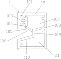
fig. 1 is a schematic structural view of a drainage member.
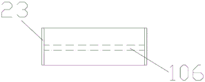
Fig. 2 is a plan view of the drain member.
Fig. 3 is a front view of the drain member.
Fig. 4 is an exterior view of the door and window.
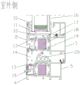
Fig. 5 is a sectional view B-B' of fig. 4.
Fig. 6 is a schematic view of the structure of the portion C in fig. 5.
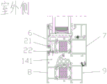
Fig. 7 is a sectional view a-a' of fig. 4.
Fig. 8 is a schematic view of the structure of the portion D in fig. 7.
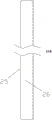
Fig. 9 is a side view of the door and window.
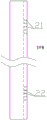
Fig. 10 is a right side view of the sash.
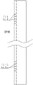
Fig. 11 is a left side view of the sash.
In the figure: 1-drainage piece, 101-clamping groove, 102-drainage hole, 103-clamping head, 104-arc groove, 105-swing sealing piece, 106-diversion cavity, 107-accumulated water cavity, 108-high diversion inclined plane, 109-diversion vertical plane, 110-low diversion inclined plane, 111-closed cavity, 2-transverse outside section bar, 3-transverse inside section bar, 4-window frame transverse outside section bar, 5-window frame transverse inside section bar, 6-vertical outside section bar, 7-vertical inside section bar, 8-window frame vertical outside section bar, 9-window frame vertical inside section bar, 10-sealing rubber strip, 11-sealing strip, 12-bridge, 13-through hole, 14-window sash bottom transverse isobaric cavity body, 141-window sash side vertical isobaric cavity body, 15-water flowing hole, 16-glass, 17-upper supporting piece, 18-heat insulation block, 19-lower supporting piece, 20-sealing piece, 21-air inlet hole, 22-air outlet hole, 23-sealing baffle sheet, 24-mullion, 25-window frame and 26-window sash.
The specific implementation mode is as follows:
the present invention will be further explained with reference to the drawings and examples.
In view of the above problems, the present embodiment provides an airtight and isobaric passive drainage device with an outer frame and a mullion, as shown in fig. 1, the drainage member 1 is comprised, the drainage member 1 is sealed into an upper chamber and a lower chamber through a diversion step platform, the upper chamber is a diversion cavity 106, the lower chamber is a closed cavity 111, the diversion step platform comprises a high diversion inclined plane 108, a low diversion inclined plane 110 and a diversion vertical plane 109, the high diversion inclined plane 108 and the low diversion inclined plane 110 are in a step shape from high to low through the diversion vertical plane 109, a clamping groove 101 is arranged on the outer side of the diversion cavity, a notch of the clamping groove 101 faces inwards, a water and sand prevention unit is sleeved in the clamping groove 101 in a matching manner, the water and sand prevention unit comprises a clamping head 103 and a swinging sealing sheet 105, the clamping head 103 and the swinging sealing sheet 105 are integrated, the clamping head 103 is clamped in the clamping groove 101 in a matching mode, the swinging sealing sheet 105 inclines below the outer side portion of the clamping head 103, and the head end of the swinging sealing sheet 105 is matched with the flow guide vertical face 109 to form a water collecting cavity 107; sealing blocking sheets 23 are fixed at two ends of the drainage member 1 in a sealing manner, an arc-shaped groove 104 is formed at the corner of the swing sealing sheet 105 and the clamping head 103, a drainage hole 102 is vertically formed downwards at the top of the drainage member 1, the drainage hole 102 is communicated with a water accumulation cavity 107, and as shown in fig. 2, two drainage holes 102 are formed and are arranged in a mirror image manner.
When the drainage piece is applied to the field of doors and windows, the drainage piece 1 is arranged in a frame body of the doors and windows, a through hole is formed in the drainage piece 1 at a position corresponding to the diversion cavity 106 on the frame body, the through hole is communicated with the diversion cavity 106, and a through hole is formed in the frame body corresponding to the upper part of the drainage hole 102; under the condition of small rainfall, after rainwater flows into the frame body of the door and window through the aged sealant, the rainwater can pass through the drain hole 102 through the through hole of the frame body above the drain hole 102 and then is stored in the water accumulation cavity 107, when the rainwater is stored to a certain amount, the swinging sealing piece 105 is pressed downwards under the action of the gravity of the rainwater, so that the water accumulation cavity 107 is opened, the water in the water accumulation cavity 107 can pass through the flow guide cavity 106 under the action of the flow guide stepped platform, and then flows out of the room from the through hole on the frame body at the position corresponding to the flow guide cavity 106 without being stored in the frame body; when the weather is bad and the rainfall is large, after rainwater flows into the frame body of the door and window through the aged sealant strips, the swinging sealing piece 105 is pressed downwards under the action of the gravity of the rainwater, the accumulated water cavity is directly opened, and the rainwater flows out of the room through the flow guide cavity 106 and the through holes in the frame body at the position corresponding to the flow guide cavity 106; and swing sealing piece 105 can prevent that external sand blown by the wind or mosquito from entering into the isobaric intracavity through the water conservancy diversion chamber thereby entering into indoorly, effectually reached prevent wind the mosquito-proof effect of sand blown by the wind.
Example 2, this example provides an airtight and isobaric passive drainage member with an outer frame and a mullion.
In the embodiment, the window comprises a drainage piece, a window frame, a window sash and a mullion, wherein the mullion is arranged above the window sash; the drainage member 1 is sealed into an upper cavity and a lower cavity through a diversion step platform, the upper cavity is a diversion cavity 106, the lower cavity is a sealed cavity 111, the diversion step platform comprises a high diversion inclined plane 108, a low diversion inclined plane 110 and a diversion vertical plane 109, the high diversion inclined plane 108 and the low diversion inclined plane 110 are in a step shape from high to low through the diversion vertical plane 109, a clamping groove 101 is arranged on the outer side of the diversion cavity, a notch of the clamping groove 101 faces inwards, a water and sand passing unit is sleeved in the clamping groove 101 in a matching mode and comprises a clamping head 103 and a swinging sealing sheet 105, the clamping head 103 and the swinging sealing sheet 105 are integrated, the clamping head 103 is clamped in the clamping groove 101 in a matching mode, the swinging sealing sheet 105 inclines below the clamping head 103, the outer side portion of the clamping groove 101, the head end of the swinging sealing sheet 105 is matched with the diversion vertical plane 109 to form; sealing blocking pieces 23 are fixed at two ends of the drainage member 1 in a sealing manner, an arc-shaped groove 104 is formed at the corner of the swing sealing piece 105 and the clamping head 103, a drainage hole 102 is vertically and downwards formed in the top of the drainage member 1, the drainage hole 102 is communicated with a water accumulation cavity 107, and the drainage holes 102 are two and are formed in a mirror image manner; the window sash 26 comprises a transverse outer profile 2, a transverse inner profile 3, a vertical outer profile 6 and a vertical inner profile 7, and the window frame 25 comprises a window frame transverse inner profile 5, a window frame transverse outer profile 4, a window frame vertical inner profile 9 and a window frame vertical outer profile 8.
As shown in fig. 6, a glass 16 is arranged between the transverse outer profile 2 and the transverse inner profile 3, sealing rubber strips 10 are arranged on two sides of the glass 16, the glass 16 is fixed with the transverse outer profile 2 and the transverse inner profile 3 through the sealing rubber strips 10, a sealing strip 11 is fixed below the glass 16, a bridge pad 12 is fixed below the sealing strip 11, a heat insulation block 18 is arranged between the transverse outer profile 2 and the transverse inner profile 3 below the bridge pad 12, the heat insulation block 18 is fixed between the transverse outer profile 2 and the transverse inner profile 3 below the bridge pad 12 through an upper support member 17 and a lower support member 19, and a through hole 13 vertically penetrates through the top and the bottom of a cavity in the transverse outer profile 2.
The window frame transverse outer section bar 4 and the window frame transverse inner section bar 5 are arranged below the transverse outer section bar 2 and the transverse inner section bar 3; a heat insulation block 18 is arranged between the window frame transverse outer side section bar 4 and the window frame transverse inner side section bar 5, the heat insulation block 18 is fixed between the window frame transverse outer side section bar 4 and the window frame transverse inner side section bar 5 through an upper support member 17 and a lower support member 19, and a sealing member 20 is installed above the upper support member 17 in a matching mode.
The transverse outer section bar 2 and the transverse outer section bar 4 of the window frame form a window sash bottom transverse isobaric cavity 14 through a sealing element 20; the number of the drainage pieces 1 is two, the drainage pieces 1 are installed in the inner cavity of the window frame transverse outer side section bar 4 in a matching mode, the top of the window frame transverse outer side section bar 4 is provided with a through hole 13 which is communicated to a transverse isobaric cavity 14, and the top of the window frame transverse outer side section bar 4 is provided with a through hole 13 which vertically corresponds to a drainage hole 102 in the top of the drainage piece 1; the left side of the cavity in the window frame transverse outer section bar 4 is provided with a water flowing hole 15 corresponding to the flow guide cavity 106, and the water flowing hole 15 is communicated with the outside.
As shown in fig. 8, glass 16 between a vertical outer profile 6 and a vertical inner profile 7 is fixed to the vertical outer profile 6 and the vertical inner profile 7 through sealing rubber strips 10 on two sides, a sealing strip 11 is fixed below the glass 16, a bridge pad 12 is fixed below the sealing strip 11, a heat insulation block 18 is arranged between the vertical outer profile 6 and the vertical inner profile 7 below the bridge pad 12, and the heat insulation block 18 is fixed between the vertical outer profile 6 and the vertical inner profile 7 below the bridge pad 12 through an upper support member 17 above and a lower support member 19 below; an air inlet hole 21 and an air outlet hole 22 are formed in the inner cavity of the vertical outer side profile 6, the air inlet hole 21 is higher than the air outlet hole 22, a height difference exists between the air inlet hole 21 and the air outlet hole 22, and the air inlet hole 21 is connected with the atmosphere.
The window frame vertical outer side sectional material 8 and the window frame vertical inner side sectional material 9 are arranged below the vertical outer side sectional material 6 and the vertical inner side sectional material 7; a heat insulation block 18 is arranged between the window frame vertical outer side section bar 8 and the window frame vertical inner side section bar 9, the heat insulation block 18 is fixed between the window frame transverse outer side section bar 4 and the window frame transverse inner side section bar 5 through an upper support member 17 and a lower support member 19, and a sealing member 20 is installed above the upper support member 17 in a matching manner.
The vertical outer side section bar 6 and the window frame vertical outer side section bar are combined through a sealing element 20 to form a window sash side vertical isobaric cavity 14, and the window sash bottom horizontal isobaric cavity is communicated with the window sash side vertical isobaric cavity to form a chimney effect.
As shown in fig. 4 or 5, a mullion 24 is arranged between the window sash and the upper window frame, two drainage members 1 are installed in the mullion 24 in a matching manner, a through hole 13 vertically penetrates through the top of the cavity in the mullion 24, the through hole 13 vertically corresponds to a drainage hole 102 in the top of the drainage member 1, a drain hole 15 corresponding to a drainage member diversion cavity is formed in the left side of the cavity in the mullion 24, and when rainwater enters the frame through an aging sealing rubber strip of glass above the mullion, the rainwater can flow into the drainage member 1 through the through hole 13 and the drainage hole 102 and then flow out of the outdoor through the diversion cavity and the drain hole 15.
When the window sash is used for a period of time, the sealing rubber strips 10 on two sides of the glass 16 can be aged, rainwater can enter the transverse outer side section bar 2 through the sealing rubber strips 10 aged on two sides of the glass 16 in rainy days, then the rainwater enters the transverse equal-pressure cavity 14 at the bottom of the window sash through the through holes 13 vertically penetrating and formed in the top and the bottom of the cavity in the transverse outer side section bar 2, the transverse equal-pressure cavity at the bottom is communicated with the vertical equal-pressure cavities at two sides because the window frame and the window sash are in a closed state, the transverse equal-pressure cavity at the bottom can be connected with the external atmosphere through the air inlet 21 formed in the vertical equal-pressure cavity at the side of the window sash to form equal pressure, under the equal-pressure condition, the rainwater cannot be discharged because the internal air pressure of the window frame and the window sash is not equal to the outdoor air pressure or is smaller than the outdoor air pressure, under the action of the transverse equal, the rainwater flows into the water accumulation cavity 107 through the through hole 13 at the top of the cavity in the section bar 4 on the transverse outer side of the window frame and the water drainage hole 102 at the top of the drainage member 1, the swing sealing sheet 105 is pressed downwards to be opened due to the elasticity of the swing sealing sheet 105, the rainwater in the water accumulation cavity 107 can be drained out of a room through the flow guide cavity 106 and the water flowing hole 15 under the action of the flow guide step platform, the condition that the rainwater is accumulated or flows backwards into the room or is immersed into a wall body is avoided, the drainage effect is remarkable, and the sealing blocking pieces 23 at the two ends of the drainage member 1 can prevent the rainwater from leaking from the two ends of the drainage member.
Example 3, a point of difference from example 2 will be mainly described in relation to the case where the airtight and isobaric passive drainage member is incorporated in the outer frame and the center rail in this example.
In this embodiment, as shown in fig. 10 to 11, the air inlets 21 and the air outlets 22 are multiple and are arranged vertically and symmetrically, and by adding the multiple air inlets 21 and the multiple air outlets 22, a channel of the isobaric cavity 14 contacting with the external atmosphere can be increased, which is better equal to the external air pressure.
The above description is only for the preferred embodiment of the present invention, and the present invention is not limited thereto, and any modification, equivalent replacement and improvement made within the spirit and principle scope of the present invention should be included within the protection scope of the present invention.
Claims (5)
1. An airtight isobaric passive drainage piece is arranged in an outer frame and a mullion, and is characterized by comprising a drainage piece, a diversion step platform, a water and sand prevention unit and a clamping groove, wherein the drainage piece is divided into an upper cavity and a lower cavity through the diversion step platform, the upper cavity is a diversion cavity, and the lower cavity is a closed cavity; the diversion step platform comprises a high diversion inclined plane, a low diversion inclined plane and a diversion vertical plane, the high diversion inclined plane and the low diversion inclined plane are in a step shape from high to low through the diversion vertical plane, the clamping groove is formed in the outer side of the diversion cavity, the notch of the clamping groove faces inwards, the water and sand prevention unit is arranged in the clamping groove and comprises a clamping head and a swinging sealing piece, the clamping head and the swinging sealing piece are integrated, the clamping head is clamped in the clamping groove in a matching mode, the swinging sealing piece is inclined below the outer side portion of the clamping groove, and the swinging sealing piece is matched with the diversion vertical plane to form a water accumulation cavity; and a water drainage hole is vertically formed downwards at the top of the water drainage piece and communicated with the water accumulation chamber.
2. The internal airtight and isobaric passive drainage element of claim 1, characterized in that said oscillating sealing plate is elastic.
3. The internal airtight and isobaric passive drainage element of claim 1, characterized in that said swinging sealing sheet and the corner of the clip are notched.
4. The airtight and isobaric passive drainage member with an outer frame and a mullion as claimed in claim 1, wherein sealing baffles are hermetically mounted on both sides of said drainage member.
5. The airtight and isobaric passive drainage member with the built-in outer frame and mullion according to claim 1, characterized in that the number of the drainage holes vertically opened downwards at the top of the drainage member is two, and the two drainage holes are horizontally symmetrical.
Priority Applications (1)
| Application Number | Priority Date | Filing Date | Title |
|---|---|---|---|
| CN202020478805.8U CN212079121U (en) | 2020-04-03 | 2020-04-03 | Airtight isobaric passive drainage piece with built-in outer frame and mullion |
Applications Claiming Priority (1)
| Application Number | Priority Date | Filing Date | Title |
|---|---|---|---|
| CN202020478805.8U CN212079121U (en) | 2020-04-03 | 2020-04-03 | Airtight isobaric passive drainage piece with built-in outer frame and mullion |
Publications (1)
| Publication Number | Publication Date |
|---|---|
| CN212079121U true CN212079121U (en) | 2020-12-04 |
Family
ID=73564553
Family Applications (1)
| Application Number | Title | Priority Date | Filing Date |
|---|---|---|---|
| CN202020478805.8U Active CN212079121U (en) | 2020-04-03 | 2020-04-03 | Airtight isobaric passive drainage piece with built-in outer frame and mullion |
Country Status (1)
| Country | Link |
|---|---|
| CN (1) | CN212079121U (en) |
Cited By (2)
| Publication number | Priority date | Publication date | Assignee | Title |
|---|---|---|---|---|
| CN111188565A (en) * | 2020-04-03 | 2020-05-22 | 河南金溢绿色建筑科技有限公司 | Airtight isobaric passive drainage piece with built-in outer frame and mullion |
| CN113216816A (en) * | 2021-05-19 | 2021-08-06 | 四川美萨门窗有限公司 | Independent drainage component for doors and windows, profile structure and installation method |
-
2020
- 2020-04-03 CN CN202020478805.8U patent/CN212079121U/en active Active
Cited By (3)
| Publication number | Priority date | Publication date | Assignee | Title |
|---|---|---|---|---|
| CN111188565A (en) * | 2020-04-03 | 2020-05-22 | 河南金溢绿色建筑科技有限公司 | Airtight isobaric passive drainage piece with built-in outer frame and mullion |
| CN111188565B (en) * | 2020-04-03 | 2024-11-26 | 河南金溢绿色建筑科技有限公司 | An airtight isobaric passive drainage device with built-in outer frame and middle stile |
| CN113216816A (en) * | 2021-05-19 | 2021-08-06 | 四川美萨门窗有限公司 | Independent drainage component for doors and windows, profile structure and installation method |
Similar Documents
| Publication | Publication Date | Title |
|---|---|---|
| CN111188565B (en) | An airtight isobaric passive drainage device with built-in outer frame and middle stile | |
| CN207974713U (en) | Internal-open and inner tilt Buddha's warrior attendant net window | |
| CN219365886U (en) | Drainage structure of door and window | |
| CN215671923U (en) | Door and window internal circulation type hidden drainage structure | |
| CN216277588U (en) | Sliding window rail sealing and drainage structure | |
| CN206801347U (en) | A kind of Quick drainage aluminium profile structure | |
| CN211692193U (en) | Hidden drainage structure of aluminum alloy inwardly opened window | |
| CN212079122U (en) | Novel isobaric cavity construction structure | |
| CN211081473U (en) | Hidden drainage type door and window | |
| CN219974325U (en) | Wind-proof drainage device for door and window and door and window profile | |
| CN110374477A (en) | A kind of door and window guarded drainage component | |
| CN219431722U (en) | Waterproof bridge cut-off aluminium alloy | |
| CN210239528U (en) | Casement system window with invisible drainage function | |
| CN112343467A (en) | Heat preservation flat-open window with drainage clearance function | |
| CN219569993U (en) | Double-layer waterproof and drainage screen window and micro-translation single-leaf door and window structure with same | |
| CN213144217U (en) | A leak-proof sealed aluminum alloy frame fan | |
| CN216197697U (en) | Novel drainage window | |
| CN224093306U (en) | Muntin structure and door and window | |
| CN217400779U (en) | A sunken window drainage structure | |
| CN213016037U (en) | High-water-tightness door and window | |
| CN217518558U (en) | Passive inwardly opened window of hidden drainage | |
| CN221722663U (en) | Airtight floor drain drainage piece of door and window | |
| CN221002542U (en) | Casement window with hidden hydrophobic structure | |
| CN215485763U (en) | A new type of door and window ventilation and water blocking device | |
| CN213144321U (en) | Low-cost door and window lower frame structure with sluicing function |
Legal Events
| Date | Code | Title | Description |
|---|---|---|---|
| GR01 | Patent grant | ||
| GR01 | Patent grant |