CN212079120U - A profile of a straight-through drainage trough - Google Patents
A profile of a straight-through drainage trough Download PDFInfo
- Publication number
- CN212079120U CN212079120U CN202020277693.XU CN202020277693U CN212079120U CN 212079120 U CN212079120 U CN 212079120U CN 202020277693 U CN202020277693 U CN 202020277693U CN 212079120 U CN212079120 U CN 212079120U
- Authority
- CN
- China
- Prior art keywords
- drainage
- profile
- slot
- wall
- decoration
- Prior art date
- Legal status (The legal status is an assumption and is not a legal conclusion. Google has not performed a legal analysis and makes no representation as to the accuracy of the status listed.)
- Expired - Fee Related
Links
Images


Landscapes
- Specific Sealing Or Ventilating Devices For Doors And Windows (AREA)
Abstract
本实用新型涉及门窗装修型材领域,公开了一种直流排水槽的型材,该型材的上部的左右两侧上分别开设有槽口,其中,左侧的槽口处设有排水部,右侧的槽口于槽口内壁左侧位置上开设有排水孔位,左侧的槽口于槽口内壁右侧位置上设有排水孔位,左侧的槽口于槽口内壁朝向所述排水槽方向设有排水孔位。本实用新型通过采用直流排水结构,有效排出下雨天时进入型材内的雨水,或者有效排出由于装修工人对外墙体批水泥砂浆或者外墙装饰工程装修不当所造成的漏水、渗水进入型材,本实用新型结构简单,便于广泛应用。
The utility model relates to the field of door and window decoration profiles, and discloses a profile for a direct current drainage groove. The left and right sides of the upper part of the profile are respectively provided with notches; The slot is provided with a drainage hole on the left position of the inner wall of the slot, the left slot is provided with a drainage hole on the right position of the inner wall of the slot, and the left slot is on the inner wall of the slot towards the direction of the drainage groove With drainage holes. By adopting the direct current drainage structure, the utility model can effectively discharge the rainwater entering the profiles in rainy days, or effectively discharge the water leakage and seepage into the profiles caused by the decoration workers batching cement mortar for the external walls or improper decoration of the external wall decoration works. The novel structure is simple and convenient for wide application.
Description
技术领域technical field
本实用新型涉及门窗装修型材领域,尤指一种应用于门窗的型材。The utility model relates to the field of door and window decoration profiles, in particular to a profile used for doors and windows.
背景技术Background technique
铝合金门窗,是指采用铝合金挤压型材为框、梃、扇料制作的门窗称为铝合金门窗,简称铝门窗。铝合金门窗包括以铝合金作受力杆件(承受并传递自重和荷载的杆件)基材的和木材、塑料复合的门窗,简称铝木复合门窗、铝塑复合门窗。Aluminum alloy doors and windows refer to doors and windows made of aluminum alloy extruded profiles as frames, stiles and fans, called aluminum alloy doors and windows, or aluminum doors and windows for short. Aluminum alloy doors and windows include doors and windows that use aluminum alloy as the force-bearing rod (rod that bears and transmits self-weight and load) as the base material and wood and plastic composite doors and windows, referred to as aluminum-wood composite doors and windows, aluminum-plastic composite doors and windows.
对于门窗的构造,由于其是隔离室内和室外的工具,经常受到风吹雨打;同时在装修工人在对外墙体进行批水泥砂浆或者装修工人对外墙体装饰过程中,由于操作不当中所造成的漏水、渗水渗入墙体内,如不进行排水,导致水流入内墙内,需要设计排水构造。For the structure of doors and windows, because it is a tool for separating indoor and outdoor, it is often hit by wind and rain; at the same time, when the decoration workers are batching cement mortar for the external wall or the decoration workers are decorating the external wall, due to improper operation. If there is no drainage, water will flow into the inner wall, and a drainage structure needs to be designed.
如专利文献为CN209539192U,公开了一种外开门窗的隐藏式排水结构,扇型材的顶部设有槽口,所述玻璃安装在槽口内;扇型材的底部与转向框型材的顶部通过紧固五金件连接;转向框型材的底部与边框型材的顶部通过固定件连接;外侧扇型材的上部内侧设有第一排水孔;外侧扇型材的下部内侧设有第二排水孔;外侧转向框型材的下部内侧设有第三排水孔;外侧边框型材远离内侧边框型材的下部外壁上设有第四排水孔。该专利申请不仅能够避免雨水通过门窗进入室内,还可以有效的排出型材内的雨水;还能保证五金槽口内紧固五金件的使用寿命。For example, the patent document is CN209539192U, which discloses a hidden drainage structure for outwardly opening doors and windows. The top of the fan profile is provided with a slot, and the glass is installed in the slot; the bottom of the fan profile and the top of the steering frame profile are fastened by hardware. The bottom of the steering frame profile and the top of the frame profile are connected by a fixing piece; the upper inner side of the outer fan profile is provided with a first drainage hole; the lower inner side of the outer fan profile is provided with a second drainage hole; the lower part of the outer steering frame profile A third drainage hole is arranged on the inner side; a fourth drainage hole is arranged on the lower outer wall of the outer frame profile material away from the inner side frame profile material. The patent application can not only prevent rainwater from entering the room through doors and windows, but also effectively discharge the rainwater in the profile; it can also ensure the service life of the fastening hardware in the hardware slot.
但是,从实际的应用角度来看,上述型材中所采用的排水结构过于复杂,所设计的排水线路过长,导致在生产过程中,不利于开设排水孔位,同时,过长的排水线路会导致积水,反而不利于排水,而且装修不当中,流出的水会流经铝型材以及玻璃的表面,造成侵蚀,再之,复杂的构造造成门窗的生产成本增加,不利于推广应用。However, from the practical application point of view, the drainage structure used in the above profiles is too complicated, and the designed drainage line is too long, which makes it unfavorable to open drainage holes during the production process. It leads to water accumulation, which is not conducive to drainage, and if the decoration is not carried out, the outflowing water will flow through the surface of aluminum profiles and glass, causing erosion. Furthermore, the complex structure will increase the production cost of doors and windows, which is not conducive to popularization and application.
实用新型内容Utility model content
为解决上述问题,本实用新型提供一种直流排水槽的型材,其主要目的是通过设计排水线路短的直流排水结构的型材,不仅能够实现快速排水,而且结构简单,生产成本低,便于推广应用。In order to solve the above problems, the utility model provides a profile of a direct current drainage groove, the main purpose of which is to design a profile of a direct current drainage structure with short drainage lines, which can not only realize rapid drainage, but also has a simple structure, low production cost, and is convenient for popularization and application. .
为实现上述目的,本实用新型采用的技术方案是:For achieving the above object, the technical scheme adopted by the present utility model is:
一种直流排水槽的型材,该型材的上部的左右两侧上分别开设有槽口,其中,左侧的槽口的下方处设有排水部,所述排水部包括第一弯部、第二弯部、连接部以及排水槽;所述排水槽设置于左侧的槽口下方,所述第一弯部与所述第二弯部在所述排水槽上向外侧弯曲,所述连接部连接所述第一弯部和所述第二弯部的末端位置,右侧的槽口于槽口内壁左侧位置上开设有排水孔位,左侧的槽口于槽口内壁右侧位置上设有排水孔位,左侧的槽口于槽口内壁朝向所述排水槽方向设有排水孔位,所述连接部上设有排水孔位。A profile of a straight-through drainage groove, the upper left and right sides of the profile are respectively provided with notches, wherein a drainage part is provided below the left notch, and the drainage part comprises a first curved part, a second A curved part, a connecting part and a drainage groove; the drainage groove is arranged below the notch on the left side, the first curved part and the second curved part are bent to the outside on the drainage groove, and the connecting part is connected At the end positions of the first curved part and the second curved part, the notch on the right is provided with a drainage hole on the left position of the inner wall of the notch, and the notch on the left is provided on the right position of the inner wall of the notch. There is a drainage hole, the left notch is provided with a drainage hole on the inner wall of the notch toward the drainage groove, and the connecting portion is provided with a drainage hole.
通过在左右两侧设置槽口,由左右两侧的槽口构造为用于排水的槽口,雨水或者装修工人由于装修操作不当所引起的漏水、渗水渗入墙体内,能够及时从右侧的槽口从右向左流至左侧的槽口,接着雨水或者装修工人由于装修操作不当所引起的漏水、渗水由左侧的槽口流至排水槽排出,形成直流排水的结构,同时设置的排水部,有效对雨水或者装修工人由于装修操作不当所引起的漏水、渗水引流,避免流出的雨水或者装修不当所引起的漏水、渗水侵蚀型材。By arranging notches on the left and right sides, the notches on the left and right sides are constructed as notches for drainage. Rainwater or water leakage and seepage caused by improper decoration operations by the decoration workers seep into the wall, and the right side can be drained in time. The notch flows from the right to the left to the left notch, and then the rainwater or the water leakage and seepage caused by the decoration workers due to improper decoration operations flow from the left notch to the drainage groove for discharge, forming a direct-flow drainage structure. The drainage department can effectively drain the rainwater or the water leakage and seepage caused by the improper decoration operation of the decoration workers, and avoid the outflow of rainwater or the water leakage and water seepage caused by the improper decoration and erosion of the profile.
进一步地,所述第一弯部和所述第二弯部在所述连接部至少有一部分露出所述连接部外。Further, at least a part of the first curved portion and the second curved portion of the connecting portion is exposed outside the connecting portion.
延伸出连接部外的第一弯部和第二弯部能够排出的雨水或者装修不当所引起的漏水、渗水起引流作用。The rainwater that can be drained from the first curved portion and the second curved portion extending out of the connecting portion or the water leakage and seepage caused by improper decoration play the role of drainage.
进一步地,该型材至少含有两个以上的腔体。Further, the profile contains at least two or more cavities.
本实用新型在左右两侧的型材上设置槽口,在左侧的槽口还设置了排水部,形成了雨水或者装修工人由于装修操作不当所引起的漏水、渗水从右侧的槽口流经左侧的槽口,经由排水部排出的直流排水结构,同时由排水部对水流进行引流,避免水流流经型材表面,避免长期时间下对型材发生侵蚀。In the utility model, notches are arranged on the profiles on the left and right sides, and a drainage part is also arranged on the left notch, so that the water leakage and seepage caused by rainwater or decoration workers due to improper decoration operation flow through the right notch. The notch on the left is a direct-flow drainage structure discharged through the drainage part, and the water flow is drained by the drainage part to prevent the water flow from flowing through the surface of the profile and avoid the erosion of the profile for a long time.
附图说明Description of drawings
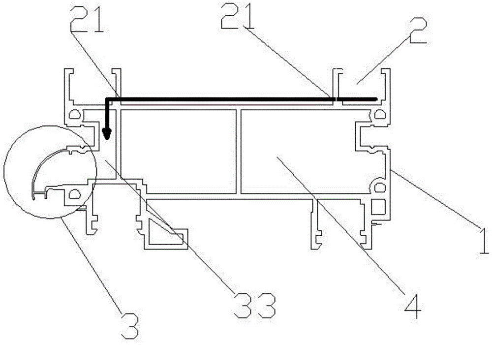
图1是本实用新型的结构示意图。Figure 1 is a schematic structural diagram of the present invention.
图2是排水部的局部放大示意图。FIG. 2 is a partially enlarged schematic view of the drainage part.
图3是本实用新型的实施示意图。FIG. 3 is a schematic view of the implementation of the present invention.
附图标号说明:1.型材;2.槽口;21.排水孔位;3.排水部;31.第一弯部;32.第二弯部;33.排水槽;34.连接部;4.腔体;5.墙体。Description of reference numerals: 1. Profile; 2. Notch; 21. Drainage hole position; 3. Drainage part; 31. First bent part; 32. Second bent part; 33. Drainage groove; . Cavity; 5. Wall.
具体实施方式Detailed ways
请参阅图1-2所示,为本实用新型实现的一种直流排水槽的型材1,该型材1的上部的左右两侧上分别开设有槽口2,其中,左侧的槽口2处的下方设有排水部3,所述排水部3包括第一弯部31、第二弯部32、连接部34以及排水槽33;所述排水槽33设置于左侧的槽口2下方,所述第一弯部31与所述第二弯部32在所述排水槽33上向外侧弯曲,所述连接部34连接所述第一弯部31和所述第二弯部32的末端位置,右侧的槽口2于槽口2内壁左侧位置上开设有排水孔位21,左侧的槽口2于槽口2内壁右侧位置上设有排水孔位21,左侧的槽口2于槽口2内壁朝向所述排水槽33方向设有排水孔位21,所述连接部34上设有排水孔位21,根据所设计的排水线路,在排水线路上的型材1上开设排水孔位21用于排水(如图3和图1的黑色粗线为水流方向)Please refer to Fig. 1-2, which is a
门窗用于隔离室内和室外的工具,经常受到风吹雨打;在装修工人在对外墙体进行批水泥砂浆或者装修工人对外墙体装饰过程中,由于操作不当中所造成的漏水、渗水渗入墙体内(如图3和图1的黑色粗线为水流方向),如不进行排水,导致水流入内墙内。故需要对门窗型材设置排水结构,而现有的门窗型材存在所设计的排水线路过长,排水效率低,还存在不利于排水的缺陷,或者,对墙体内的漏水、渗水无设置相应的排水结构。对此,易于以上所存在的问题本实用新型通过设置直流排水结构,本实用新型的排水过程:下雨时或者装修工人对外墙体装饰过程中,由于操作不当中所造成的漏水、渗水渗入墙体内,进入右侧的槽口2的雨水或者装修工人对外墙体装饰过程中,由于操作不当中所造成的漏水、渗水从右向左流向左侧的槽口2,形成直流排水的结构,雨水或者装修工人对外墙体装饰过程中,由于操作不当中所造成的漏水、渗水从左侧的槽口2流向下方的排水部3的排水槽33内,在第一弯部31、第二弯部32与连接部34形成的排水口排出(其中图1和图3中所标示的黑色粗线为水流方向),其中,所设计的第一弯部31和第二弯部32的结合限制排出水流的流向,对水流起导向作用,能够有效将墙体内的漏水、渗水排出,能够有效避免排出的水流流经型材1的表面,从而减少水流对型材1的侵蚀作用,同时本实用新型所设计的直流排水结构简单,排水线路紧凑,在生产过程中,大大减少了生产成本,更适于广泛应用。Doors and windows are used to isolate indoor and outdoor tools, and are often hit by wind and rain; in the process of decoration workers batching cement mortar on the external wall or the decoration workers decorating the external wall, water leakage and seepage caused by improper operation penetrate into the wall. In the body (the thick black line in Figure 3 and Figure 1 is the direction of water flow), if drainage is not carried out, water will flow into the inner wall. Therefore, it is necessary to set a drainage structure for the door and window profiles, but the existing door and window profiles have the design of the drainage line is too long, the drainage efficiency is low, and there are defects that are not conducive to drainage, or there is no corresponding water leakage and seepage in the wall. drainage structure. In this regard, it is easy to solve the above problems. The present invention provides a direct current drainage structure. The drainage process of the present invention: when it rains or during the process of decorating the external wall, the water leakage and seepage caused by improper operation penetrate into the wall. In the body, the rainwater entering the slot 2 on the right or the decoration workers during the external wall decoration process, due to improper operation, the water leakage and seepage flow from right to left to the slot 2 on the left, forming a direct-flow drainage structure. In the process of external wall decoration by rainwater or decoration workers, water leakage and seepage caused by improper operation flow from the slot 2 on the left to the
再结合图2所示,所述第一弯部31和所述第二弯部32在所述连接部34至少有一部分露出所述连接部34外,在水流流出第一弯部31、第二弯部32和连接部34,所形成的排水口流出时,水流由连接部34外侧的第一弯部31结合第二弯部32导流。As shown in FIG. 2 , at least a part of the first
结合图1所示,该型材1至少含有两个以上的腔体4,腔体4的设置有助于提高型材的隔热性能和隔音性能。With reference to FIG. 1 , the
以上实施方式仅仅是对本实用新型的优选实施方式进行描述,并非对本实用新型的范围进行限定,在不脱离本实用新型设计精神的前提下,本领域普通工程技术人员对本实用新型的技术方案作出的各种变形和改进,均应落入本实用新型的权利要求书确定的保护范围内。The above embodiments are only to describe the preferred embodiments of the present invention, and do not limit the scope of the present invention. On the premise of not departing from the design spirit of the present invention, ordinary engineers and technicians in the field make the technical solutions of the present invention. Various deformations and improvements should fall within the protection scope determined by the claims of the present utility model.
Claims (3)
Priority Applications (1)
| Application Number | Priority Date | Filing Date | Title |
|---|---|---|---|
| CN202020277693.XU CN212079120U (en) | 2020-03-09 | 2020-03-09 | A profile of a straight-through drainage trough |
Applications Claiming Priority (1)
| Application Number | Priority Date | Filing Date | Title |
|---|---|---|---|
| CN202020277693.XU CN212079120U (en) | 2020-03-09 | 2020-03-09 | A profile of a straight-through drainage trough |
Publications (1)
| Publication Number | Publication Date |
|---|---|
| CN212079120U true CN212079120U (en) | 2020-12-04 |
Family
ID=73560024
Family Applications (1)
| Application Number | Title | Priority Date | Filing Date |
|---|---|---|---|
| CN202020277693.XU Expired - Fee Related CN212079120U (en) | 2020-03-09 | 2020-03-09 | A profile of a straight-through drainage trough |
Country Status (1)
| Country | Link |
|---|---|
| CN (1) | CN212079120U (en) |
Cited By (1)
| Publication number | Priority date | Publication date | Assignee | Title |
|---|---|---|---|---|
| CN111188564A (en) * | 2020-03-09 | 2020-05-22 | 王亚佳 | A profile of a straight-through drainage trough |
-
2020
- 2020-03-09 CN CN202020277693.XU patent/CN212079120U/en not_active Expired - Fee Related
Cited By (1)
| Publication number | Priority date | Publication date | Assignee | Title |
|---|---|---|---|---|
| CN111188564A (en) * | 2020-03-09 | 2020-05-22 | 王亚佳 | A profile of a straight-through drainage trough |
Similar Documents
| Publication | Publication Date | Title |
|---|---|---|
| CN108843216B (en) | High-performance vertical drainage system for doors and windows | |
| CN212271941U (en) | Novel aluminum alloy door and window with high water tightness performance | |
| CN215671923U (en) | Door and window internal circulation type hidden drainage structure | |
| CN207974703U (en) | A kind of windowsill water proof building structure | |
| CN216240341U (en) | Hidden vertical drainage structure | |
| CN217975094U (en) | An aluminum profile for easy drainage | |
| CN211623075U (en) | a window frame | |
| CN109403823B (en) | Wooden house window frame water conservancy diversion structure and use its wooden house | |
| CN210888700U (en) | Outward opening window with special drainage structure | |
| CN220849491U (en) | System window with high inner side and low outer side and inner opening | |
| CN217400779U (en) | A sunken window drainage structure | |
| CN210033189U (en) | Door and window hidden drainage structure and hidden drainage adapter frame section bar | |
| CN216517696U (en) | Hidden drainage structure of system door and window | |
| CN209761181U (en) | A kind of window frame structure and opening fan of opening window | |
| CN222350595U (en) | Waterproof exterior window construction suitable for inclined walls | |
| CN221002542U (en) | Casement window with hidden hydrophobic structure | |
| CN111188564A (en) | A profile of a straight-through drainage trough | |
| CN206801347U (en) | A kind of Quick drainage aluminium profile structure | |
| CN221400231U (en) | Hidden-row high-watertight integrated casement window | |
| CN218479722U (en) | Prevention of seepage water aluminum alloy door and window convenient to installation | |
| CN205502859U (en) | Frame structure with increase material | |
| CN222772107U (en) | A kind of aluminum alloy door and window water-repellent structure | |
| CN207092831U (en) | A kind of dual chamber water drainage window frame structure | |
| CN217176386U (en) | Multi-cavity self-drainage window | |
| CN223739231U (en) | Hidden drainage window board of sliding window |
Legal Events
| Date | Code | Title | Description |
|---|---|---|---|
| GR01 | Patent grant | ||
| GR01 | Patent grant | ||
| CF01 | Termination of patent right due to non-payment of annual fee | ||
| CF01 | Termination of patent right due to non-payment of annual fee |
Granted publication date: 20201204 |