CN212078667U - A quick-assembled and disassembled expansion joint shear wall composite formwork - Google Patents
A quick-assembled and disassembled expansion joint shear wall composite formwork Download PDFInfo
- Publication number
- CN212078667U CN212078667U CN201922184070.8U CN201922184070U CN212078667U CN 212078667 U CN212078667 U CN 212078667U CN 201922184070 U CN201922184070 U CN 201922184070U CN 212078667 U CN212078667 U CN 212078667U
- Authority
- CN
- China
- Prior art keywords
- formwork
- steel square
- shear wall
- steel
- expansion joint
- Prior art date
- Legal status (The legal status is an assumption and is not a legal conclusion. Google has not performed a legal analysis and makes no representation as to the accuracy of the status listed.)
- Active
Links
Images


Landscapes
- Forms Removed On Construction Sites Or Auxiliary Members Thereof (AREA)
Abstract
本实用新型快速装拆的伸缩缝剪力墙组合模板,包括组合模板和多条对拉螺杆,组合模板包括钢模板、纵向钢方通、横向钢方通、螺母,纵向钢方通和横向钢方通分别纵横交错的固定连接在钢模板的背面,纵向钢方通和横向钢方通交叉连接处设有对拉螺孔,对拉螺孔同时贯穿纵向钢方通、横向钢方通及钢模板,螺母焊接在对拉螺孔外侧的纵向钢方通表面或横向钢方通表面,且螺母的螺孔与对拉螺孔位置相互对应,对拉螺杆可穿过组合模板的对拉螺孔而拉紧定位组合模板的位置。本实用新型组合模板适用于伸缩缝剪力墙封模,并能解决伸缩缝剪力墙模板封模紧固困难问题,降低涨模、爆模等质量问题,且可以反复使用。

The rapid assembly and disassembly of the expansion joint shear wall composite formwork of the utility model comprises a composite formwork and a plurality of pairs of tensioning screws. The square connections are criss-crossed and fixed on the back of the steel formwork, respectively. The cross-connection of the longitudinal steel square connections and the transverse steel square connections is provided with a pair of threaded holes, which simultaneously penetrate the longitudinal steel square connections, the transverse steel square connections and the steel panels. Formwork, the nut is welded on the longitudinal steel square through surface or the transverse steel square through surface outside the counter-pull screw hole, and the screw hole of the nut and the counter-pull screw hole correspond to each other, and the counter-pull screw can pass through the counter-pull screw hole of the combined template And tighten the position of the positioning combination template. The combined formwork of the utility model is suitable for the sealing of the expansion joint shear wall, and can solve the difficult problem of the sealing and fastening of the expansion joint shear wall formwork, reduce the quality problems such as mold expansion and mold explosion, and can be used repeatedly.
Description
技术领域technical field
本实用新型涉及建筑施工技术领域,特别涉及一种伸缩缝剪力墙的模板。The utility model relates to the technical field of building construction, in particular to a template for an expansion joint shear wall.
背景技术Background technique
在建工程项目,很多主体多分为两个或多个单元,在单元与单元之间设置伸缩缝,伸缩缝两次均设置为大面积的剪力墙,由于伸缩缝处间距很小,一般为200mm~300mm,故在主体浇筑时,先安装一边剪力墙模板,并加固后,后安装的剪力墙模板对拉螺杆很难穿孔加固,且拆除模板也非常困难。现有传统做法,多采用安装普通模板,然后根据常规做法用对拉螺杆拉紧。这种现有做法存在以下不足之处:1、模板安装困难:靠伸缩缝位置的模板安装,因其安装位置狭小,安装困难;2、模板拆除困难;3、模板紧固困难:靠伸缩缝位置的模板由于位置狭小,通过常规模板紧固的方式很难进行有效紧固,容易产生涨模、爆模等质量缺陷;4、此处模板,经常由于拆除工序过于困难,而使部分模板无法拆除,造成材料浪费。In construction projects, many main bodies are divided into two or more units, and expansion joints are set between the units. The expansion joints are set as large-area shear walls twice. Because the distance between the expansion joints is small, generally 200mm to 300mm, so when the main body is poured, one side of the shear wall formwork should be installed first, and after reinforcement, the latter installed shear wall formwork is difficult to perforate and reinforce the pull screw, and it is also very difficult to remove the formwork. The existing traditional method mostly adopts the installation of ordinary formwork, and then tightens it with the tension screw according to the conventional method. This existing method has the following shortcomings: 1. Difficulty in installing the formwork: the formwork at the expansion joint position is installed, which is difficult to install because of its small installation position; 2. The formwork is difficult to remove; 3. The formwork is difficult to fasten: relying on the expansion joints Due to the narrow position of the formwork, it is difficult to effectively fasten through the conventional formwork fastening method, and it is easy to produce quality defects such as mold expansion and mold explosion; 4. The formwork here is often too difficult to remove due to the difficulty of removing some formwork. dismantling, resulting in material waste.
发明内容SUMMARY OF THE INVENTION
本实用新型的目的是针对上述现有技术存在的缺陷,提供一种快速装拆的伸缩缝剪力墙组合模板,该组合模板适用于伸缩缝剪力墙封模,并能解决伸缩缝剪力墙模板封模紧固困难问题,降低涨模、爆模等质量问题,且可以反复使用。The purpose of this utility model is to aim at the defects existing in the above-mentioned prior art, and to provide a quick assembly and disassembly expansion joint shear wall composite formwork, the composite formwork is suitable for the expansion joint shear wall sealing mould, and can solve the expansion joint shear force The wall formwork is difficult to seal and fasten, and the quality problems such as mold expansion and mold explosion are reduced, and it can be used repeatedly.
本实用新型为实现上述目的采用的技术方案是:一种快速装拆的伸缩缝剪力墙组合模板,包括组合模板和多条对拉螺杆,组合模板包括钢模板、纵向钢方通、横向钢方通、螺母,纵向钢方通和横向钢方通分别纵横交错的固定连接在钢模板的背面,纵向钢方通和横向钢方通交叉连接处设有对拉螺孔,对拉螺孔同时贯穿纵向钢方通、横向钢方通及钢模板,螺母焊接在对拉螺孔外侧的纵向钢方通表面或横向钢方通表面,且螺母的螺孔与对拉螺孔位置相互对应,对拉螺杆可穿过组合模板的对拉螺孔而拉紧定位组合模板的位置。The technical scheme adopted by the utility model to achieve the above purpose is: a quick assembly and disassembly expansion joint shear wall composite formwork, comprising a composite formwork and a plurality of pairs of pulling screws, the composite formwork comprises a steel formwork, a longitudinal steel square pass, a transverse steel The square pass, nut, longitudinal steel square pass and transverse steel square pass are respectively criss-crossed and fixedly connected on the back of the steel formwork. The cross connection of the longitudinal steel square pass and the transverse steel square pass is provided with a pair of screw holes. Through the longitudinal steel square pass, the transverse steel square pass and the steel formwork, the nut is welded on the longitudinal steel square pass surface or the transverse steel square pass surface outside the counter-pull screw hole, and the screw hole of the nut and the counter-pull screw hole correspond to each other. The pull screw can pass through the pair of pull screw holes of the combined template to tighten and locate the position of the combined template.
本实用新型的进一步技术方案是:所述钢模板上端还连接有用于吊起组合模板的U形吊环。The further technical scheme of the utility model is that: the upper end of the steel formwork is also connected with a U-shaped hoisting ring for hoisting the combined formwork.
本实用新型快速装拆的伸缩缝剪力墙组合模板具有如下有益效果:The quick assembly and disassembly of the expansion joint shear wall composite formwork of the utility model has the following beneficial effects:
1、本实用新型快速装拆的伸缩缝剪力墙组合模板制作时取材方便,可采用钢、铝合金等多种材料制作;1. The quick assembly and disassembly of the expansion joint shear wall composite formwork of the present utility model is convenient to obtain materials, and can be made of various materials such as steel and aluminum alloy;
2、本实用新型快速装拆的伸缩缝剪力墙组合模板制作简单,施工现场均能按照伸缩缝剪力墙进行自制,能满足不同图纸要求;2. The quick assembly and disassembly of the expansion joint shear wall composite formwork of the present utility model is simple to manufacture, and the construction site can be self-made according to the expansion joint shear wall, which can meet the requirements of different drawings;
3、本实用新型快速装拆的伸缩缝剪力墙组合模板,模板顶端有U型吊环,可以采用吊装的方式,对模板进行整体安装拆除,降低了狭小位置安拆模板的困难和危险,装拆简便,且钢制品能周转使用,节约材料;3. The expansion joint shear wall composite formwork of the present utility model has a U-shaped lifting ring at the top of the formwork for quick assembly and disassembly. The formwork can be installed and removed as a whole by means of hoisting, which reduces the difficulty and danger of installing and disassembling the formwork in a narrow position. It is easy to disassemble, and the steel products can be used in turnaround, saving materials;
4、本实用新型快速装拆的伸缩缝剪力墙组合模板可现场制作,也可工厂化批量生产,采用工厂化批量生产可有效缩短工期,加快施工进度;4. The quick assembly and disassembly of the expansion joint shear wall composite formwork of the present utility model can be made on site, and can also be mass-produced in a factory. The use of mass-production in a factory can effectively shorten the construction period and speed up the construction progress;
5、使用本实用新型快速装拆的伸缩缝剪力墙组合模板可以大大提高伸缩缝剪力墙处模板的安拆效率,对拉螺杆可穿过孔洞旋入螺母进行组合模板的拉紧加固,加强模板的整体紧固性,防止产生涨模、爆模,进而降低混凝土质量缺陷的产生,加强模板的整体紧固性,提高混凝土浇筑质量。5. The use of the expansion joint shear wall composite template of the utility model can greatly improve the installation and removal efficiency of the template at the expansion joint shear wall. Strengthen the overall tightness of the formwork, prevent mold expansion and mold explosion, and then reduce the occurrence of concrete quality defects, strengthen the overall tightness of the formwork, and improve the quality of concrete pouring.
下面结合附图和实施例对本实用新型快速装拆的伸缩缝剪力墙组合模板作进一步的说明。The following is a further description of the composite formwork of the expansion joint shear wall for quick assembly and disassembly of the present utility model in conjunction with the accompanying drawings and embodiments.
附图说明Description of drawings
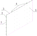
图1是本实用新型快速装拆的伸缩缝剪力墙组合模板的正面结构示意图;Fig. 1 is the front structure schematic diagram of the expansion joint shear wall composite formwork of the utility model quick assembly and disassembly;
图2是图1的局部放大视图;Fig. 2 is the partial enlarged view of Fig. 1;
图3是本实用新型快速装拆的伸缩缝剪力墙组合模板的背面结构示意图;3 is a schematic view of the back structure of the expansion joint shear wall composite formwork that can be quickly assembled and disassembled according to the present invention;
图4是图3的局部放大视图;Fig. 4 is the partial enlarged view of Fig. 3;
图5是本实用新型快速装拆的伸缩缝剪力墙组合模板作为其中一侧剪力墙模板与木模板组合安装的示意图(将组合模板示意于外侧);Figure 5 is a schematic diagram of the combined installation of the expansion joint shear wall formwork of the present utility model as a combination of one side shear wall formwork and a wooden formwork (the combined formwork is shown on the outside);
图6是本实用新型快速装拆的伸缩缝剪力墙组合模板作为其中一侧剪力墙模板与木模板组合安装的示意图(将木模板示意于外侧);Figure 6 is a schematic diagram of the combined installation of the expansion joint shear wall formwork of the present utility model as a combination of one side shear wall formwork and a wooden formwork (the wooden formwork is shown on the outside);
附图标号说明:1-钢模板,2-横向钢方通,3-纵向钢方通,4-U形吊环,5-对拉螺孔,6-螺母,7-组合模板,8-伸缩缝剪力墙,9-木模板,10-堵头模板,11-对拉螺杆,12-对拉螺杆套管。Reference number description: 1-steel formwork, 2-transverse steel square pass, 3-longitudinal steel square pass, 4-U-shaped lifting ring, 5-pair of screw holes, 6-nut, 7-combination formwork, 8-expansion joint Shear wall, 9-wood formwork, 10-plug formwork, 11-pair pull screw, 12-pair pull screw casing.
具体实施方式Detailed ways
如图1至图4所示,本实用新型快速装拆的伸缩缝剪力墙组合模板,包括组合模板和多条对拉螺杆。其中组合模板包括钢模板、纵向钢方通、横向钢方通、螺母。钢模板就是一块钢板,钢模板是根据图纸伸缩缝处剪力墙设计的尺寸,选购合适规格的钢板,本实用新型选钢模板规格800mm×2500mm×2mm作为例子,选取钢模板,按照剪力墙的尺寸进行拼接。纵向钢方通和横向钢方通分别纵横交错的固定连接在钢模板的背面,纵向钢方通和横向钢方通交叉连接处设有对拉螺孔,对拉螺孔同时贯穿纵向钢方通、横向钢方通及钢模板。在实施过程中,根据计算书,算出对拉螺杆孔间距进行放线定位(此处根据计算得出对拉螺杆间距横纵均为450mm),然后在钢模板背面根据计算书计算的背楞间距每隔450mm焊接一根纵向钢方通把钢模板固定成整体,且固定钢模板的竖向变形。其中纵向钢方通是80mm×40mm×2mm的钢方通。钢模板背面根据定位线每隔450mm焊接一根横向钢方通,增强组合模板刚度和整体性,其中横向钢方通是50mm×50mm×2mm的钢方通,直接与钢模板连接的钢方通比较粗,若是横向钢方通直接与钢模板连接,则横向钢方通采用较粗的钢方通。然后根据对拉螺孔位置,在组合模板上面开对拉螺孔,对拉螺孔同时贯穿纵向钢方通、横向钢方通及钢模板。后将螺母焊接在对拉螺孔外侧的纵向钢方通表面或横向钢方通表面,且螺母的螺孔与对拉螺孔位置相互对应。在本实施例中将螺母焊接在对拉螺孔外侧横向钢方通表面。当然若横向钢方通直接连接在钢模板背面,而纵向钢方通垂直连接在横向钢方通表面时,则将螺母焊接在对拉螺孔外侧纵向钢方通表面。对拉螺杆可穿过组合模板的对拉螺孔而拉紧定位组合模板的位置。所述钢模板上端还连接有用于吊起组合模板的U形吊环,本实施例中设有两个U形吊环,两个U形吊环分别焊接在钢模板上端的背面,且每个U形吊环同时与其中一条纵向钢方通上端两侧表面焊接固定,这样能够加强U形吊环的连接稳定性。As shown in Fig. 1 to Fig. 4, the quick assembly and disassembly of the expansion joint shear wall composite formwork of the present invention includes a composite formwork and a plurality of pairs of tensioning screws. The combined formwork includes steel formwork, longitudinal steel square pass, transverse steel square pass, and nut. The steel formwork is a piece of steel plate. The steel formwork is based on the size of the shear wall design at the expansion joint in the drawing. Choose a steel plate with a suitable specification. The size of the wall is spliced. The longitudinal steel square pass and the transverse steel square pass are respectively criss-crossed and fixedly connected on the back of the steel formwork. The cross connection of the longitudinal steel square pass and the transverse steel square pass is provided with a pair of pull screw holes, and the pair of pull screw holes pass through the longitudinal steel square pass at the same time. , Horizontal steel square pass and steel formwork. In the implementation process, according to the calculation book, calculate the spacing of the pull screw holes for pay-out positioning (here, according to the calculation, the horizontal and vertical spacing of the pull screw is 450mm), and then the back corrugation spacing calculated according to the calculation book on the back of the steel formwork Weld a longitudinal steel square pass every 450mm to fix the steel formwork as a whole, and fix the vertical deformation of the steel formwork. Among them, the longitudinal steel square pass is a steel square pass of 80mm×40mm×2mm. The back of the steel formwork is welded with a transverse steel square pass every 450mm according to the positioning line to enhance the rigidity and integrity of the combined formwork. Relatively thick, if the transverse steel square is directly connected with the steel formwork, the transverse steel square is made of thicker steel square. Then, according to the position of the screw holes, the screw holes are opened on the combined formwork, and the screw holes pass through the longitudinal steel square pass, the transverse steel square pass and the steel formwork at the same time. Afterwards, the nut is welded on the longitudinal steel square through surface or the transverse steel square through surface on the outside of the counter-pulling screw hole, and the positions of the screw holes of the nut and the counter-pulling screw holes correspond to each other. In this embodiment, the nut is welded on the lateral steel square through surface of the outer side of the threaded hole. Of course, if the transverse steel square pass is directly connected to the back of the steel formwork, and the longitudinal steel square pass is vertically connected to the surface of the transverse steel square pass, the nut shall be welded on the surface of the longitudinal steel square pass outside the counter-pull screw hole. The double-pull screw can pass through the double-pull screw hole of the combined template to tighten and locate the position of the combined template. The upper end of the steel template is also connected with a U-shaped lifting ring for hoisting the combined template. In this embodiment, two U-shaped lifting rings are provided, and the two U-shaped lifting rings are respectively welded on the back of the upper end of the steel template, and each U-shaped lifting ring is At the same time, it is welded and fixed with the two sides of the upper end of one of the longitudinal steel square passes, which can strengthen the connection stability of the U-shaped lifting ring.
施工过程可按照以下步骤实施:(1)把组合模板整体吊运到伸缩缝处的指定位置,通过在组合模板两端垫放钢方通(或仿木)与后侧放置支撑装置,初步固定组合模板;(2)安装固定伸缩缝剪力墙内侧木模板,用撬棒按墙位置线及模板的起止线调整木模板和组合模板位置,在木模板对应位置开孔并安装对拉螺杆套管,对拉螺杆从木模板一侧,穿过对拉螺杆套管并旋入组合模板的螺母中,直到对拉螺杆突出螺母50mm以上,调节至大致水平,用托线板测垂直、校正标高,使模板垂直度、水平度、标高符合设计要求,在内侧模板采用钢管就位后,立即拧紧螺栓,把组合模板与木模板拉紧固定(图5~图6);(3)侧面安装堵头模板(堵头模板也是木模板),模板接缝要严密,防止浇筑砼时漏浆;(4)然后进行混凝土浇筑;(5)混凝土强度达到拆模标准时,对伸缩缝处剪力墙模板进行拆模,拆除两边夹管器并取下短钢管,然后旋出对拉螺杆并拆除,同时拆除两端对拉螺杆和固定器,并取下长钢管,然后依次拆除内侧木模板和侧向堵头模板,最后拆除组合模板;(6)在拆除对拉螺杆时,先用工具把对拉螺栓旋松,然后通过旋转对拉螺杆,把对拉螺杆从组合模板中旋出,待所有对拉螺杆都旋出后,即拆除组合模板,吊运到指定位置放置,并进行清洁,以便下次使用。The construction process can be implemented according to the following steps: (1) Lift the combined formwork as a whole to the designated position at the expansion joint, and place the steel square pass (or imitation wood) at both ends of the combined formwork and place the support device on the rear side to initially fix it. Combined formwork; (2) Install the wooden formwork on the inner side of the fixed expansion joint shear wall, use a crowbar to adjust the position of the wooden formwork and the combined formwork according to the wall position line and the start and end lines of the formwork, open holes in the corresponding position of the wooden formwork and install the pull screw sleeve From the side of the wooden formwork, the counter-pulling screw goes through the counter-pulling screw casing and screwed into the nut of the combined formwork until the counter-pulling screw protrudes more than 50mm from the nut, adjust it to roughly horizontal, measure the vertical with a line board, and correct the elevation , so that the verticality, levelness, and elevation of the formwork meet the design requirements. After the inner formwork is in place with steel pipes, tighten the bolts immediately to tighten the combined formwork and the wooden formwork (Figure 5 to Figure 6); (3) Install the plug on the side. The head formwork (the plug formwork is also a wooden formwork), the formwork joints should be tight, to prevent the leakage of slurry when pouring concrete; (4) Then the concrete is poured; (5) When the concrete strength reaches the formwork removal standard, the shear wall formwork at the expansion joint should be installed. Remove the formwork, remove the pipe grippers on both sides and take off the short steel pipe, then unscrew the pair of pull screws and remove them, remove the two ends of the pair of pull screws and the fixer at the same time, and remove the long steel pipe, and then remove the inner wooden formwork and the lateral side in turn. Plug formwork, and finally remove the combined formwork; (6) When removing the anti-pulling screw, first use a tool to loosen the anti-pulling bolt, then rotate the anti-pulling screw, unscrew the anti-pulling screw from the combined formwork, and wait until all the correcting After the pulling screws are all unscrewed, the combined template is removed, hoisted to the designated location, and cleaned for next use.
施工时注意以下事项:(1)在木模板与组合模板交接处,须由组合模板中的钢模板包裹木模,以防板缝过大出现漏浆;(2)合模前检查钢筋、水电等预埋管件是否遗漏,正确无误;(3)模板安装完毕后,检查木模板与堵头模板、堵头模板与组合模板之间是否严密、牢固可靠,防止出现漏浆、错台现象;(4)模板安装完毕后,全面检查扣件、螺栓、斜撑是否紧固、稳定,模板拼缝及下口是否严密。Pay attention to the following matters during construction: (1) At the junction of the wooden formwork and the combined formwork, the wooden formwork must be wrapped by the steel formwork in the combined formwork to prevent the leakage of slurry due to excessive slab joints; (2) Before closing the formwork, check the steel bars, water and electricity (3) After the installation of the formwork is completed, check whether the wood formwork and the plug formwork, the plug formwork and the combined formwork are tight, firm and reliable, so as to prevent the phenomenon of slurry leakage and misplacement; ( 4) After the template is installed, comprehensively check whether the fasteners, bolts, and diagonal braces are fastened and stable, and whether the template joints and lower openings are tight.
以上实施例仅为本实用新型的较佳实施例,本实用新型的结构并不限于上述实施例列举的形式,凡在本实用新型的精神和原则之内所作的任何修改、等同替换等,均应包含在本实用新型的保护范围之内。The above embodiments are only preferred embodiments of the present utility model, and the structure of the present utility model is not limited to the forms listed in the above-mentioned embodiments. Any modifications, equivalent replacements, etc. made within the spirit and principles of the present utility model are It should be included within the protection scope of the present invention.
Claims (2)
Priority Applications (1)
| Application Number | Priority Date | Filing Date | Title |
|---|---|---|---|
| CN201922184070.8U CN212078667U (en) | 2019-12-09 | 2019-12-09 | A quick-assembled and disassembled expansion joint shear wall composite formwork |
Applications Claiming Priority (1)
| Application Number | Priority Date | Filing Date | Title |
|---|---|---|---|
| CN201922184070.8U CN212078667U (en) | 2019-12-09 | 2019-12-09 | A quick-assembled and disassembled expansion joint shear wall composite formwork |
Publications (1)
| Publication Number | Publication Date |
|---|---|
| CN212078667U true CN212078667U (en) | 2020-12-04 |
Family
ID=73555787
Family Applications (1)
| Application Number | Title | Priority Date | Filing Date |
|---|---|---|---|
| CN201922184070.8U Active CN212078667U (en) | 2019-12-09 | 2019-12-09 | A quick-assembled and disassembled expansion joint shear wall composite formwork |
Country Status (1)
| Country | Link |
|---|---|
| CN (1) | CN212078667U (en) |
Cited By (2)
| Publication number | Priority date | Publication date | Assignee | Title |
|---|---|---|---|---|
| CN110821147A (en) * | 2019-12-09 | 2020-02-21 | 广西建工集团第三建筑工程有限责任公司 | Expansion joint shear wall combination template capable of being assembled and disassembled quickly |
| CN116201350A (en) * | 2023-03-21 | 2023-06-02 | 中国建筑第六工程局有限公司 | Steel-concrete combined large formwork system construction method for bare concrete construction |
-
2019
- 2019-12-09 CN CN201922184070.8U patent/CN212078667U/en active Active
Cited By (2)
| Publication number | Priority date | Publication date | Assignee | Title |
|---|---|---|---|---|
| CN110821147A (en) * | 2019-12-09 | 2020-02-21 | 广西建工集团第三建筑工程有限责任公司 | Expansion joint shear wall combination template capable of being assembled and disassembled quickly |
| CN116201350A (en) * | 2023-03-21 | 2023-06-02 | 中国建筑第六工程局有限公司 | Steel-concrete combined large formwork system construction method for bare concrete construction |
Similar Documents
| Publication | Publication Date | Title |
|---|---|---|
| CN104895318B (en) | Aluminum alloy template system and construction method of same | |
| CN204983634U (en) | Y shape split bolt reinforced structure of waterproof position concrete wall bight form setting | |
| CN111472461B (en) | Steel pipe concrete column steel reinforced concrete beam ring beam node formwork reinforcement and method | |
| CN217780474U (en) | Large-scale prefabricated case roof beam hoist and mount crack control device | |
| CN110821147A (en) | Expansion joint shear wall combination template capable of being assembled and disassembled quickly | |
| CN210976588U (en) | Template reinforcing system for double shear walls at deformation joint | |
| CN210289132U (en) | Cross-shaped constructional column combined type aluminum alloy template assembly | |
| CN115522732A (en) | Reinforcing device for large-section concrete beam and construction method | |
| CN214834809U (en) | A formwork-free jig | |
| CN211446999U (en) | Foundation bolt positioning die | |
| CN110258864A (en) | A kind of basement shear wall exempts from punching template construction method | |
| CN114809591A (en) | Reinforcing construction method for aluminum alloy templates of wall bodies on two sides of long and narrow expansion joint | |
| CN210685368U (en) | Convenient reinforcing complete die set for concrete wall formworks on two sides of deformation joint | |
| CN205171999U (en) | Narrow expansion joint of shear force wall template | |
| CN111622494A (en) | Hole-leaving-free construction method for shear wall light steel keel template | |
| CN220246891U (en) | Pit forming integrated template device suitable for foundation pit | |
| CN112443159A (en) | Template tapping-free clamp and construction method thereof | |
| CN210025768U (en) | A operation platform system for caisson template installation | |
| CN209653365U (en) | Tool type wall fitting | |
| CN112459467A (en) | Deformation joint wall formwork and cast-in-place shear wall construction method | |
| CN118958659A (en) | A construction method for a post-casting belt top plate support-free formwork system | |
| CN118049049A (en) | Universal column hoop and construction method of cast-in-place special-shaped frame column using the universal column hoop | |
| CN104453235A (en) | Convertor station firewall construction technology | |
| CN205577401U (en) | External rectangular cross section concrete column template fastener of pull rod | |
| CN117071877A (en) | A construction method for shear wall formwork on both sides of an expansion joint |
Legal Events
| Date | Code | Title | Description |
|---|---|---|---|
| GR01 | Patent grant | ||
| GR01 | Patent grant | ||
| PP01 | Preservation of patent right |
Effective date of registration: 20250822 Granted publication date: 20201204 |
|
| PP01 | Preservation of patent right |