CN212064030U - Wired communication and wireless communication conversion device - Google Patents
Wired communication and wireless communication conversion device Download PDFInfo
- Publication number
- CN212064030U CN212064030U CN202021126231.4U CN202021126231U CN212064030U CN 212064030 U CN212064030 U CN 212064030U CN 202021126231 U CN202021126231 U CN 202021126231U CN 212064030 U CN212064030 U CN 212064030U
- Authority
- CN
- China
- Prior art keywords
- fixedly installed
- wireless communication
- limit
- casing
- conversion device
- Prior art date
- Legal status (The legal status is an assumption and is not a legal conclusion. Google has not performed a legal analysis and makes no representation as to the accuracy of the status listed.)
- Expired - Fee Related
Links
Images


Landscapes
- Casings For Electric Apparatus (AREA)
- Transceivers (AREA)
Abstract
本实用新型公开了有线通讯与无线通讯转换装置,包括安装块,安装块的顶端开设有安装槽,安装槽的内部嵌设有转换器壳体,且转换器壳体与安装槽之间安装有卡合机构,转换器壳体由下壳体和上壳体组成,下壳体的一侧固定安装有多个线缆插口,下壳体的另一侧固定安装有多个信号收发器,下壳体内部的底端固定安装有电路板,电路板的表面分别设置有接口通讯模块和无线通讯模块,且线缆插口与接口通讯模块电性连接。本实用新型通过电路板表面设有的接口通讯模块与线缆插口连接,通过电路板表面的设有的无线通讯模块与信号收发器电性连接,从而实现有线通讯与无线通讯的相互转换,提高通讯效率。
The utility model discloses a wired communication and wireless communication conversion device, which comprises an installation block, an installation groove is formed at the top of the installation block, a converter casing is embedded in the installation groove, and a converter casing is installed between the converter casing and the installation groove. The clamping mechanism, the converter casing is composed of a lower casing and an upper casing, a plurality of cable sockets are fixedly installed on one side of the lower casing, and a plurality of signal transceivers are fixedly installed on the other side of the lower casing. A circuit board is fixedly installed at the bottom end inside the casing, an interface communication module and a wireless communication module are respectively arranged on the surface of the circuit board, and the cable socket is electrically connected with the interface communication module. The utility model is connected with the cable socket through the interface communication module provided on the surface of the circuit board, and is electrically connected with the signal transceiver through the wireless communication module provided on the surface of the circuit board, thereby realizing the mutual conversion between wired communication and wireless communication, and improving the communication efficiency.
Description
技术领域technical field
本实用新型涉及通讯技术领域,特别涉及有线通讯与无线通讯转换装置。The utility model relates to the technical field of communication, in particular to a conversion device for wired communication and wireless communication.
背景技术Background technique
通讯,指人与人或人与自然之间通过某种行为或媒介进行的信息交流与传递,从广义上指需要信息的双方或多方在不违背各自意愿的情况下采用任意方法,任意媒质,将信息从某方准确安全地传送到另方。Communication refers to the exchange and transmission of information between people or between people and nature through a certain behavior or medium. In a broad sense, it refers to the use of any method, any medium, and Accurately and securely transmit information from one party to another.
目前的通讯为了通讯的流畅度,一般在家用网络中将有线通讯通过转换器转换为无线通讯,便于实现更多的人使用,但是目前的通讯转换器在使用过程中,壳体一般为封死状态,便于对通讯转换设备内部的电路进行检修,同时目前的通讯转换设备一般通过螺钉进行安装,影响通讯转换设备的安装效率。In the current communication, for the smoothness of communication, the wired communication is generally converted into wireless communication through the converter in the home network, which is convenient for more people to use. However, during the use of the current communication converter, the casing is generally sealed. It is convenient to overhaul the circuit inside the communication conversion equipment. Meanwhile, the current communication conversion equipment is generally installed by screws, which affects the installation efficiency of the communication conversion equipment.
实用新型内容Utility model content
本实用新型的目的在于提供有线通讯与无线通讯转换装置,以解决上述背景技术中提出的问题。The purpose of the present invention is to provide a wired communication and wireless communication conversion device to solve the above-mentioned problems in the background art.
为实现上述目的,本实用新型提供如下技术方案:有线通讯与无线通讯转换装置,包括安装块,所述安装块的顶端开设有安装槽,所述安装槽的内部嵌设有转换器壳体,且所述转换器壳体与安装槽之间安装有卡合机构,所述转换器壳体由下壳体和上壳体组成,所述下壳体的一侧固定安装有多个线缆插口,所述下壳体的另一侧固定安装有多个信号收发器,所述下壳体内部的底端固定安装有电路板,所述电路板的表面分别设置有接口通讯模块和无线通讯模块,且所述线缆插口与接口通讯模块电性连接,所述信号收发器与无线通讯模块电性连接,所述下壳体顶端的两侧均开设有卡槽,两个所述卡槽的一侧均开设有限位孔,所述上壳体底端的两侧均固定安装有卡块,两个所述卡块与对应的卡槽卡合连接,两个所述卡块的一侧均开设有T型槽,两个所述T型槽的一侧槽壁均固定安装有多个第三限位弹簧,多个所述第三限位弹簧的一端固定安装有限位板,两个所述限位板的一侧固定安装有限位柱,两个所述限位柱与对应的限位孔穿插连接。In order to achieve the above purpose, the present utility model provides the following technical solutions: a wired communication and wireless communication conversion device, comprising a mounting block, the top of the mounting block is provided with a mounting groove, and a converter housing is embedded in the interior of the mounting groove, A snap mechanism is installed between the converter housing and the installation slot, the converter housing is composed of a lower housing and an upper housing, and a plurality of cable sockets are fixedly installed on one side of the lower housing , a plurality of signal transceivers are fixedly installed on the other side of the lower casing, a circuit board is fixedly installed at the bottom end inside the lower casing, and the surface of the circuit board is respectively provided with an interface communication module and a wireless communication module , and the cable socket is electrically connected to the interface communication module, the signal transceiver is electrically connected to the wireless communication module, the top of the lower casing is provided with card slots on both sides, and the two card slots are Limiting holes are provided on one side, and clamping blocks are fixedly installed on both sides of the bottom end of the upper casing. There are T-shaped grooves, a plurality of third limit springs are fixedly installed on one side of the groove walls of the two T-shaped grooves, and a limit plate is fixedly installed at one end of the plurality of third limit springs, and the two One side of the limit plate is fixedly installed with limit posts, and two of the limit posts are inserted and connected with the corresponding limit holes.
优选的,所述卡合机构包括四个U型块,所述下壳体的两侧均开设有两个U型槽,四个所述U型槽的内部均嵌设有U型块,四个所述U型块的一侧槽壁均固定安装有多个第一限位弹簧,多个所述第一限位弹簧的一端与对应U型槽的一侧槽壁固定连接,所述安装槽的两侧槽壁均开设有两个固定孔,四个所述U型块的一端与对应的固定孔穿插连接。Preferably, the engaging mechanism includes four U-shaped blocks, two U-shaped grooves are opened on both sides of the lower casing, and U-shaped blocks are embedded in the interior of the four U-shaped grooves. A plurality of first limit springs are fixedly installed on one side groove wall of each of the U-shaped blocks, and one end of the plurality of first limit springs is fixedly connected with the side groove wall of the corresponding U-shaped groove. Two fixing holes are opened on both sides of the groove wall, and one end of the four U-shaped blocks is inserted and connected with the corresponding fixing holes.
优选的,所述下壳体两边侧等距开设有多个散热孔,多个所述散热孔的内部均固定安装有防尘网。Preferably, a plurality of heat dissipation holes are equidistantly provided on both sides of the lower casing, and dust-proof nets are fixedly installed in the interiors of the plurality of heat dissipation holes.
优选的,所述下壳体与上壳体之间的连接处贴设有密封条,所述密封条为橡胶材质。Preferably, a sealing strip is attached to the joint between the lower casing and the upper casing, and the sealing strip is made of rubber.
优选的,所述转换器壳体底端的尺寸与安装槽的内径相匹配,且所述安装槽的内壁开设有均匀分布的防滑纹。Preferably, the size of the bottom end of the converter housing matches the inner diameter of the installation groove, and the inner wall of the installation groove is provided with evenly distributed anti-skid lines.
优选的,所述上壳体底端的中部固定安装有两个第二限位弹簧,两个所述第二限位弹簧的一端均固定安装有L型块,两个所述L型块与电路板两侧接触连接。Preferably, two second limit springs are fixedly installed in the middle of the bottom end of the upper casing, and L-shaped blocks are fixedly installed at one end of the two second limit springs, and the two L-shaped blocks are connected to the circuit Contact connections on both sides of the board.
优选的,所述限位柱的尺寸与限位孔的内径相匹配。Preferably, the size of the limiting column matches the inner diameter of the limiting hole.
本实用新型的技术效果和优点:Technical effects and advantages of the present utility model:
(1)通过电路板表面设有的接口通讯模块与线缆插口连接,通过电路板表面的设有的无线通讯模块与信号收发器电性连接,从而实现有线通讯与无线通讯的相互转换,提高通讯效率;(1) The interface communication module provided on the surface of the circuit board is connected to the cable socket, and the wireless communication module provided on the surface of the circuit board is electrically connected to the signal transceiver, so as to realize the mutual conversion of wired communication and wireless communication, and improve the communication efficiency;
(2)转换器壳体由上壳体壳下壳体组成,上壳体与下壳体之间通过卡块与卡槽卡合连接,并通过限位柱与限位孔进行穿插,便于上壳体与下壳体之间的安装和拆卸,从而方便对转换器壳体内部的电路板进行检修;(2) The converter casing is composed of an upper casing and a lower casing. The upper casing and the lower casing are connected by a clamping block and a clamping slot, and are interspersed through a limit column and a limit hole, which is convenient for the upper and lower shells. Installation and disassembly between the casing and the lower casing, so as to facilitate the maintenance of the circuit board inside the converter casing;
(3)转换器壳体与安装块之间通过U型块与U型槽嵌设,便于转换器的安装,提高转换器的安装效率。(3) U-shaped blocks and U-shaped grooves are embedded between the converter housing and the installation block, which facilitates the installation of the converter and improves the installation efficiency of the converter.
附图说明Description of drawings
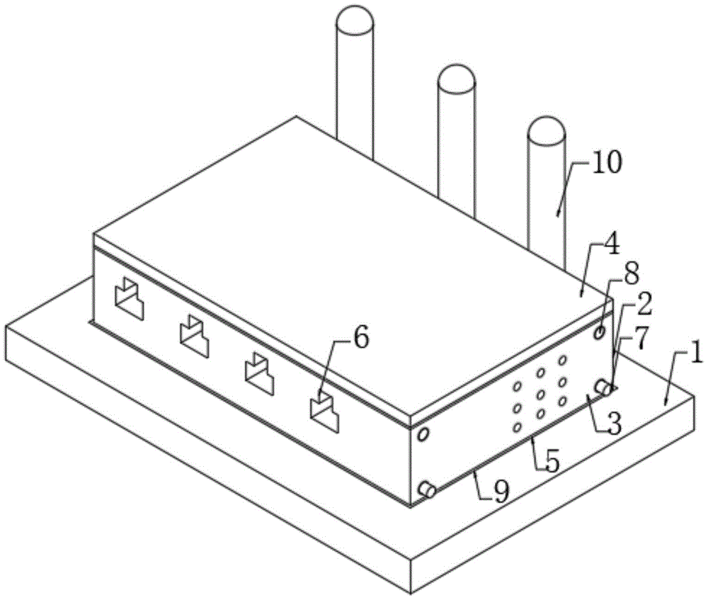
图1为本实用新型结构示意图。Figure 1 is a schematic structural diagram of the utility model.
图2为本实用新型截面结构示意图。FIG. 2 is a schematic diagram of the cross-sectional structure of the utility model.
图3为本实用新型转换器壳体内部结构示意图。FIG. 3 is a schematic diagram of the internal structure of the converter housing of the present invention.
图4为本实用新型图2A处放大图。FIG. 4 is an enlarged view of FIG. 2A of the present utility model.
图5为本实用新型图3B处放大图。FIG. 5 is an enlarged view of FIG. 3B of the present invention.
图中:1、安装块;2、转换器壳体;3、下壳体;4、上壳体;5、散热孔;6、线缆插口;7、U型块;8、限位柱;9、安装槽;10、信号收发器; 11、固定孔;12、U型槽;13、第一限位弹簧;14、电路板;15、第二限位弹簧;16、L型块;17、卡块;18、T型槽;19、限位板;20、第三限位弹簧。In the figure: 1. Mounting block; 2. Converter housing; 3. Lower housing; 4. Upper housing; 5. Heat dissipation hole; 6. Cable socket; 7. U-shaped block; 8. Limiting post; 9. Installation slot; 10. Signal transceiver; 11. Fixing hole; 12. U-shaped slot; 13. First limit spring; 14. Circuit board; 15. Second limit spring; 16. L-shaped block; 17 , block; 18, T-slot; 19, limit plate; 20, the third limit spring.
具体实施方式Detailed ways
下面将结合本实用新型实施例中的附图,对本实用新型实施例中的技术方案进行清楚、完整地描述,显然,所描述的实施例仅仅是本实用新型一部分实施例,而不是全部的实施例。基于本实用新型中的实施例,本领域普通技术人员在没有做出创造性劳动前提下所获得的所有其他实施例,都属于本实用新型保护的范围。The technical solutions in the embodiments of the present utility model will be clearly and completely described below with reference to the accompanying drawings in the embodiments of the present utility model. Obviously, the described embodiments are only a part of the embodiments of the present utility model, rather than all the implementations. example. Based on the embodiments of the present invention, all other embodiments obtained by those of ordinary skill in the art without creative work fall within the protection scope of the present invention.
本实用新型提供了如图1-5所示的有线通讯与无线通讯转换装置,包括安装块1,安装块1的顶端开设有安装槽9,安装槽9的内部嵌设有转换器壳体2,且转换器壳体2与安装槽9之间安装有卡合机构,转换器壳体2 由下壳体3和上壳体4组成,下壳体3的一侧固定安装有多个线缆插口6,通过线缆插口6与外接有线通讯线缆连接,下壳体3的另一侧固定安装有多个信号收发器10,通过信号收发器10转换为无线信号,下壳体3内部的底端固定安装有电路板14,电路板14的表面分别设置有接口通讯模块和无线通讯模块,且线缆插口与接口通讯模块电性连接,信号收发器10与无线通讯模块电性连接,下壳体3顶端的两侧均开设有卡槽,两个卡槽的一侧均开设有限位孔,上壳体4底端的两侧均固定安装有卡块17,两个卡块17 与对应的卡槽卡合连接,通过卡块17与卡槽卡合,便于下壳体3与上壳体 4之间卡合,两个卡块17的一侧均开设有T型槽18,两个T型槽18的一侧槽壁均固定安装有多个第三限位弹簧20,多个第三限位弹簧20的一端固定安装有限位板19,两个限位板19的一侧固定安装有限位柱8,两个限位柱8与对应的限位孔穿插连接,限位柱8的尺寸与限位孔的内径相匹配,通过第三限位弹簧20控制限位柱8的伸缩,便于对卡块17进行固定;The utility model provides a wired communication and wireless communication conversion device as shown in Figures 1-5, comprising a mounting block 1, a
卡合机构包括四个U型块7,下壳体3的两侧均开设有两个U型槽12,四个U型槽12的内部均嵌设有U型块7,四个U型块7的一侧槽壁均固定安装有多个第一限位弹簧13,多个第一限位弹簧13的一端与对应U型槽 12的一侧槽壁固定连接,安装槽9的两侧槽壁均开设有两个固定孔11,四个U型块7的一端与对应的固定孔11穿插连接,通过第一限位弹簧13控制U型块7的伸缩,通过U型块7的伸缩,便于使U型块7与固定孔11的嵌设和分离,从而实现转换器壳体2的安装和拆卸;The engaging mechanism includes four
转换器壳体2底端的尺寸与安装槽9的内径相匹配,且安装槽9的内壁开设有均匀分布的防滑纹,通过开设的防滑纹,增加安装槽9与转换器壳体2之间的摩擦力,保证转换器壳体2安装牢固,下壳体3两边侧等距开设有多个散热孔5,多个散热孔5的内部均固定安装有防尘网,通过开设的散热孔5便于散热,下壳体3与上壳体4之间的连接处贴设有密封条,密封条为橡胶材质,通过设有的密封条,保证连接处的密封性,上壳体4 底端的中部固定安装有两个第二限位弹簧15,两个第二限位弹簧15的一端均固定安装有L型块16,两个L型块16与电路板14两侧接触连接。The size of the bottom end of the converter housing 2 matches the inner diameter of the
本实用新型工作原理:当需要使用该有限通讯与无线通讯转换装置时,首先人为的按动连接下壳体3两侧的两个U型块7嵌设至U型槽12的内部,接着人为将转换器壳体2嵌设至安装槽9的内部,并保证U型块7的一端与固定孔11位置对正,然后人为的放开U型块7,U型块7通过第一限位弹簧13嵌设至固定孔11的内部,完成转换器壳体2的安装,然后人为的将有线线缆插入至线缆插口6中内部,通过转换器壳体2内部电路板14表面安装的接口通讯模块和无线通讯模块实现有线通讯与无线通讯之间的转换,当需要对转换器壳体2内部的电路板14进行检修时,人为的通过外接插柱挤压限位孔内部的四个限位柱8,使四个限位柱8与对应限位孔分离,然后使卡块17与卡槽分离,完成下壳体3和上壳体4的分离,接着对电路板14进行检修。The working principle of the utility model: when the limited communication and wireless communication conversion device needs to be used, firstly, the two
在本实用新型的描述中,除非另有明确的规定和限定,术语“设置”、“安装”、“相连”、“连接”、“固定”应做广义理解,例如,可以是固定连接,也可以是可拆卸连接,或成一体;可以是机械连接,也可以是电连接;可以是直接相连,也可以通过中间媒介间接相连,可以是两个元件内部的连通或两个元件的相互作用关系。对于本领域的普通技术人员而言,可以具体情况理解上述术语在本实用新型中的具体含义。In the description of the present invention, unless otherwise expressly specified and limited, the terms "arrangement", "installation", "connection", "connection" and "fixation" should be interpreted in a broad sense, for example, it may be a fixed connection, or It can be a detachable connection or an integral body; it can be a mechanical connection or an electrical connection; it can be a direct connection or an indirect connection through an intermediate medium, and it can be the internal communication between two elements or the interaction between the two elements. . For those of ordinary skill in the art, the specific meanings of the above terms in the present invention can be understood in specific situations.
本实用新型使用到的标准零件均可以从市场上购买,异形件根据说明书的和附图的记载均可以进行订制。The standard parts used in the utility model can be purchased from the market, and the special-shaped parts can be customized according to the description in the description and the drawings.
尽管已经示出和描述了本实用新型的实施例,对于本领域的普通技术人员而言,可以理解在不脱离本实用新型的原理和精神的情况下可以对这些实施例进行多种变化、修改、替换和变型,本实用新型的范围由所附权利要求及其等同物限定。Although the embodiments of the present invention have been shown and described, it will be understood by those skilled in the art that various changes and modifications can be made to these embodiments without departing from the principles and spirit of the present invention , alternatives and modifications, the scope of the present invention is defined by the appended claims and their equivalents.
Claims (7)
Priority Applications (1)
| Application Number | Priority Date | Filing Date | Title |
|---|---|---|---|
| CN202021126231.4U CN212064030U (en) | 2020-06-17 | 2020-06-17 | Wired communication and wireless communication conversion device |
Applications Claiming Priority (1)
| Application Number | Priority Date | Filing Date | Title |
|---|---|---|---|
| CN202021126231.4U CN212064030U (en) | 2020-06-17 | 2020-06-17 | Wired communication and wireless communication conversion device |
Publications (1)
| Publication Number | Publication Date |
|---|---|
| CN212064030U true CN212064030U (en) | 2020-12-01 |
Family
ID=73513845
Family Applications (1)
| Application Number | Title | Priority Date | Filing Date |
|---|---|---|---|
| CN202021126231.4U Expired - Fee Related CN212064030U (en) | 2020-06-17 | 2020-06-17 | Wired communication and wireless communication conversion device |
Country Status (1)
| Country | Link |
|---|---|
| CN (1) | CN212064030U (en) |
Cited By (1)
| Publication number | Priority date | Publication date | Assignee | Title |
|---|---|---|---|---|
| CN113132208A (en) * | 2021-03-24 | 2021-07-16 | 南京物联传感技术有限公司 | 485 wired serial port signal and Zigbee wireless signal's adapter |
-
2020
- 2020-06-17 CN CN202021126231.4U patent/CN212064030U/en not_active Expired - Fee Related
Cited By (2)
| Publication number | Priority date | Publication date | Assignee | Title |
|---|---|---|---|---|
| CN113132208A (en) * | 2021-03-24 | 2021-07-16 | 南京物联传感技术有限公司 | 485 wired serial port signal and Zigbee wireless signal's adapter |
| CN113132208B (en) * | 2021-03-24 | 2023-10-27 | 南物科城传感技术(广州)有限公司 | An adapter between 485 wired serial port signal and Zigbee wireless signal |
Similar Documents
| Publication | Publication Date | Title |
|---|---|---|
| CN206341514U (en) | A kind of integral plug-in type controller for electric vehicle | |
| CN206077883U (en) | An electric vehicle controller | |
| CN205027941U (en) | Optical module | |
| CN203279430U (en) | Small pluggable module heat dissipation structure | |
| CN204634223U (en) | A power supply and waterproof power supply structure | |
| CN215417803U (en) | Heat radiation structure of mobile phone charger transformer | |
| CN213276030U (en) | Novel heat radiation structure photovoltaic module | |
| CN221652183U (en) | Network information junction box | |
| CN205212376U (en) | A cell body heat radiation structure for bus duct | |
| CN221994456U (en) | Novel photoelectric coupler | |
| CN210431491U (en) | Mobile phone chip plug-in structure | |
| CN209461725U (en) | A kind of cable connected structure of network perimeter security safeguard | |
| CN113132208B (en) | An adapter between 485 wired serial port signal and Zigbee wireless signal | |
| CN209283588U (en) | A kind of die casting aluminium controller for electric vehicle | |
| CN218897383U (en) | Intelligent road test equipment terminal shell | |
| CN218070163U (en) | Multi-frequency combiner | |
| CN215935199U (en) | Electronic photo album converter | |
| CN219457340U (en) | An easy-to-install transformer mounting shell | |
| CN222073316U (en) | Dampproofing gateway box | |
| CN209982938U (en) | A power supply structure with a highly sealed enclosure | |
| CN213960636U (en) | Network coding equipment | |
| CN211417010U (en) | A charging pile communication interface based on power carrier technology | |
| CN210490014U (en) | Four-in-one TYPE-C converter | |
| CN216312622U (en) | A bus duct with a structure that is convenient for splicing and is sealed and waterproof | |
| CN223167685U (en) | A data transmission interface based on information security |
Legal Events
| Date | Code | Title | Description |
|---|---|---|---|
| GR01 | Patent grant | ||
| GR01 | Patent grant | ||
| CF01 | Termination of patent right due to non-payment of annual fee | ||
| CF01 | Termination of patent right due to non-payment of annual fee |
Granted publication date: 20201201 |