CN212063291U - A quick welding set of moulding formula for transmission cable intermediate head - Google Patents
A quick welding set of moulding formula for transmission cable intermediate head Download PDFInfo
- Publication number
- CN212063291U CN212063291U CN202020986501.2U CN202020986501U CN212063291U CN 212063291 U CN212063291 U CN 212063291U CN 202020986501 U CN202020986501 U CN 202020986501U CN 212063291 U CN212063291 U CN 212063291U
- Authority
- CN
- China
- Prior art keywords
- groove
- die plate
- face
- right directions
- transmission cable
- Prior art date
- Legal status (The legal status is an assumption and is not a legal conclusion. Google has not performed a legal analysis and makes no representation as to the accuracy of the status listed.)
- Active
Links
Images


Landscapes
- Processing Of Terminals (AREA)
Abstract
本实用新型提供一种用于输电电缆中间接头的模塑式快速熔接装置,包括装置本体,所述装置本体底部设置有左右方向的凹槽模具板,且凹槽模具板顶部对接安装有左右方向的凸块模具板;所述凸块模具板和凹槽模具板之间左右端面中心均插入安装有左右方向的输电电缆芯,且凸块模具板和凹槽模具板之间前后均插入安装有左右方向的对接固定块;所述凸块模具板和凹槽模具板前后端面中间均通过螺栓固定安装有左右方向的便携开模柄。凸块模具板的设置,方便放置在凹槽模具板顶部对接并通过插入前后对接固定块进行对接固定,方便可拆浇筑筒通过螺纹固定安装和拆卸更换,方便浇注时通过顶部左右两侧出气孔进行排气,解决了单孔注入容易存在气泡影响使用的问题。
The utility model provides a molding-type quick welding device for an intermediate joint of a power transmission cable, comprising a device body, the bottom of the device body is provided with a left-right direction groove die plate, and the top of the groove die plate is butt-mounted with a left-right direction The bump mold plate; the center of the left and right end faces between the bump mold plate and the groove mold plate are inserted and installed with the power transmission cable core in the left and right directions, and the front and rear of the bump mold plate and the groove mold plate are inserted and installed. The docking and fixing blocks in the left and right directions; the front and rear surfaces of the convex die plate and the groove die plate are fixed and installed with a portable die opening handle in the left and right directions by bolts. The setting of the convex mold plate is convenient for placing it on the top of the groove mold plate for docking and docking and fixing by inserting the front and rear butt-fixing blocks, which is convenient for the removable pouring cylinder to be installed, disassembled and replaced by screwing, and it is convenient for pouring through the air outlets on the left and right sides of the top. Exhaust is carried out to solve the problem that air bubbles are easy to affect the use of single-hole injection.
Description
技术领域technical field
本实用新型属于熔接装置技术领域,尤其涉及一种用于输电电缆中间接头的模塑式快速熔接装置。The utility model belongs to the technical field of welding devices, in particular to a molding type quick welding device used for an intermediate joint of a power transmission cable.
背景技术Background technique
电力电缆是用于传输和分配电能的电缆,电力电缆常用于城市地下电网、发电站引出线路、工矿企业内部供电及过江海水下输电线。在电力线路中,电缆所占比重正逐渐增加。电力电缆是在电力系统的主干线路中用以传输和分配大功率电能的电缆产品,包括各种绝缘的电力电缆。Power cables are cables used to transmit and distribute electrical energy. Power cables are often used in urban underground power grids, power station lead-out lines, internal power supply in industrial and mining enterprises, and underwater transmission lines across rivers and seas. In power lines, the proportion of cables is gradually increasing. Power cables are cable products used to transmit and distribute high-power electrical energy in the main lines of the power system, including various insulated power cables.
基于上述,本发明人发现,现有的模塑式熔接装置不方便快速安装和脱模取下,且不方便携带移动至需要使用的位置,同时单孔注入不方便排出内部空气容易存在气泡影响使用。Based on the above, the inventors found that the existing mold fusion splicing device is inconvenient for quick installation and demolding and removal, and it is inconvenient to carry and move to the position where it needs to be used. Meanwhile, it is inconvenient for single-hole injection to discharge the internal air and is easily affected by air bubbles. use.
于是,有鉴于此,针对现有的结构及缺失予以研究改良,提供一种用于输电电缆中间接头的模塑式快速熔接装置,以期达到更具有更加实用价值性的目的。Therefore, in view of this, the existing structure and defects are studied and improved, and a mold-type quick welding device for the intermediate joint of a power transmission cable is provided, in order to achieve a more practical purpose.
实用新型内容Utility model content
为了解决上述技术问题,本实用新型提供一种用于输电电缆中间接头的模塑式快速熔接装置,以解决现有的模塑式熔接装置不方便快速安装和脱模取下,且不方便携带移动至需要使用的位置,同时单孔注入不方便排出内部空气容易存在气泡影响使用的问题。In order to solve the above technical problems, the present utility model provides a molding type quick welding device for the intermediate joint of a power transmission cable, so as to solve the problem that the existing molding type welding device is inconvenient for quick installation and demoulding and removal, and it is inconvenient to carry Move it to the position where it needs to be used, and at the same time, it is inconvenient for single-hole injection to discharge the internal air, and there is a problem that air bubbles affect the use.
本实用新型用于输电电缆中间接头的模塑式快速熔接装置的目的与功效,由以下具体技术手段所达成:The purpose and effect of the utility model for the molding type quick welding device for the intermediate joint of the power transmission cable are achieved by the following specific technical means:
一种用于输电电缆中间接头的模塑式快速熔接装置,包括装置本体,所述装置本体底部设置有左右方向的凹槽模具板,且凹槽模具板顶部对接安装有左右方向的凸块模具板;所述凸块模具板和凹槽模具板之间左右端面中心均插入安装有左右方向的输电电缆芯,且凸块模具板和凹槽模具板之间前后均插入安装有左右方向的对接固定块;所述凸块模具板和凹槽模具板前后端面中间均通过螺栓固定安装有左右方向的便携开模柄,且凸块模具板顶部中间固定安装有上下方向的可拆浇筑筒。A mold-type quick welding device for intermediate joints of power transmission cables, comprising a device body, the bottom of the device body is provided with a groove die plate in the left and right directions, and the top of the groove die plate is butt-mounted with a left and right direction bump die plate; the center of the left and right end faces between the bump die plate and the groove die plate is inserted and installed with the power transmission cable core in the left and right directions, and the front and rear of the bump die plate and the groove die plate are inserted and installed with the butt joints in the left and right directions. Fixed block; the front and rear surfaces of the convex die plate and the groove die plate are fixedly installed with left and right portable mold opening handles through bolts, and the top of the convex die plate is fixedly installed with an up and down detachable pouring cylinder.
进一步的,所述凹槽模具板顶部端面前后均开设有左右方向的凸形限位槽,且凹槽模具板顶部端面中间前后均开设有左右方向的插入对接槽,凹槽模具板顶部端面中间左右两侧均开设有左右方向的半圆芯线槽,凹槽模具板顶部端面中间开设有左右方向的浇筑半圆槽。Further, the front and rear of the top end of the groove die plate are provided with left-right direction convex limit grooves, and the front and rear of the top end face of the groove die plate are provided with left and right insertion butt grooves, and the middle of the top end face of the groove die plate is provided with The left and right sides are provided with semi-circular core wire grooves in the left and right directions, and the middle of the top end face of the groove die plate is provided with a pouring semi-circular groove in the left and right directions.
进一步的,所述凸块模具板底部端面前后均开设有左右方向的凸形限位槽,且凸块模具板底部端面中间前后均开设有左右方向的插入对接块,凸块模具板底部端面中间左右两侧均开设有左右方向的半圆芯线槽,凸块模具板底部端面中间开设有左右方向的浇筑半圆槽,凸块模具板顶部中间开设有上下贯穿的螺纹孔,凸块模具板顶部中间左右两侧均开设有上下贯穿的出气孔。Further, convex limit grooves in the left and right directions are provided on the front and rear of the bottom end of the bump die plate, and insertion and docking blocks in the left and right directions are provided in the middle of the bottom end face of the bump die plate, and the middle end face of the bump die plate is provided in the middle of the left and right directions. The left and right sides are provided with semi-circular core wire grooves in the left and right directions, the middle of the bottom end face of the convex die plate is provided with a left and right pouring semi-circular groove, the top of the convex die plate is provided with up and down threaded holes, and the middle of the top of the convex die plate is provided with threaded holes. Both the left and right sides are provided with air outlet holes that penetrate up and down.
进一步的,所述可拆浇筑筒顶部端部设置有上下方向的喇叭口,且可拆浇筑筒中间外部圆周设置有正六边形环板,可拆浇筑筒底部外部圆周开设有安装螺纹。Further, the top end of the detachable pouring cylinder is provided with a bell mouth in the up and down direction, and the outer circumference of the middle of the detachable casting cylinder is provided with a regular hexagonal ring plate, and the outer circumference of the bottom of the detachable casting cylinder is provided with mounting threads.
进一步的,所述对接固定块前后端面中间均开设有左右方向的限位槽。Further, limit slots in the left and right directions are provided in the middle of the front and rear surfaces of the butt-fixing block.
与现有技术相比,本实用新型具有如下有益效果:Compared with the prior art, the utility model has the following beneficial effects:
凸块模具板的设置,方便放置在凹槽模具板顶部对接并通过插入前后对接固定块进行对接固定,方便可拆浇筑筒通过螺纹固定安装和拆卸更换,方便浇注时通过顶部左右两侧出气孔进行排气,解决了单孔注入不方便排出内部空气容易存在气泡影响使用的问题。The setting of the convex die plate is convenient for placing it on the top of the groove die plate and docking and fixing by inserting the front and rear butt fixing blocks, which is convenient for the detachable pouring cylinder to be installed, disassembled and replaced by screwing, and it is convenient for pouring through the air outlets on the left and right sides of the top. The exhaust is carried out, which solves the problem that the single-hole injection is inconvenient to discharge the internal air, and the air bubbles easily affect the use.
凹槽模具板的设置,方便凸块模具板放置在顶部对接并通过对接固定块固定,方便输电电缆芯之间浇筑冷却后快速脱模取下,方便通过便携开模柄携带移动至需要使用的位置。The setting of the groove mold plate is convenient for the convex mold plate to be placed on the top butt joint and fixed by the docking block, which is convenient for pouring and cooling between the power transmission cable cores. Location.
附图说明Description of drawings
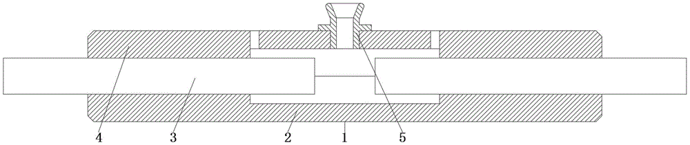
图1是本实用新型主视结构示意图。FIG. 1 is a schematic view of the front structure of the present utility model.
图2是本实用新型俯视结构示意图。FIG. 2 is a schematic top view of the structure of the present invention.
图3是本实用新型左视结构示意图。FIG. 3 is a schematic diagram of the left side view of the present utility model.
图4是本实用新型凹槽模具板俯视图。Figure 4 is a top view of the groove die plate of the present invention.
图中:1、装置本体;2、凹槽模具板;3、输电电缆芯;4、凸块模具板;5、可拆浇筑筒;6、对接固定块;7、便携开模柄。In the figure: 1. Device body; 2. Groove mold plate; 3. Power transmission cable core; 4. Bump mold plate; 5. Removable pouring cylinder;
具体实施方式Detailed ways
下面结合附图和实施例对本发明的实施方式作进一步详细描述。以下实施例用于说明本发明,但不能用来限制本发明的范围。The embodiments of the present invention will be described in further detail below with reference to the accompanying drawings and examples. The following examples are intended to illustrate the present invention, but not to limit the scope of the present invention.
在本发明的描述中,除非另有说明,“多个”的含义是两个或两个以上;术语“上”、“下”、“左”、“右”、“内”、“外”、“前端”、“后端”、“头部”、“尾部”等指示的方位或位置关系为基于附图所示的方位或位置关系,仅是为了便于描述本发明和简化描述,而不是指示或暗示所指的装置或元件必须具有特定的方位、以特定的方位构造和操作,因此不能理解为对本发明的限制。此外,术语“第一”、“第二”、“第三”等仅用于描述目的,而不能理解为指示或暗示相对重要性。In the description of the present invention, unless otherwise stated, "plurality" means two or more; the terms "upper", "lower", "left", "right", "inner", "outer" The orientation or positional relationship indicated by , "front end", "rear end", "head", "tail", etc. are based on the orientation or positional relationship shown in the accompanying drawings, and are only for the convenience of describing the present invention and simplifying the description, not An indication or implication that the referred device or element must have a particular orientation, be constructed and operate in a particular orientation, is not to be construed as a limitation of the invention. Furthermore, the terms "first," "second," "third," etc. are used for descriptive purposes only and should not be construed to indicate or imply relative importance.
在本发明的描述中,需要说明的是,除非另有明确的规定和限定,术语“相连”、“连接”应做广义理解,例如,可以是固定连接,也可以是可拆卸连接,或一体地连接;可以是机械连接,也可以是电连接;可以是直接相连,也可以通过中间媒介间接相连。对于本领域的普通技术人员而言,可以具体情况理解上述术语在本发明中的具体含义。In the description of the present invention, it should be noted that, unless otherwise expressly specified and limited, the terms "connected" and "connected" should be understood in a broad sense, for example, it may be a fixed connection, a detachable connection, or an integral connection. Ground connection; it can be a mechanical connection or an electrical connection; it can be directly connected or indirectly connected through an intermediate medium. For those of ordinary skill in the art, the specific meanings of the above terms in the present invention can be understood in specific situations.
实施例:Example:
如附图1至附图4所示:As shown in accompanying drawings 1 to 4:
本实用新型提供一种用于输电电缆中间接头的模塑式快速熔接装置,包括装置本体1,装置本体1底部设置有左右方向的凹槽模具板2,且凹槽模具板 2顶部对接安装有左右方向的凸块模具板4;凸块模具板4和凹槽模具板2之间左右端面中心均插入安装有左右方向的输电电缆芯3,且凸块模具板4和凹槽模具板2之间前后均插入安装有左右方向的对接固定块6,对接固定块6前后端面中间均开设有左右方向的限位槽,方便插入安装在凹槽模具板2和凸块模具板4 之间进行对接固定;凸块模具板4和凹槽模具板2前后端面中间均通过螺栓固定安装有左右方向的便携开模柄7,且凸块模具板4顶部中间固定安装有上下方向的可拆浇筑筒5,可拆浇筑筒5顶部端部设置有上下方向的喇叭口,且可拆浇筑筒5中间外部圆周设置有正六边形环板,可拆浇筑筒5底部外部圆周开设有安装螺纹,方便进行浇筑,方便自身通过工具进行安装和限位,方便通过螺纹安装在凸块模具板4顶部。The utility model provides a molding-type quick welding device for an intermediate joint of a power transmission cable, comprising a device body 1, the bottom of the device body 1 is provided with a
其中,凹槽模具板2顶部端面前后均开设有左右方向的凸形限位槽,且凹槽模具板2顶部端面中间前后均开设有左右方向的插入对接槽,凹槽模具板2 顶部端面中间左右两侧均开设有左右方向的半圆芯线槽,凹槽模具板2顶部端面中间开设有左右方向的浇筑半圆槽,方便对接固定块6限位安装,方便凸块模具板4插入限位对接,方便输电电缆芯3放入限位,方便浇筑液体进入凝固连接输电电缆芯3。Among them, the front and rear of the top end of the
其中,凸块模具板4底部端面前后均开设有左右方向的凸形限位槽,且凸块模具板4底部端面中间前后均开设有左右方向的插入对接块,凸块模具板4 底部端面中间左右两侧均开设有左右方向的半圆芯线槽,凸块模具板4底部端面中间开设有左右方向的浇筑半圆槽,凸块模具板4顶部中间开设有上下贯穿的螺纹孔,凸块模具板4顶部中间左右两侧均开设有上下贯穿的出气孔,方便对接固定块6限位安装,方便插入凹槽模具板2对接限位,方便输电电缆芯3 放入限位,方便浇筑液体进入凝固连接输电电缆芯3,方便可拆浇筑筒5通过螺纹固定安装,方便浇筑处内部空气排出和观察浇筑液体量。Among them, the front and rear of the bottom end of the
本实施例的具体使用方式与作用:The specific usage mode and function of this embodiment:
本实用新型中,使用时将凹槽模具板2取出放置在地面使凹槽朝上,将输电电缆芯3分别放入左右两侧,将凸块模具板4放置在凹槽模具板2顶部对接,将对接固定块6插入凹槽模具板2和凸块模具板4之间进行对接固定,注意事先将可拆浇筑筒5通过工具安装在凸块模具板4顶部中间,将浇筑的液体对准可拆浇筑筒5顶部开口倒入,通过凸块模具板4左右两侧出气孔观察,浇筑液体进入凸块模具板4出气孔后停止倒入,等待冷却,冷却后将对接固定块6通过工具顶出,将凸块模具板4通过便携开模柄7向上抬起取下,将连接好的输电电缆芯3从凹槽模具板2上取下,然后对浇筑连接处进行打磨即可;其中凸块模具板4方便放置在凹槽模具板2顶部对接并通过插入前后对接固定块6进行对接固定,方便可拆浇筑筒5通过螺纹固定安装和拆卸更换,方便浇注时通过顶部左右两侧出气孔进行排气,解决了单孔注入不方便排出内部空气容易存在气泡影响使用的问题;其中凹槽模具板2方便凸块模具板4放置在顶部对接并通过对接固定块6固定,方便输电电缆芯3之间浇筑冷却后快速脱模取下,方便通过便携开模柄7携带移动至需要使用的位置。In the utility model, when in use, the
本发明的实施例是为了示例和描述起见而给出的,而并不是无遗漏的或者将本发明限于所公开的形式。很多修改和变化对于本领域的普通技术人员而言是显而易见的。选择和描述实施例是为了更好说明本发明的原理和实际应用,并且使本领域的普通技术人员能够理解本发明从而设计适于特定用途的带有各种修改的各种实施例。The embodiments of the present invention are presented for purposes of illustration and description, and are not intended to be exhaustive or to limit the invention to the form disclosed. Many modifications and variations will be apparent to those of ordinary skill in the art. The embodiment was chosen and described in order to better explain the principles of the invention and the practical application, and to enable others of ordinary skill in the art to understand the invention for various embodiments with various modifications as are suited to the particular use.
Claims (5)
Priority Applications (1)
| Application Number | Priority Date | Filing Date | Title |
|---|---|---|---|
| CN202020986501.2U CN212063291U (en) | 2020-06-03 | 2020-06-03 | A quick welding set of moulding formula for transmission cable intermediate head |
Applications Claiming Priority (1)
| Application Number | Priority Date | Filing Date | Title |
|---|---|---|---|
| CN202020986501.2U CN212063291U (en) | 2020-06-03 | 2020-06-03 | A quick welding set of moulding formula for transmission cable intermediate head |
Publications (1)
| Publication Number | Publication Date |
|---|---|
| CN212063291U true CN212063291U (en) | 2020-12-01 |
Family
ID=73521000
Family Applications (1)
| Application Number | Title | Priority Date | Filing Date |
|---|---|---|---|
| CN202020986501.2U Active CN212063291U (en) | 2020-06-03 | 2020-06-03 | A quick welding set of moulding formula for transmission cable intermediate head |
Country Status (1)
| Country | Link |
|---|---|
| CN (1) | CN212063291U (en) |
-
2020
- 2020-06-03 CN CN202020986501.2U patent/CN212063291U/en active Active
Similar Documents
| Publication | Publication Date | Title |
|---|---|---|
| CN201601444U (en) | Joint box for casting bus duct | |
| CN203472083U (en) | Mold for injection molding part | |
| CN202230867U (en) | Dry type phase-shifting rectifier transformer coil casting mold | |
| CN210436522U (en) | Injection mold | |
| CN108607971A (en) | It is used to prepare the sand core, mold and die casting equipment of the electric machine casing of new-energy automobile | |
| CN107953494A (en) | A kind of water-proof connector perfusion epoxy AB glue molding structure and pouring and molding method | |
| CN105697885B (en) | Conduit fixing device, prefabricated component mold, prefabricated component and installing structure | |
| CN209579941U (en) | A kind of tile mould preventing knockout course raw material adhesion | |
| CN204525981U (en) | Novel easy glue-injection frock | |
| CN215941473U (en) | General type cast joint mould | |
| CN202731935U (en) | Tunnel lining trolley reserved groove | |
| CN211974344U (en) | Wall body water and electricity wire casing pre-buried mould | |
| CN208099259U (en) | A kind of fast mold exchange | |
| CN211194613U (en) | Moulding mould of using of encapsulation casing | |
| CN220943187U (en) | A demoulding device for powder pressed rubber sleeve | |
| CN209937632U (en) | Extrusion molding mold core and mold for electric wire and cable | |
| CN202934728U (en) | Double-head centralized water supply device | |
| CN217257686U (en) | A core rod structure of a mold | |
| CN218083887U (en) | A non-partitioned plug injection mold | |
| CN222245898U (en) | A six outer corner joint fixed plate structures for injection mold installation | |
| CN221087236U (en) | Casting mold of bearing chamber | |
| CN217597699U (en) | Receiver lower cover plastic forming die | |
| CN221912560U (en) | A mold for producing cement electric poles | |
| CN218342436U (en) | Concrete pouring equipment | |
| CN215803255U (en) | Pull rod assembly |
Legal Events
| Date | Code | Title | Description |
|---|---|---|---|
| GR01 | Patent grant | ||
| GR01 | Patent grant | ||
| TR01 | Transfer of patent right | ||
| TR01 | Transfer of patent right |
Effective date of registration: 20260427 Address after: 214200 industrial concentration zone, Gaocheng Town, Yixing City, Wuxi City, Jiangsu Province Patentee after: JIANGSU AONENG ELECTRICITY CABLE ACCESSORIES Co.,Ltd. Country or region after: China Address before: 214200 Jiangsu Province Wuxi City Yixing City Yicheng Street 886 Jiefang East Road Room 3902-1 Patentee before: Jiangsu miaoheng Technology Co.,Ltd. Country or region before: China |