CN212046166U - Bag handle connecting mechanism of paper bag machine - Google Patents
Bag handle connecting mechanism of paper bag machine Download PDFInfo
- Publication number
- CN212046166U CN212046166U CN202020108258.4U CN202020108258U CN212046166U CN 212046166 U CN212046166 U CN 212046166U CN 202020108258 U CN202020108258 U CN 202020108258U CN 212046166 U CN212046166 U CN 212046166U
- Authority
- CN
- China
- Prior art keywords
- paper
- bag
- bag handle
- connection mechanism
- machine according
- Prior art date
- Legal status (The legal status is an assumption and is not a legal conclusion. Google has not performed a legal analysis and makes no representation as to the accuracy of the status listed.)
- Active
Links
Images



Landscapes
- Making Paper Articles (AREA)
Abstract
本实用新型公开了纸袋机的袋把连接机构,包括上胶装置、纸带复合装置和袋把弯折装置,其特征在于:所述上胶装置包括储胶盒(10)、上胶条(8),所述上胶条(8)与第一驱动组件连接后可左右上下移动,在所述储胶盒(10)的一侧设置有纸带放卷组件和纸带切断组件,在所述纸带切断组件的出料端设置有料槽(15),对应所述料槽(15)的下方设置有所述的纸带复合装置和袋把弯折装置。本实用新型结构简单、设计合理,能够自动化地实现纸袋袋把的胶粘连接作业。

The utility model discloses a bag handle connection mechanism of a paper bag machine, which comprises a gluing device, a paper tape compounding device and a bag handle bending device. The utility model is characterized in that: the gluing device comprises a glue storage box (10), a glue strip ( 8), the glue strip (8) can move left and right up and down after being connected with the first drive assembly, and a tape unwinding assembly and a tape cutting assembly are arranged on one side of the glue storage box (10). A material chute (15) is provided at the discharge end of the paper tape cutting assembly, and the paper tape compounding device and the bag handle bending device are provided corresponding to the lower part of the material chute (15). The utility model has the advantages of simple structure and reasonable design, and can automatically realize the glue connection operation of the handle of the paper bag.
Description
技术领域technical field
本实用新型涉及包装领域,具体涉及一种纸袋机的袋把连接机构。The utility model relates to the field of packaging, in particular to a bag handle connecting mechanism of a paper bag machine.
背景技术Background technique
目前,市面上的大部分纸袋都带有袋把,以便人们提拿纸袋。纸袋在生产过程中,往往会先将袋把焊接在纸袋的基材上,而针对纸质材料纸袋和袋把,焊接并不是最好的连接方式,导致其连接的效果较差,因此,市面上有些纸袋和袋把之间是通过胶粘的方式进行连接的,而胶粘连接一般都是通过人工操作完成的,生产效率和质量较低、工人劳动强度大,而市面上的胶粘连接装置结构普遍比较复杂,而且胶粘连接的效果也较差。At present, most of the paper bags on the market have a handle for people to carry the paper bag. In the production process of paper bags, the bag handle is often welded to the base material of the paper bag first. For paper bags and bag handles, welding is not the best connection method, resulting in poor connection effect. Therefore, the market Some paper bags and the bag handle are connected by gluing, and the gluing connection is generally completed by manual operation, the production efficiency and quality are low, and the labor intensity of workers is high. The structure of the device is generally complicated, and the effect of the adhesive connection is also poor.
实用新型内容Utility model content
鉴于背景技术的不足,本实用新型所要解决的技术问题是提供一种能够自动化地实现纸袋袋把的胶粘连接作业的纸袋机的袋把连接机构。In view of the deficiencies of the background technology, the technical problem to be solved by the present invention is to provide a bag handle connection mechanism of a paper bag machine that can automatically realize the glue connection operation of the paper bag bag handle.
为此,本实用新型是采用如下方案来实现的:For this reason, the utility model adopts the following scheme to realize:
纸袋机的袋把连接机构,包括上胶装置、纸带复合装置和袋把弯折装置,其特征在于:所述上胶装置包括储胶盒、上胶条,所述上胶条与第一驱动组件连接后可左右上下移动,在所述储胶盒的一侧设置有纸带放卷组件和纸带切断组件,在所述纸带切断组件的出料端设置有料槽,对应所述料槽的下方设置有所述的纸带复合装置和袋把弯折装置。The bag handle connection mechanism of the paper bag machine includes a gluing device, a paper tape compound device and a bag handle bending device. After the drive assembly is connected, it can move left and right up and down. A tape unwinding assembly and a tape cutting assembly are arranged on one side of the plastic storage box. The paper tape compounding device and the bag handle bending device are arranged below the groove.
所述储胶盒的上开口处转动设置有胶辊。A rubber roller is rotatably arranged at the upper opening of the plastic storage box.
所述第一驱动组件包括第一驱动电机和传动臂,所述第一驱动电机与第一传动轮传动连接,所述第一传动轮通过第一传动带与第二传动轮连接,所述传动臂偏心地与所述第一传动轮和第二传动轮铰接,所述上胶条连接在所述传动臂上。The first drive assembly includes a first drive motor and a transmission arm, the first drive motor is drivingly connected with a first transmission wheel, the first transmission wheel is connected with a second transmission wheel through a first transmission belt, and the transmission arm It is eccentrically hinged with the first transmission wheel and the second transmission wheel, and the glue strip is connected to the transmission arm.
所述纸带切断组件包括切断刀、与切断刀配合的刀座和驱动气缸,所述切断刀的一端铰接在机架上,所述驱动气缸的活塞杆与所述切断刀铰接。The paper tape cutting assembly includes a cutting knife, a knife seat matched with the cutting knife and a driving cylinder, one end of the cutting knife is hinged on the frame, and the piston rod of the driving cylinder is hinged with the cutting knife.
在所述料槽的左右两侧设置有挡板,所述挡板上设置有挡条。Baffles are arranged on the left and right sides of the material trough, and baffles are arranged on the baffles.
所述纸带复合装置包括吸盘、升降座、旋转轴以及与所述吸盘配合的压紧平台,所述旋转轴可转动地设置在升降座上,且其两端可转动的置于限位槽中,所述吸盘连接在所述旋转轴上,所述升降座与升降驱动组件连接。The paper tape compounding device includes a suction cup, a lifting seat, a rotating shaft and a pressing platform matched with the suction cup. The rotating shaft is rotatably arranged on the lifting seat, and both ends of the rotating shaft are rotatably placed in the limiting grooves. wherein, the suction cup is connected to the rotating shaft, and the lift seat is connected to the lift drive assembly.
所述升降驱动组件包括第二驱动电机,所述第二驱动电机与第三传动轮传动连接,所述第三传动轮与第二传动带连接,所述第二传动带与升降座连接。The lift drive assembly includes a second drive motor, the second drive motor is drivingly connected with a third transmission wheel, the third transmission wheel is connected with a second transmission belt, and the second transmission belt is connected with the lifting seat.
所述限位槽为“S”形。The limiting groove is "S" shaped.
所述旋转轴连接有弹性板,所述弹性板上设置有供所述吸盘穿出的让位槽。The rotating shaft is connected with an elastic plate, and the elastic plate is provided with a vacant slot for the suction cup to pass through.
所述袋把弯折装置包括左右间隔设置的压紧块,所述压紧块与升降动力组件连接,在所述压紧块的下方设置有转动体,所述转动体与转动动力组件连接。The bag handle bending device includes pressing blocks arranged at intervals on the left and right, the pressing blocks are connected with the lifting power component, and a rotating body is arranged below the pressing block, and the rotating body is connected with the rotating power component.
采用上述技术方案,本实用新型的优点为:结构简单,设计合理,能够自动化地实现纸袋基材以及袋把的上胶作业,同时在上胶完成后将纸带粘贴在纸袋基材上对袋把的粘接部位进行覆盖,进而保证袋把粘接稳定性和可靠性。By adopting the above technical scheme, the utility model has the advantages of simple structure and reasonable design, which can automatically realize the gluing operation of the paper bag base material and the bag handle, and at the same time, after the gluing is completed, the paper tape is pasted on the paper bag base material and the bag Cover the bonding part of the bag to ensure the bonding stability and reliability of the bag.
附图说明Description of drawings
本实用新型有如下附图:The utility model has the following accompanying drawings:
图1为本实用新型的结构图;Fig. 1 is the structural drawing of the utility model;
图2为图1中A指向处的局部放大图;Fig. 2 is a partial enlarged view of the point where A points in Fig. 1;
图3为图1中B指向处的局部放大图;Fig. 3 is a partial enlarged view of the point where B points in Fig. 1;
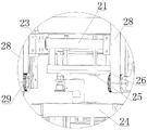
图4 为本实用新型纸带复合装置处的视图;4 is a view of the paper tape compounding device of the present invention;
图5为图4中C指向处的局部放大图;Fig. 5 is a partial enlarged view of the place where C points in Fig. 4;
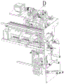
图6为图4另一视角的视图;FIG. 6 is a view from another perspective of FIG. 4;
图7为图6中D指向处的局部放大图;Fig. 7 is a partial enlarged view of the place where D points in Fig. 6;
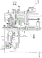
图8为图6另一视角的视图;FIG. 8 is a view from another perspective of FIG. 6;
图9为图8中E指向处的局部放大图;Fig. 9 is a partial enlarged view of the point where E points in Fig. 8;
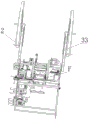
图10为本实用新型纸带复合装置处另一视角的视图;10 is a view from another perspective at the paper tape composite device of the present invention;
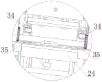
图11为图10中F指向处的局部放大图。FIG. 11 is a partial enlarged view of the point where F points in FIG. 10 .
具体实施方式Detailed ways
1、如图所示,本实用新型公开的纸袋机的袋把连接机构,包括上胶装置、纸带复合装置和袋把弯折装置,上胶装置包括储胶盒10、上胶条8以及与之配合的上胶平台7,上胶条8与第一驱动组件连接后可左右上下移动,本实施例中,第一驱动组件包括第一驱动电机1和传动臂11,第一驱动电机1与第一传动轮3传动连接,第一传动轮3通过第一传动带4与第二传动轮5连接,传动臂11偏心地与第一传动轮3和第二传动轮5铰接,上胶条8连接在传动臂11上。在储胶盒10的上开口处转动设置有胶辊9。第二传动轮5与第四传动轮6传动连接,第四传动轮6与胶辊9连接,随着第一驱动电机1动作,可以带动第一、第二传动轮转动,同时带动传动臂11以及上胶条8先移动至胶辊9处蘸取一定的胶水,之后再移动至上胶平台7处,此时纸袋基材已经被运送至上交平台7上,纸袋基材的运送机构属于现有技术,且不是本申请的创新点,故不再进行赘述,之后上胶条8将胶水涂抹在纸袋基材的袋把粘接处。在上胶平台7的一侧设置有纸带放卷组件和纸带切断组件,纸带放卷组件包括放卷座2,成卷的纸带放置在放卷座2上进行放卷,纸带切断组件包括切断刀13、与切断刀13配合的刀座31和驱动气缸12,切断刀13的一端铰接在机架14上,驱动气缸12的活塞杆与切断刀13铰接。通过控制驱动气缸12即可带动切断刀13进行摆动并于刀座31配合,进而实现纸带的切断,在纸带切断组件的出料端设置有料槽15,对应料槽15的下方设置有的纸带复合装置和袋把弯折装置。在料槽15的左右两侧设置有挡板16,防止纸带发生偏移,挡板16上设置有挡条32,将切断的纸带托住,避免纸带直接从料槽15落下,等待纸带复合装置吸取该纸带。具体的,纸带复合装置包括吸盘25、升降座23、旋转轴21以及与吸盘25配合的压紧平台24,旋转轴21可转动地设置在升降座23上,且其两端可转动的置于限位槽20中,限位槽20呈“S”形,限位槽20设置在导向板18上,具体的,旋转轴21的两端连接有导向块22,导向块22上偏心地设置有导向轴30,导向轴30穿设在限位槽20内导向轴30上连接有轴承19,使得其在限位槽20内更顺滑地进行移动,当升降座23带着旋转轴21进行升降时,导向块22在限位槽20的带动下进行转动,进而带动旋转轴21以及吸盘25进行上下翻转。吸盘25连接在旋转轴21上,升降座23与升降驱动组件连接,具体的,升降驱动组件包括第二驱动电机17,第二驱动电机17与第三传动轮29传动连接,第三传动轮29与第二传动带28连接,第二传动带28与升降座23连接,通过控制第二驱动电机17带动第二传动带28移动,即可带动升降座23和吸盘25进行升降,当然,除了上述结构外,升降座23还可以与气缸、直线电机、滚珠丝杆等常见的驱动组件连接实现其升降。旋转轴21连接有弹性板26,弹性板26上设置有供吸盘25穿出的让位槽。确保弹性板26能够完整地对纸带进行挤压,进而将纸带压实在纸袋基材上,并对袋把的粘胶部位进行粘连和覆盖。袋把弯折装置包括左右间隔设置的压紧块34,所述压紧块34与升降动力组件连接,升降动力组件可以是气缸、油缸等,在压紧块34的下方设置有转动体35,转动体35与转动动力组件连接,转动动力组件可以是常规的电机。1. As shown in the figure, the bag handle connection mechanism of the paper bag machine disclosed by the present utility model includes a gluing device, a paper tape compound device and a bag handle bending device. The gluing device includes a
本实用新型的这种结构,当纸袋基材和袋把被送至上胶平台7处时,第一驱动电机1带动传动臂11移动,带动上胶条8先移动至胶辊9处蘸取一定的胶水,之后再移动至上胶平台7处,将胶水蘸在纸袋基材的袋把粘接处,之后随着纸袋基材的运送,纸袋基材被送至压紧平台24处,而纸带在纸带放卷组件的带动下移动至切断刀13处被切断,此时第二驱动电机17动作,带动升降座23上升,同时限位槽20带动旋转轴21朝上转动,带动吸盘25朝上翻转并从料槽15处吸取已经切断的纸带,紧接着第二驱动电机17反转,带动升降座23下降,同时限位槽20带动旋转轴21朝下转动,带动吸盘25朝下翻转,最后吸盘25移动至压紧平台24处的纸袋基材处,此时,成卷的袋把随着袋把放卷架33进行放卷,并通过切断机构切断,并在运送机构的带动下被送至靠近压紧平台24处,此时袋把弯折装置中的压紧块34下降,将切断的袋把紧压在压紧块34和转动体35之间,接着转动体35旋转,袋把发生弯折,且袋把的两端刚好伸入到压紧平台24处并位于纸袋基材的上方,其中袋把的放卷、切断和运送机构与无纺布烫把机的结构相同,属于现有技术,且与本申请的创新点无关,故不再进行赘述,之后吸盘25松开纸带,使得纸带下落到纸袋基材的粘胶处并覆盖住袋把的两端,最后升降座23再下降一定距离,使得弹性板26能够完整地将纸带压紧在纸袋基材以及袋把的粘胶处,并对纸袋袋把进行覆盖,将纸带粘牢。With this structure of the present invention, when the paper bag base material and the bag handle are sent to the
本实用新型结构简单,设计合理,能够自动化地实现纸袋基材以及袋把的上胶作业,同时在上胶完成后将纸带粘贴在纸袋基材上对袋把的粘接部位进行覆盖,进而保证袋把粘接稳定性和可靠性。The utility model has the advantages of simple structure and reasonable design, and can automatically realize the gluing operation of the paper bag base material and the bag handle. Guarantee the bag handle bonding stability and reliability.
Claims (10)
Priority Applications (1)
| Application Number | Priority Date | Filing Date | Title |
|---|---|---|---|
| CN202020108258.4U CN212046166U (en) | 2020-01-17 | 2020-01-17 | Bag handle connecting mechanism of paper bag machine |
Applications Claiming Priority (1)
| Application Number | Priority Date | Filing Date | Title |
|---|---|---|---|
| CN202020108258.4U CN212046166U (en) | 2020-01-17 | 2020-01-17 | Bag handle connecting mechanism of paper bag machine |
Publications (1)
| Publication Number | Publication Date |
|---|---|
| CN212046166U true CN212046166U (en) | 2020-12-01 |
Family
ID=73538781
Family Applications (1)
| Application Number | Title | Priority Date | Filing Date |
|---|---|---|---|
| CN202020108258.4U Active CN212046166U (en) | 2020-01-17 | 2020-01-17 | Bag handle connecting mechanism of paper bag machine |
Country Status (1)
| Country | Link |
|---|---|
| CN (1) | CN212046166U (en) |
Cited By (2)
| Publication number | Priority date | Publication date | Assignee | Title |
|---|---|---|---|---|
| CN111037999A (en) * | 2020-01-17 | 2020-04-21 | 浙江欧诺机械有限公司 | Bag handle connecting mechanism of paper bag machine |
| CN113968046A (en) * | 2021-11-19 | 2022-01-25 | 上豪包装机械(镇江)有限公司 | Conveying device with flat rope handle on the outside of paper bag |
-
2020
- 2020-01-17 CN CN202020108258.4U patent/CN212046166U/en active Active
Cited By (3)
| Publication number | Priority date | Publication date | Assignee | Title |
|---|---|---|---|---|
| CN111037999A (en) * | 2020-01-17 | 2020-04-21 | 浙江欧诺机械有限公司 | Bag handle connecting mechanism of paper bag machine |
| CN111037999B (en) * | 2020-01-17 | 2025-05-23 | 浙江欧诺机械科技股份有限公司 | Bag handle connection mechanism of paper bag machine |
| CN113968046A (en) * | 2021-11-19 | 2022-01-25 | 上豪包装机械(镇江)有限公司 | Conveying device with flat rope handle on the outside of paper bag |
Similar Documents
| Publication | Publication Date | Title |
|---|---|---|
| CN111037999A (en) | Bag handle connecting mechanism of paper bag machine | |
| CN111846488A (en) | Blade type bag breaking machine | |
| CN114516437A (en) | Foam production is with collecting packaging production line certainly | |
| CN221418922U (en) | A paper roll slitting and bundling device | |
| CN111908236A (en) | Express delivery refuse collection treatment facility | |
| CN111924158A (en) | Automatic packaging device for packaging box | |
| CN112373124B (en) | Wrapping bag processing equipment | |
| CN216832524U (en) | Automatic gluing mechanism for panel paper of cake box bottom support | |
| CN214326644U (en) | Automatic blanking device for PE film winding | |
| CN214325570U (en) | Cavity glass inlayer sticky tape banding device | |
| CN211888468U (en) | Automatic feeding and waste discharging slicing mechanism for punching machine | |
| CN219686718U (en) | Cutting equipment is used in production of PE bag that stability is good | |
| CN211682652U (en) | A rubberizing seals device for office furniture sheet material banding equipment | |
| CN214325569U (en) | Edge sealing device for outer layer adhesive tape of hollow glass | |
| CN109671968B (en) | Film coating device and film coating method thereof | |
| CN219171813U (en) | Carry and cut off interlude paper handle mechanism | |
| CN220298827U (en) | Gland rubberizing device for blister box packaging | |
| CN210755474U (en) | Edge folding machine with material guide device | |
| CN221249083U (en) | Corrugated board processing die cutting machine convenient for waste collection | |
| CN210306032U (en) | Building new material cutting material feeding unit | |
| CN223875409U (en) | Paper diaper water absorbing paper glue spraying device | |
| CN214212473U (en) | Cutter unloader of grid tray allies oneself with piece processing equipment | |
| CN221369864U (en) | Double-channel double-sided adhesive tape pasting machine | |
| CN219191501U (en) | Paper tape handle processing production line | |
| CN219408541U (en) | Automatic tape connecting mechanism |
Legal Events
| Date | Code | Title | Description |
|---|---|---|---|
| GR01 | Patent grant | ||
| GR01 | Patent grant | ||
| CP03 | Change of name, title or address |
Address after: 325400 f-02-3 area of Xinxing Industrial Park in Pingyang County, Wenzhou City, Zhejiang Province Patentee after: Zhejiang Ounuo Machinery Technology Co.,Ltd. Country or region after: China Address before: 325400 f-02-3 area of Xinxing Industrial Park in Pingyang County, Wenzhou City, Zhejiang Province Patentee before: Zhejiang Ono Machinery Co.,Ltd. Country or region before: China |
|
| CP03 | Change of name, title or address |