CN212031525U - Anti-blocking through-flow type dynamic pressure velocity measurement system for dusty airflow - Google Patents
Anti-blocking through-flow type dynamic pressure velocity measurement system for dusty airflow Download PDFInfo
- Publication number
- CN212031525U CN212031525U CN202020189172.9U CN202020189172U CN212031525U CN 212031525 U CN212031525 U CN 212031525U CN 202020189172 U CN202020189172 U CN 202020189172U CN 212031525 U CN212031525 U CN 212031525U
- Authority
- CN
- China
- Prior art keywords
- pipeline
- pressure measurement
- static pressure
- flowmeter
- static
- Prior art date
- Legal status (The legal status is an assumption and is not a legal conclusion. Google has not performed a legal analysis and makes no representation as to the accuracy of the status listed.)
- Active
Links
- 238000005259 measurement Methods 0.000 title claims abstract description 23
- 238000009530 blood pressure measurement Methods 0.000 claims abstract description 39
- 230000003068 static effect Effects 0.000 claims abstract description 37
- 239000012530 fluid Substances 0.000 abstract description 4
- 238000012360 testing method Methods 0.000 abstract description 4
- 238000003466 welding Methods 0.000 abstract description 3
- 239000000428 dust Substances 0.000 description 3
- 238000000034 method Methods 0.000 description 3
- 239000000843 powder Substances 0.000 description 3
- 238000010298 pulverizing process Methods 0.000 description 3
- 239000003245 coal Substances 0.000 description 2
- 238000011144 upstream manufacturing Methods 0.000 description 2
- 230000004075 alteration Effects 0.000 description 1
- 238000010586 diagram Methods 0.000 description 1
- 230000000694 effects Effects 0.000 description 1
- 238000012986 modification Methods 0.000 description 1
- 230000004048 modification Effects 0.000 description 1
- 238000002360 preparation method Methods 0.000 description 1
Images
Landscapes
- Measuring Volume Flow (AREA)
Abstract
The utility model discloses a dusty air current prevents blockking up through-flow formula dynamic pressure system of testing speed belongs to fluid velocity measurement field. At present, no measuring device capable of meeting the requirement of long-time continuous measurement exists for dusty gas flow. The utility model discloses a small-size fan, a flowmeter, No. two flowmeters, static pressure measurement pipeline and total pressure measurement pipeline, small-size fan is connected with a flowmeter and No. two flowmeters respectively through a hose and No. two hoses, a flowmeter is connected with static pressure measurement pipeline through No. four hoses, No. two flowmeters are connected with total pressure measurement pipeline through No. three hoses, static pressure measurement interface has been seted up on the static pressure measurement pipeline, total pressure measurement interface has been seted up on the pipeline, total pressure measurement pipeline and static pressure measurement pipeline welding constitute standard back pipe together. The utility model discloses can thoroughly solve measuring device among the dusty airflow velocity measurement and block up the problem.
Description
Technical Field
The utility model relates to a dusty air current prevents blockking up through-flow formula dynamic pressure system of testing speed belongs to fluid velocity measurement field.
Background
The coal-fired power plant boiler is basically a pulverized coal boiler, the pulverizing system is an important auxiliary device of the boiler, and the safety and the economy of the boiler operation are closely related to the operating parameters of the pulverizing system. An important parameter for evaluating the powder preparation system is whether the wind speed value in the pulverized coal pipe is within a reasonable range and whether the wind speed deviation of the same-layer powder pipe is reasonable. The measurement of the wind speed of a pulverizing system is the most common measurement of the dust-containing gas flow speed of a utility boiler.
At present, the wind speed measuring equipment commonly used by national standard regulations comprises an S-shaped backrest pipe and a pitot pipe, and the two types of equipment can effectively measure under the condition of pure air. These two types of devices are still used in the measurement of the flow rate of the dusty gas stream, but in the case of a high dust concentration, the measurement cannot be continued for a long time because of easy clogging; in addition, even if the data is not completely blocked, the data fluctuation range is large in the measurement process, so that the data cannot be accurately read. Because the wind speed measurement standard in the pipe requires a grid method, the measurement time is long as more measurement points are positioned in the cross section, and the measurement cannot be completed continuously, the working intensity on site is increased, and the reliability of measurement data is reduced. At present, no measuring device capable of meeting the requirement of long-time continuous measurement exists for dusty gas flow.
For the above reasons, in order to effectively solve the problem of the blockage of the measuring device during the measurement of the dusty air flow, a new dynamic pressure speed measuring system for preventing the blockage needs to be developed.
SUMMERY OF THE UTILITY MODEL
The utility model aims to solve the problem that measuring device takes place the jam easily when the speed of dusty air current is measured, and provide a through-flow type dynamic pressure speed measuring system is prevented blockking up by dusty air current.
The utility model provides a technical scheme that above-mentioned problem adopted is: the utility model provides a dusty air current prevents blockking up STREAMING dynamic pressure system of testing speed, characterized by, includes small-size fan, a flowmeter, No. two flowmeters, static pressure measurement pipeline and total pressure measurement pipeline, small-size fan is connected with a flowmeter and No. two flowmeters respectively through a hose and No. two hoses, a flowmeter is connected with the static pressure measurement pipeline through No. four hoses, No. two flowmeters are connected with the total pressure measurement pipeline through No. three hoses, the static pressure measurement interface has been seted up on the static pressure measurement pipeline, the total pressure measurement pipeline has been seted up No. two static pressure measurement interfaces, the welding of total pressure measurement pipeline and static pressure measurement pipeline constitutes standard back pipe together.
Furthermore, when the measurement is carried out, air is introduced into the full-pressure measurement pipeline and the static-pressure measurement pipeline, so that the gun head part of the backrest pipe is not blocked even when the flow velocity of the airflow with powder is measured.
Furthermore, a small fan, a second hose, a second flowmeter, a third hose and a full-pressure measuring pipeline are sequentially arranged in the direction of a through-flow medium in the full-pressure measuring pipeline from upstream to downstream, and an exhaust outlet of the full-pressure measuring pipeline is positioned in the measured medium; a small fan, a first hose, a first flowmeter, a fourth hose and a static pressure measuring pipeline are sequentially arranged in the static pressure measuring pipeline from upstream to downstream in the through-flow medium direction, and an exhaust outlet of the static pressure measuring pipeline is positioned in the measured medium.
Furthermore, the flow rates of the medium flowing through the full-pressure measuring pipeline and the static pressure measuring pipeline are controlled to be smaller as much as possible under the condition that the backrest pipe is prevented from being blocked, and the flow rates in the full-pressure measuring pipeline and the static pressure measuring pipeline can be controlled to be the same value.
Preferably, the full-pressure measurement pipeline and the static-pressure measurement pipeline have the same structure, so that the fluid resistance characteristics are ensured to be the same (the resistance is the same under the same flow), and the measurement parameter relationship is as follows:


the right side of the above formula shows the resistance of the full-pressure measuring pipeline and the static-pressure measuring pipeline after through-flow, which can be obtained by a special calibration test for the equipment (the relationship between the pipeline resistance and the through-flow rate is obtained by calibration). The dynamic pressure Δ P ═ P, which is characteristic of the flow velocity of the medium to be measured, is therefore1-P2Can be passed through P3And P4Is determined.
Preferably, the full-pressure measuring pipeline and the static-pressure measuring pipeline are welded back to back, and the structure of the full-pressure measuring pipeline and the static-pressure measuring pipeline is strictly manufactured according to a standard S-shaped backrest pipe.
Furthermore, the flow rates of the medium flowing through the full-pressure measuring pipeline and the static-pressure measuring pipeline are kept to be smaller and equal (Q)1=Q2In this case), the flow-through medium generates the same line resistance on both sides, and the dynamic pressure Δ P, which is characteristic of the flow velocity of the medium to be measured, is equal to P1-P2=P3-P4。
Compared with the prior art, the utility model, have following advantage and effect: the utility model discloses in have flowing medium because of the system expert, can thoroughly solve the problem that measuring device blockked up when measuring the great dusty air current of dust concentration through this way.
Drawings
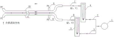
Fig. 1 is a schematic structural diagram of an embodiment of the present invention.
In the figure: the device comprises a small fan 1, a first hose 2, a second hose 3, a first flowmeter 4, a second flowmeter 5, a third hose 6, a fourth hose 7, a first static pressure measuring interface 8, a second static pressure measuring interface 9, a static pressure measuring pipeline 10 and a full pressure measuring pipeline 11.
Detailed Description
The present invention will be described in further detail by way of examples with reference to the accompanying drawings, which are illustrative of the present invention and are not intended to limit the present invention.
Referring to fig. 1, in this embodiment, a through-flow type dynamic pressure velocity measurement system is prevented blockking up by dusty air current, including small-size fan 1, a flowmeter 4, No. two flowmeters 5, static pressure measurement pipeline 10 and total pressure measurement pipeline 11, small-size fan 1 is connected with a flowmeter 4 and No. two flowmeters 5 respectively through a hose 2 and No. two hoses 3, a flowmeter 4 is connected with static pressure measurement pipeline 10 through No. four hoses 7, No. two flowmeters 5 are connected with total pressure measurement pipeline 11 through No. three hoses 6, static pressure measurement interface 8 has been seted up on static pressure measurement pipeline 10, total pressure measurement pipeline 11 has been seted up No. two static pressure measurement interface 9, total pressure measurement pipeline 11 and static pressure measurement pipeline 10 welding constitute standard back pipe together.
In this embodiment, the structures of the full-pressure measurement pipeline 11 and the static-pressure measurement pipeline 10 are completely the same, so that the fluid resistance characteristics are ensured to be the same (the resistance is the same under the same flow rate).
In this embodiment, the flow rates of the medium flowing through the full-pressure measuring line 11 and the static-pressure measuring line 10 are kept to be equal to each other (Q)1=Q2In this case), the flow-through medium generates the same line resistance on both sides, and the dynamic pressure Δ P, which is characteristic of the flow velocity of the medium to be measured, is equal to P1-P2=P3-P4。
The using method comprises the following steps: the full-pressure measuring pipeline 11 is just opposite to the measured medium, the small fan 1 runs, and the first flowmeter 4 and the second flowmeter 5 are adjusted to ensure that the flow velocity of the medium flowing through the full-pressure measuring pipeline 11 is equal to that of the medium flowing through the static pressure measuring pipeline 10 (V)1=V2) Keeping a small flow, and measuring the static pressure P by connecting a pressure gauge with a second static pressure measuring interface 9 on a full-pressure measuring pipeline 113A first static pressure measuring interface 8 connected with a static pressure measuring pipeline 10 by a pressure gauge is used for measuring the static pressure P4(ii) a Because of the control of the throughflow, the dynamic pressure Δ P ═ P characterizing the flow velocity of the medium to be measured1-P2=P3-P4The flow velocity of the measured medium can be further calculated through a relational formula of dynamic pressure and flow velocity.
Those not described in detail in this specification are well within the skill of the art.
Although the present invention has been described with reference to the above embodiments, it should not be construed as being limited to the scope of the present invention, and any modifications and alterations made by those skilled in the art without departing from the spirit and scope of the present invention should fall within the scope of the present invention.
Claims (2)
1. A dusty airflow anti-clogging through-flow type dynamic pressure speed measurement system is characterized by comprising a small fan (1), a first flowmeter (4), a second flowmeter (5), a static pressure measurement pipeline (10) and a full pressure measurement pipeline (11), the small fan (1) is respectively connected with the first flowmeter (4) and the second flowmeter (5) through the first hose (2) and the second hose (3), the first flowmeter (4) is connected with a static pressure measuring pipeline (10) through a fourth hose (7), the second flowmeter (5) is connected with a full pressure measuring pipeline (11) through a third hose (6), a first static pressure measuring interface (8) is arranged on the static pressure measuring pipeline (10), a second static pressure measuring interface (9) is arranged on the full pressure measuring pipeline (11), and the full-pressure measuring pipeline (11) and the static-pressure measuring pipeline (10) are welded together to form a backrest pipe.
2. The anti-clogging through-flow type dynamic pressure velocity measurement system for dusty gas flow according to claim 1, wherein the structure of the full pressure measurement pipeline (11) and the structure of the static pressure measurement pipeline (10) are completely the same.
Priority Applications (1)
| Application Number | Priority Date | Filing Date | Title |
|---|---|---|---|
| CN202020189172.9U CN212031525U (en) | 2020-02-20 | 2020-02-20 | Anti-blocking through-flow type dynamic pressure velocity measurement system for dusty airflow |
Applications Claiming Priority (1)
| Application Number | Priority Date | Filing Date | Title |
|---|---|---|---|
| CN202020189172.9U CN212031525U (en) | 2020-02-20 | 2020-02-20 | Anti-blocking through-flow type dynamic pressure velocity measurement system for dusty airflow |
Publications (1)
| Publication Number | Publication Date |
|---|---|
| CN212031525U true CN212031525U (en) | 2020-11-27 |
Family
ID=73491958
Family Applications (1)
| Application Number | Title | Priority Date | Filing Date |
|---|---|---|---|
| CN202020189172.9U Active CN212031525U (en) | 2020-02-20 | 2020-02-20 | Anti-blocking through-flow type dynamic pressure velocity measurement system for dusty airflow |
Country Status (1)
| Country | Link |
|---|---|
| CN (1) | CN212031525U (en) |
Cited By (1)
| Publication number | Priority date | Publication date | Assignee | Title |
|---|---|---|---|---|
| CN111289769A (en) * | 2020-02-20 | 2020-06-16 | 华电电力科学研究院有限公司 | Dust-laden airflow anti-blocking through-flow dynamic pressure velocity measuring system and its use method |
-
2020
- 2020-02-20 CN CN202020189172.9U patent/CN212031525U/en active Active
Cited By (1)
| Publication number | Priority date | Publication date | Assignee | Title |
|---|---|---|---|---|
| CN111289769A (en) * | 2020-02-20 | 2020-06-16 | 华电电力科学研究院有限公司 | Dust-laden airflow anti-blocking through-flow dynamic pressure velocity measuring system and its use method |
Similar Documents
| Publication | Publication Date | Title |
|---|---|---|
| CN103033289B (en) | Integrated measuring device for multiple-point type flow velocity pressure temperature | |
| CN108333004B (en) | A flue gas extraction system and flue gas extraction method applied to ammonia escape detection | |
| CN104729637A (en) | Turbine flowmeter online calibration system and method | |
| CN207231786U (en) | A kind of air-valve comprehensive performance test device | |
| CN115585872B (en) | A system for measuring and correcting air volume in a non-uniform wind field duct | |
| CN110715700B (en) | Flow regulator and metering device integrated device | |
| WO2024082763A1 (en) | Air volume measuring system for non-uniform wind field air ducts | |
| CN223756094U (en) | Air volume measurement system based on big data analysis | |
| CN115683240B (en) | A method for measuring air volume based on big data analysis | |
| CN103308106B (en) | High-pressure inert gas fire extinguishing agent mass flowmeter | |
| CN105865542A (en) | Integrated measuring device and method for smoke flow and pollutants | |
| WO2024082764A1 (en) | Air volume measurement and correction method for air duct of non-uniform air field | |
| US20170322059A1 (en) | Low pressure drop and high temperature flow measuring device | |
| CN107664523A (en) | A kind of full flue gas flow measurement apparatus of matrix form and method | |
| CN115683242B (en) | A wind volume measurement system for a rectangular duct with a non-uniform wind field | |
| CN219495322U (en) | Air quantity measuring system of non-uniform wind field air duct | |
| CN207964391U (en) | A kind of flue gas sampling device | |
| CN111289769A (en) | Dust-laden airflow anti-blocking through-flow dynamic pressure velocity measuring system and its use method | |
| CN214066654U (en) | Denitration flue gas sampling system | |
| CN207280521U (en) | A kind of full flue gas flow measuring device of matrix form | |
| CN112113799B (en) | A readable anti-clogging coal powder isokinetic sampling system with air extraction flow and working method | |
| CN110243557A (en) | Pipe detection system, boiler components and method for detecting pipeline | |
| CN216747788U (en) | System suitable for vertical rectangular flue gas velocity distribution measurement | |
| CN213632796U (en) | Readable formula of bleed flow prevents blockking up buggy constant speed sampling system | |
| CN110530684A (en) | A power plant boiler flue gas component sampling device, measurement system and method |
Legal Events
| Date | Code | Title | Description |
|---|---|---|---|
| GR01 | Patent grant | ||
| GR01 | Patent grant |