CN212008132U - A kind of strength test device for steel truss floor deck - Google Patents
A kind of strength test device for steel truss floor deck Download PDFInfo
- Publication number
- CN212008132U CN212008132U CN202020524324.6U CN202020524324U CN212008132U CN 212008132 U CN212008132 U CN 212008132U CN 202020524324 U CN202020524324 U CN 202020524324U CN 212008132 U CN212008132 U CN 212008132U
- Authority
- CN
- China
- Prior art keywords
- workbench
- truss floor
- column
- limit
- threaded
- Prior art date
- Legal status (The legal status is an assumption and is not a legal conclusion. Google has not performed a legal analysis and makes no representation as to the accuracy of the status listed.)
- Expired - Fee Related
Links
Images




Landscapes
- Investigating Strength Of Materials By Application Of Mechanical Stress (AREA)
Abstract
本实用新型涉及强度测试装置领域,且公开了一种钢筋桁架楼承板强度测试装置,包括工作台与固定设置在下端外表面的支撑座,所述工作台的上端外表面开设有配合口,所述配合口的内侧滑动安装有调节结构,所述工作台的上端外表面靠近配合口的后方设置有冲压机构。本实用新型所述的一种钢筋桁架楼承板强度测试装置,通过设置有调节结构、配合口与限位压件,可以防止板体发生滑动,提高测试精度,同时可以防止板体冲压时两侧翘起而降低了对待检测位置板体的冲压效果,因此提升测试效果,冲压部分易于更换,确保冲压效果。

The utility model relates to the field of strength testing devices, and discloses a strength testing device for a steel truss floor deck, which comprises a workbench and a support seat fixed on the outer surface of the lower end, and the outer surface of the upper end of the workbench is provided with a fitting opening. An adjustment structure is slidably installed on the inner side of the matching port, and a punching mechanism is provided on the outer surface of the upper end of the worktable close to the rear of the matching port. The strength testing device of the steel truss floor bearing plate of the utility model is provided with an adjusting structure, a matching port and a limit pressing piece, which can prevent the plate body from sliding, improve the test accuracy, and at the same time prevent the plate body from being doubled during punching. The side warping reduces the stamping effect of the plate body to be tested, thus improving the testing effect, and the stamping part is easy to replace to ensure the stamping effect.
Description
技术领域technical field
本实用新型涉及强度测试装置领域,具体为一种钢筋桁架楼承板强度测试装置。The utility model relates to the field of strength testing devices, in particular to a strength testing device for steel truss floor bearing plates.
背景技术Background technique
钢筋桁架楼承板即为相互交错的板体互相固定连接而成,在强度测试过程中,通过测试装置进行冲压测试,观察板体的变形情况,但在板体放置后,容易发生滑动,影响后续冲压效果,其次,冲压过程中,两侧处易翘起,从而整体弯折,不利于局部位置的冲压观察,还有,冲压部分易受到刮擦而损坏,而更换不便,为此,我们提出一种钢筋桁架楼承板强度测试装置。Reinforced truss floor slabs are made of staggered slabs that are fixed and connected to each other. During the strength test, a stamping test is performed through the testing device to observe the deformation of the slab. However, after the slab is placed, it is prone to sliding, which affects The follow-up stamping effect, secondly, during the stamping process, the two sides are easy to warp, so that the whole is bent, which is not conducive to the stamping observation of the local position. Also, the stamping part is easily damaged by scratches, and it is inconvenient to replace. For this reason, we A strength test device for steel truss floor deck is proposed.
实用新型内容Utility model content
(一)解决的技术问题(1) Technical problems solved
针对现有技术的不足,本实用新型提供了一种钢筋桁架楼承板强度测试装置,具备板体放置后不易滑动、冲压时板体两侧不易上翘、冲压部分结构可更换使用的优点。Aiming at the deficiencies of the prior art, the utility model provides a strength testing device for a steel truss floor deck, which has the advantages that the plate body is not easy to slide after being placed, the two sides of the plate body are not easily upturned during punching, and the punched part structure can be replaced.
(二)技术方案(2) Technical solutions
为实现上述具备板体放置后不易滑动、冲压时板体两侧不易上翘、冲压部分结构可更换使用的目的,本实用新型提供如下技术方案:一种钢筋桁架楼承板强度测试装置,包括工作台与固定设置在下端外表面的支撑座,所述工作台的上端外表面开设有配合口,所述配合口的内侧滑动安装有调节结构,所述工作台的上端外表面靠近配合口的后方设置有冲压机构,其中:In order to achieve the above-mentioned purpose that the plate body is not easy to slide after being placed, the two sides of the plate body are not easy to be upturned during punching, and the punching part structure can be replaced and used, the utility model provides the following technical scheme: a steel truss floor bearing plate strength test device, comprising: The worktable and the support seat fixedly arranged on the outer surface of the lower end, the outer surface of the upper end of the worktable is provided with a matching port, the inner side of the matching port is slidably installed with an adjustment structure, and the outer surface of the upper end of the worktable is close to the matching port. The rear is provided with a stamping mechanism, in which:
所述调节结构包括滑动设置在配合口内侧的活动条、活动设置在活动条一侧外表面且穿过工作台一侧外表面的螺纹杆,所述螺纹杆与工作台之间螺纹配合,所述活动条以及工作台的上端外表面靠近配合口的一侧处开设有限位螺孔,所述限位螺孔的内侧设置有限位压件。The adjusting structure includes a movable bar slidably arranged on the inner side of the mating port, and a threaded rod movably arranged on the outer surface of one side of the movable bar and passing through the outer surface of one side of the worktable, and the threaded rod is threadedly matched with the worktable, so the A limit screw hole is provided on the side of the upper outer surface of the movable bar and the working table close to the fitting port, and a limit pressure piece is arranged on the inner side of the limit screw hole.
优选的,所述限位螺孔设置为相互平行的两组,且每组限位螺孔均沿一条直线上分布,所述限位压件的数量为四个。Preferably, the limit screw holes are arranged in two groups that are parallel to each other, and each group of limit screw holes is distributed along a straight line, and the number of the limit pressure pieces is four.
优选的,所述限位压件包括螺纹配合插入限位螺孔内侧的螺纹柱活动套在螺纹柱外表面的压片、螺纹配合方式套在螺纹柱外表面的压紧螺母,所述压紧螺母位于压片的上方。Preferably, the limiting pressure piece includes a pressing piece that is threadedly fitted into the threaded column inside the limiting screw hole and is movably sleeved on the outer surface of the threaded column, and a compression nut that is sleeved on the outer surface of the threaded column in a threaded manner. The nut is located above the tab.
优选的,所述螺纹杆的一端活动贯穿活动条的一侧外表面,且螺纹杆的一端固定连接有限位盘,所述螺纹杆的外表面固定套有限位环,所述限位环以及限位盘分别活动贴合在活动条的两侧外表面,所述螺纹杆与活动条之间通过限位盘以及限位环活动连接。Preferably, one end of the threaded rod movably runs through the outer surface of one side of the movable bar, and one end of the threaded rod is fixedly connected to a limit plate, the outer surface of the threaded rod is fixedly sleeved with a limit ring, the limit ring and the limiter The position discs are respectively movably attached to the outer surfaces of the two sides of the movable bar, and the threaded rod and the movable bar are movably connected by a limit disc and a limit ring.
优选的,所述工作台的一侧外表面对应螺纹杆的穿过位置嵌入设置有螺纹筒,所述螺纹筒与螺纹杆之间螺纹配合,所述螺纹筒与工作台之间为固定连接。Preferably, a threaded barrel is embedded on one side of the outer surface of the worktable corresponding to the passing position of the threaded rod, the threaded barrel and the threaded rod are threadedly matched, and the threaded barrel and the worktable are fixedly connected.
优选的,所述活动条的一侧外表面远离螺纹杆的前方延伸出引导柱,且引导柱活动贯穿于工作台的一侧外表面,所述活动条的前后两端延伸出凸出块,所述配合口的内壁上开设有滑口,所述凸出块滑动卡于滑口的内侧。Preferably, a guide column extends from an outer surface of one side of the movable bar away from the front of the threaded rod, and the guide column movably runs through the outer surface of one side of the worktable, and protruding blocks extend from the front and rear ends of the movable bar, A sliding port is opened on the inner wall of the matching port, and the protruding block is slidably clamped on the inner side of the sliding port.
优选的,所述冲压机构包括固定板、设置在固定板上端外表面的固定柱、设置在固定柱前端外表面的液压柱,所述固定板的下端外表面与工作台的上端外表面之间为固定连接。Preferably, the punching mechanism includes a fixing plate, a fixing column arranged on the outer surface of the upper end of the fixing plate, and a hydraulic column arranged on the outer surface of the front end of the fixing column, between the outer surface of the lower end of the fixing plate and the outer surface of the upper end of the working table for a fixed connection.
优选的,所述液压柱的下端嵌入设置有压块,所述压块的外表面开设有环槽,所述液压柱的一侧外表面贯穿设置有活动卡条,且活动卡条的一端插入环槽的内侧,所述活动卡条的上端外表面延伸出凸出板,所述液压柱的内侧对应凸出板的位置开设有活动腔,所述活动腔的内侧填入有压缩弹簧。Preferably, a pressure block is embedded in the lower end of the hydraulic column, a ring groove is formed on the outer surface of the pressure block, a movable clip is arranged through one side of the outer surface of the hydraulic column, and one end of the movable clip is inserted into the hydraulic column. On the inner side of the ring groove, a protruding plate extends from the outer surface of the upper end of the movable clip, the inner side of the hydraulic column is provided with a movable cavity corresponding to the position of the protruding plate, and the inner side of the movable cavity is filled with a compression spring.
(三)有益效果(3) Beneficial effects
与现有技术相比,本实用新型提供了一种钢筋桁架楼承板强度测试装置,具备以下有益效果:Compared with the prior art, the utility model provides a strength testing device for steel truss floor deck, which has the following beneficial effects:
1、该一种钢筋桁架楼承板强度测试装置,通过设置有调节结构、配合口与限位压件,事先旋转并取下整个限位压件,将板体放置在工作台的表面,之后将螺纹柱穿过板体的交错空隙处,并旋入限位螺孔的内侧,之后转动螺纹杆,使得螺纹杆转动,发生水平移动,同时使得活动条共同滑动,直至活动条上的螺纹柱以及工作台上的螺纹柱将板体撑紧即可,从而防止板体发生滑动,提高测试精度。1. The strength testing device of the steel truss floor bearing plate is provided with an adjustment structure, a matching port and a limit pressure piece, and the entire limit pressure piece is rotated and removed in advance, and the plate body is placed on the surface of the workbench. Pass the threaded column through the staggered gap of the plate body and screw it into the inner side of the limit screw hole, then turn the threaded rod, so that the threaded rod rotates and moves horizontally, and at the same time, the movable bar slides together until the threaded column on the movable bar And the threaded column on the workbench can hold the plate body tightly, so as to prevent the plate body from sliding and improve the test accuracy.
2、该一种钢筋桁架楼承板强度测试装置,通过旋动压紧螺母,直到压片压紧板体的表面,在液压柱冲压的过程中,压片的压紧作用,防止板体冲压时两侧翘起而降低了对待检测位置板体的冲压效果,因此提升测试效果,2. The strength testing device of the steel truss floor bearing plate, by rotating the compression nut, until the pressing sheet presses the surface of the plate body, in the process of hydraulic column punching, the pressing action of the pressing sheet prevents the plate body from stamping When the two sides are raised, the punching effect of the plate body to be tested is reduced, so the test effect is improved.
3、该一种钢筋桁架楼承板强度测试装置,通过设置的压块与活动卡条,抽动活动卡条,使得压缩弹簧受力挤压,从而使得活动卡条脱离环槽的内侧,之后即可将压块向下拔出,而压块的结构简单,易于批量生产,有利于冲压部分的更换,确保冲压效果。3. The strength testing device of the steel truss floor deck, through the set pressure block and movable clip, twitches the movable clip, so that the compression spring is squeezed by force, so that the movable clip is separated from the inner side of the ring groove, and then the The pressing block can be pulled down, and the pressing block has a simple structure, which is easy to mass-produce, facilitates the replacement of stamping parts, and ensures the stamping effect.
附图说明Description of drawings
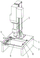
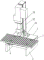
图1为本实用新型一种钢筋桁架楼承板强度测试装置的整体结构示意图;1 is a schematic diagram of the overall structure of a steel truss floor deck strength testing device of the present utility model;
图2为本实用新型一种钢筋桁架楼承板强度测试装置的调节结构处示意图;Fig. 2 is a schematic diagram of the adjusting structure of a steel truss floor deck strength testing device of the present invention;
图3为本实用新型一种钢筋桁架楼承板强度测试装置的螺纹杆处剖视图;3 is a cross-sectional view of a threaded rod of a steel truss floor deck strength testing device of the present invention;
图4为本实用新型一种钢筋桁架楼承板强度测试装置的限位压件示意图;Fig. 4 is a schematic diagram of a limiting pressure piece of a steel truss floor deck strength testing device of the present invention;
图5为本实用新型一种钢筋桁架楼承板强度测试装置的工作示意图;Fig. 5 is the working schematic diagram of the strength testing device of a steel truss floor deck of the present invention;
图6为本实用新型一种钢筋桁架楼承板强度测试装置的液压柱下端处剖视图;6 is a cross-sectional view at the lower end of a hydraulic column of a steel truss floor deck strength testing device of the present invention;
图7为本实用新型一种钢筋桁架楼承板强度测试装置的图6中A的放大图。FIG. 7 is an enlarged view of A in FIG. 6 of a strength testing device for a steel truss floor deck of the present invention.
图中:1、工作台;2、支撑座;3、冲压机构;31、固定板;32、固定柱;33、液压柱;34、压块;35、环槽;36、活动卡条;37、凸出板;38、压缩弹簧;39、活动腔;4、配合口;41、滑口;5、调节结构;51、活动条;52、凸出块;53、引导柱;54、螺纹杆;55、限位环;56、限位盘;57、螺纹筒;6、限位螺孔;7、限位压件;71、螺纹柱;72、压片;73、压紧螺母。In the figure: 1. Workbench; 2. Support seat; 3. Stamping mechanism; 31. Fixed plate; 32. Fixed column; 33. Hydraulic column; 34. Press block; 35. Ring groove; 36. Active clip; 37 , protruding plate; 38, compression spring; 39, movable cavity; 4, matching port; 41, sliding port; 5, adjusting structure; 51, movable bar; 52, protruding block; 53, guide column; 54, threaded rod ; 55, limit ring; 56, limit plate; 57, threaded barrel; 6, limit screw hole; 7, limit pressure piece; 71, threaded column;
具体实施方式Detailed ways
下面将结合本实用新型实施例中的附图,对本实用新型实施例中的技术方案进行清楚、完整地描述,显然,所描述的实施例仅仅是本实用新型一部分实施例,而不是全部的实施例。基于本实用新型中的实施例,本领域普通技术人员在没有做出创造性劳动前提下所获得的所有其他实施例,都属于本实用新型保护的范围。The technical solutions in the embodiments of the present utility model will be clearly and completely described below with reference to the accompanying drawings in the embodiments of the present utility model. Obviously, the described embodiments are only a part of the embodiments of the present utility model, rather than all the implementations. example. Based on the embodiments of the present invention, all other embodiments obtained by those of ordinary skill in the art without creative work fall within the protection scope of the present invention.
如图1-图7所示,一种钢筋桁架楼承板强度测试装置,包括工作台1与固定设置在下端外表面的支撑座2,工作台1的上端外表面开设有配合口4,配合口4的内侧滑动安装有调节结构5,工作台1的上端外表面靠近配合口4的后方设置有冲压机构3,其中:As shown in Figures 1-7, a steel truss floor deck strength test device includes a
调节结构5包括滑动设置在配合口4内侧的活动条51、活动设置在活动条51一侧外表面且穿过工作台1一侧外表面的螺纹杆54,螺纹杆54与工作台1之间螺纹配合,活动条51以及工作台1的上端外表面靠近配合口4的一侧处开设有限位螺孔6,限位螺孔6的内侧设置有限位压件7。The
限位螺孔6设置为相互平行的两组,且每组限位螺孔6均沿一条直线上分布,限位压件7的数量为四个,用以限制住钢筋桁架楼承板靠近拐角处的位置,提高稳固程度。The
限位压件7包括螺纹配合插入限位螺孔6内侧的螺纹柱71活动套在螺纹柱71外表面的压片72、螺纹配合方式套在螺纹柱71外表面的压紧螺母73,压紧螺母73位于压片72的上方,以确保压片72的稳固,不易松动。The
螺纹杆54的一端活动贯穿活动条51的一侧外表面,且螺纹杆54的一端固定连接有限位盘56,螺纹杆54的外表面固定套有限位环55,限位环55以及限位盘56分别活动贴合在活动条51的两侧外表面,螺纹杆54与活动条51之间通过限位盘56以及限位环55活动连接,防止螺纹杆54的一端在转动时脱离。One end of the threaded
工作台1的一侧外表面对应螺纹杆54的穿过位置嵌入设置有螺纹筒57,螺纹筒57与螺纹杆54之间螺纹配合,螺纹筒57与工作台1之间为固定连接,螺纹杆54可以转动并移动位置。A threaded
活动条51的一侧外表面远离螺纹杆54的前方延伸出引导柱53,且引导柱53活动贯穿于工作台1的一侧外表面,活动条51的前后两端延伸出凸出块52,配合口4的内壁上开设有滑口41,凸出块52滑动卡于滑口41的内侧,确保活动条51可以平稳水平滑动。A
冲压机构3包括固定板31、设置在固定板31上端外表面的固定柱32、设置在固定柱32前端外表面的液压柱33,固定板31的下端外表面与工作台1的上端外表面之间为固定连接,用来进行冲压测试。The
液压柱33的下端嵌入设置有压块34,压块34的外表面开设有环槽35,液压柱33的一侧外表面贯穿设置有活动卡条36,且活动卡条36的一端插入环槽35的内侧,活动卡条36的上端外表面延伸出凸出板37,液压柱33的内侧对应凸出板37的位置开设有活动腔39,活动腔39的内侧填入有压缩弹簧38。The lower end of the
需要说明的是,本实用新型为一种钢筋桁架楼承板强度测试装置,在使用时,使用者事先旋转并取下整个限位压件7,将板体放置在工作台1的表面,之后使用者将螺纹柱71穿过板体的交错空隙处,并旋入限位螺孔6的内侧,之后转动螺纹杆54,使得螺纹杆54转动,发生水平移动,同时使得活动条51共同滑动,直至活动条51上的螺纹柱71以及工作台1上的螺纹柱71将板体撑紧即可,从而防止板体发生滑动,提高测试精度,而使用者通过旋动压紧螺母73,直到压片72压紧板体的表面,在液压柱33冲压的过程中,压片72的压紧作用,防止板体冲压时两侧翘起而降低了对待检测位置板体的冲压效果,因此提升测试效果,抽动活动卡条36,使得压缩弹簧38受力挤压,从而使得活动卡条36脱离环槽35的内侧,之后即可将压块34向下拔出,而压块34的结构简单,易于批量生产,有利于冲压部分的更换,确保冲压效果。It should be noted that the present utility model is a strength testing device for a steel truss floor slab. When in use, the user rotates and removes the entire limiting
需要说明的是,在本文中,诸如第一和第二等之类的关系术语仅仅用来将一个实体或者操作与另一个实体或操作区分开来,而不一定要求或者暗示这些实体或操作之间存在任何这种实际的关系或者顺序。而且,术语“包括”、“包含”或者其任何其他变体意在涵盖非排他性的包含,从而使得包括一系列要素的过程、方法、物品或者设备不仅包括那些要素,而且还包括没有明确列出的其他要素,或者是还包括为这种过程、方法、物品或者设备所固有的要素。It should be noted that, in this document, relational terms such as first and second are only used to distinguish one entity or operation from another entity or operation, and do not necessarily require or imply any relationship between these entities or operations. any such actual relationship or sequence exists. Moreover, the terms "comprising", "comprising" or any other variation thereof are intended to encompass a non-exclusive inclusion such that a process, method, article or device that includes a list of elements includes not only those elements, but also includes not explicitly listed or other elements inherent to such a process, method, article or apparatus.
尽管已经示出和描述了本实用新型的实施例,对于本领域的普通技术人员而言,可以理解在不脱离本实用新型的原理和精神的情况下可以对这些实施例进行多种变化、修改、替换和变型,本实用新型的范围由所附权利要求及其等同物限定。Although the embodiments of the present invention have been shown and described, it will be understood by those skilled in the art that various changes and modifications can be made to these embodiments without departing from the principles and spirit of the present invention , alternatives and modifications, the scope of the present invention is defined by the appended claims and their equivalents.
Claims (8)
Priority Applications (1)
| Application Number | Priority Date | Filing Date | Title |
|---|---|---|---|
| CN202020524324.6U CN212008132U (en) | 2020-04-11 | 2020-04-11 | A kind of strength test device for steel truss floor deck |
Applications Claiming Priority (1)
| Application Number | Priority Date | Filing Date | Title |
|---|---|---|---|
| CN202020524324.6U CN212008132U (en) | 2020-04-11 | 2020-04-11 | A kind of strength test device for steel truss floor deck |
Publications (1)
| Publication Number | Publication Date |
|---|---|
| CN212008132U true CN212008132U (en) | 2020-11-24 |
Family
ID=73413574
Family Applications (1)
| Application Number | Title | Priority Date | Filing Date |
|---|---|---|---|
| CN202020524324.6U Expired - Fee Related CN212008132U (en) | 2020-04-11 | 2020-04-11 | A kind of strength test device for steel truss floor deck |
Country Status (1)
| Country | Link |
|---|---|
| CN (1) | CN212008132U (en) |
Cited By (1)
| Publication number | Priority date | Publication date | Assignee | Title |
|---|---|---|---|---|
| CN111337351A (en) * | 2020-04-11 | 2020-06-26 | 张家港市永茂住宅工业有限公司 | A kind of strength test device for steel truss floor deck |
-
2020
- 2020-04-11 CN CN202020524324.6U patent/CN212008132U/en not_active Expired - Fee Related
Cited By (2)
| Publication number | Priority date | Publication date | Assignee | Title |
|---|---|---|---|---|
| CN111337351A (en) * | 2020-04-11 | 2020-06-26 | 张家港市永茂住宅工业有限公司 | A kind of strength test device for steel truss floor deck |
| CN111337351B (en) * | 2020-04-11 | 2025-03-14 | 张家港市永茂住宅工业有限公司 | A steel truss floor deck strength testing device |
Similar Documents
| Publication | Publication Date | Title |
|---|---|---|
| CN206316791U (en) | The multi-diameter shaft end flat milling tool of bull-dozer | |
| CN207746748U (en) | A kind of thin wall curved guide clamp for machining | |
| CN202070809U (en) | New milling machine base | |
| CN211029028U (en) | Shaft end drilling tool | |
| CN207147909U (en) | A kind of detection means for being used to detect the hardness of construction material | |
| CN110052868A (en) | A kind of Combined all floating fixture | |
| CN205763508U (en) | A kind of head locking device of stirrup bender | |
| CN111337351A (en) | A kind of strength test device for steel truss floor deck | |
| CN204064761U (en) | Bending press | |
| CN219380618U (en) | a fixture | |
| CN211331979U (en) | Portable steel welding clamping device | |
| CN216954456U (en) | Paperboard production thickness detection device | |
| CN211317989U (en) | Auxiliary tool for detecting strength of touch screen plate | |
| CN209953561U (en) | A bending device for production of oil-immersed power transformer noise reduction device | |
| CN209550416U (en) | Automated rigid storage limiters for stamping dies | |
| CN218363526U (en) | Hydraulic mechanical chuck | |
| CN209062766U (en) | A grinding device for processing bamboo products | |
| CN208282732U (en) | A kind of combined type cubing | |
| CN211916009U (en) | Magnetic head size method pressing-in structure of automatic titanium strip assembling machine | |
| CN220805163U (en) | Cut-out press convenient to change | |
| CN207215549U (en) | A kind of pelleting press for plant chromosome film-making | |
| CN218577334U (en) | Novel bill binding machine | |
| CN220740090U (en) | A press machine that is easy to operate | |
| CN218489363U (en) | A bill flattening device for accounting | |
| CN211589058U (en) | A frock clamp for steel construction production |
Legal Events
| Date | Code | Title | Description |
|---|---|---|---|
| GR01 | Patent grant | ||
| GR01 | Patent grant | ||
| CF01 | Termination of patent right due to non-payment of annual fee |
Granted publication date: 20201124 |
|
| CF01 | Termination of patent right due to non-payment of annual fee |