CN212006808U - Manifold type air cooler capable of spraying - Google Patents
Manifold type air cooler capable of spraying Download PDFInfo
- Publication number
- CN212006808U CN212006808U CN202020269377.8U CN202020269377U CN212006808U CN 212006808 U CN212006808 U CN 212006808U CN 202020269377 U CN202020269377 U CN 202020269377U CN 212006808 U CN212006808 U CN 212006808U
- Authority
- CN
- China
- Prior art keywords
- box body
- water
- pipe
- fixed
- annular
- Prior art date
- Legal status (The legal status is an assumption and is not a legal conclusion. Google has not performed a legal analysis and makes no representation as to the accuracy of the status listed.)
- Expired - Fee Related
Links
Images

Landscapes
- Heat-Exchange Devices With Radiators And Conduit Assemblies (AREA)
Abstract
本实用新型公开了一种集合管式可喷淋空气冷却器,涉及空气冷却器技术领域。本实用新型包括矩形上端开口的箱体;箱体一相对侧面间贯穿固定有交错设置的热流导管;箱体上端面固定有聚风罩;聚风罩上端面固定有风机;箱体下端面贯穿固定有用于进气排水的导流管;还包括安装在箱体内的两个喷淋组件、以及用于两个喷淋组件供水的供水装置;供水装置包括水槽、管道泵;水槽与两个喷淋组件通过三通管连通;箱体安装在水槽内部,且箱体下端面固定有固定支撑腿。本实用新型通过喷淋组件与供水装置配合,两级喷水降温,下端回流降温,解决了现有喷淋式空气冷却器热交换效果不理想的问题。
The utility model discloses a manifold type sprayable air cooler, which relates to the technical field of air coolers. The utility model comprises a rectangular box body with an open upper end; heat flow conduits arranged staggeredly are fixed through one opposite side of the box body; an air collecting hood is fixed on the upper end surface of the box body; a fan is fixed on the upper end surface of the air collecting hood; A guide pipe for air intake and drainage is fixed; it also includes two spray assemblies installed in the box, and a water supply device for water supply to the two spray assemblies; the water supply device includes a water tank and a pipeline pump; The shower assembly is communicated through a three-way pipe; the box body is installed inside the water tank, and the lower end face of the box body is fixed with a fixed support leg. The utility model cooperates with the water supply device through the spray assembly, the cooling is performed by two-stage water spray, and the lower end is refluxed for cooling, which solves the problem that the heat exchange effect of the existing spray type air cooler is not ideal.
Description
技术领域technical field
本实用新型属于空气冷却器技术领域,特别是涉及一种集合管式可喷淋空气冷却器。The utility model belongs to the technical field of air coolers, in particular to a manifold type sprayable air cooler.
背景技术Background technique
空气冷却器是利用空气冷却热流体的换热器,管内的热流体通过管壁和翅片与管外空气进行换热,所用的空气通常由通风机供给,空气冷却器可用于冷却或冷凝,广泛应用于炼油、石油化工塔顶蒸气的冷凝、塔底油的冷却、各种反应生成物的冷却、循环气体的冷却和电站汽轮机排气的冷凝,工作压力可达69兆帕,但耗电量、噪声和占地面积均大,冷却效果受气候变化影响较大。喷淋式空气冷却器在喷淋时会出现喷淋水幕撞击横管造成水向外喷洒的情况,上半部热流导管热量较大,喷淋的水损失量较大,致使下半部的热流导管散热不足,水流回流散热不理想。The air cooler is a heat exchanger that uses air to cool the hot fluid. The hot fluid in the tube exchanges heat with the air outside the tube through the tube wall and fins. The air used is usually supplied by a fan. The air cooler can be used for cooling or condensation. It is widely used in oil refining, condensation of petrochemical tower top vapor, cooling of tower bottom oil, cooling of various reaction products, cooling of circulating gas and condensation of exhaust gas of power station steam turbines. The working pressure can reach 69 MPa, but it consumes electricity. The cooling effect is greatly affected by climate change. When spraying the spray air cooler, the spray water curtain will hit the horizontal pipe and cause the water to spray outward. Insufficient heat dissipation of heat flow ducts, and unsatisfactory heat dissipation of water flow backflow.
实用新型内容Utility model content
本实用新型的目的在于提供一种集合管式可喷淋空气冷却器,通过喷淋组件与供水装置配合,两级喷水降温,下端回流降温,解决了现有喷淋式空气冷却器热交换效果不理想的问题。The purpose of the present utility model is to provide a manifold type sprayable air cooler, through the cooperation of the spray component and the water supply device, the two-stage water spray cooling, the lower end reflux cooling, and the heat exchange of the existing spray type air cooler is solved. The problem of unsatisfactory effect.
为解决上述技术问题,本实用新型是通过以下技术方案实现的:In order to solve the above-mentioned technical problems, the utility model is realized through the following technical solutions:
本实用新型为一种集合管式可喷淋空气冷却器,包括矩形上端开口的箱体;所述箱体一相对侧面间贯穿固定有交错设置的热流导管;所述箱体上端面固定有聚风罩;所述聚风罩上端面固定有风机;所述箱体下端面贯穿固定有用于进气排水的导流管;还包括安装在箱体内的两个喷淋组件、以及用于两个喷淋组件供水的供水装置;所述供水装置包括水槽、管道泵;所述水槽与两个喷淋组件通过三通管连通;所述箱体安装在水槽内部,且箱体下端面固定有固定支撑腿;所述管道泵安装在与水槽连接的三通管支管上;所述箱体上端部内壁安装有除雾器;所述喷淋组件包括内外套设的第一环形管道与第二环形管道,以及环形均布安装在第一环形管道与第二环形管道下侧的喷头;所述第一环形管道与第二环形管道通过四个第一连接管连通;所述第二环形管道周侧固定连通有一个贯穿箱体侧壁且与三通管连通的第二连接管;所述热流导管在箱体内部分为上半部与下半部;两个所述喷淋组件分别安装在箱体内部的上半部与下半部。The utility model relates to a collecting pipe type sprayable air cooler, which comprises a rectangular box body with an open upper end; heat flow conduits arranged staggeredly are penetrated and fixed between opposite sides of the box body; an air hood; a fan is fixed on the upper end surface of the air collecting hood; a guide pipe for air intake and drainage is fixed through the lower end surface of the box body; it also includes two spray assemblies installed in the box body, and a A water supply device for water supply by a spray assembly; the water supply device includes a water tank and a pipeline pump; the water tank is communicated with two spray components through a three-way pipe; the box body is installed inside the water tank, and the lower end surface of the box body is fixed with a fixed support legs; the pipeline pump is installed on the branch pipe of the tee pipe connected with the water tank; the inner wall of the upper end of the box is installed with a mist eliminator; the spray assembly includes a first annular pipe and a second annular Pipes, and spray heads installed on the lower sides of the first annular pipe and the second annular pipe in an annular uniform distribution; the first annular pipe and the second annular pipe are communicated through four first connecting pipes; the peripheral side of the second annular pipe There is a second connecting pipe which penetrates through the side wall of the box body and communicates with the tee pipe in fixed communication; the heat flow conduit in the box body is an upper half and a lower half; the two spray assemblies are respectively installed in the box body The upper and lower halves of the interior.
进一步地,所述供水装置还包括蓄水箱、液位开关、电磁管道阀;所述蓄水箱设置在水槽一侧且通过补给水管与水槽连通;所述电磁管道阀安装在补给水管上;所述液位开关安装在水槽内侧壁。Further, the water supply device further comprises a water storage tank, a liquid level switch, and an electromagnetic pipeline valve; the water storage tank is arranged on one side of the water tank and communicated with the water tank through a supply water pipe; the electromagnetic pipeline valve is installed on the supply water pipe; The liquid level switch is installed on the inner side wall of the water tank.
进一步地,所述箱体下端部周侧面环形阵列开设进气孔。Further, air inlet holes are provided in an annular array on the peripheral side surface of the lower end of the box body.
进一步地,所述热流导管周侧面环形排列固定有沿轴向设置的翅片;所述翅片表面矩形阵列开有过水孔。Further, fins arranged in the axial direction are arranged and fixed in an annular array on the peripheral side surface of the heat flow conduit; and water passage holes are formed on the surface of the fins in a rectangular array.
本实用新型具有以下有益效果:The utility model has the following beneficial effects:
1、本实用新型供水装置中的两个喷淋组件,分别安装在热流导管上半部与下半部的上方,采用两级喷淋的方式,下侧的喷淋组件用于增加下半部的热流导管周侧的喷淋水量以及降低喷淋水的温度,整体提高热流导管的喷淋散热效率。1. The two spray assemblies in the water supply device of the present utility model are respectively installed above the upper half and the lower half of the heat flow conduit, adopting a two-stage spraying method, and the spray assembly on the lower side is used to increase the lower half. The amount of spray water on the peripheral side of the heat flow duct and the temperature of the spray water are reduced, so as to improve the spraying heat dissipation efficiency of the heat flow duct as a whole.
2、本实用新型通过蓄水箱、液位开关和电磁管道阀用于时刻补充水箱中的水,保障散热用水的持续稳定,以及降低回流水温提高水雾降温的高效。2. The utility model is used to replenish the water in the water tank at all times through the water storage tank, the liquid level switch and the electromagnetic pipeline valve, so as to ensure the continuous stability of the heat dissipation water, and to reduce the return water temperature and improve the efficiency of water mist cooling.
3、本实用新型通过在箱体下端面贯穿固定的用于进气排水的导流管,水流向下,气流向上,快速的对回流的水降温,提高水冷喷淋的效果。3. The utility model uses a fixed guide pipe for air intake and drainage through the lower end face of the box body, the water flows downwards and the air flow upwards, rapidly cooling the backflowing water and improving the effect of water cooling spray.
当然,实施本实用新型的任一产品并不一定需要同时达到以上所述的所有优点。Of course, any product implementing the present invention does not necessarily need to simultaneously achieve all of the above-mentioned advantages.
附图说明Description of drawings
为了更清楚地说明本实用新型实施例的技术方案,下面将对实施例描述所需要使用的附图作简单地介绍,显而易见地,下面描述中的附图仅仅是本实用新型的一些实施例,对于本领域普通技术人员来讲,在不付出创造性劳动的前提下,还可以根据这些附图获得其他的附图。In order to illustrate the technical solutions of the embodiments of the present invention more clearly, the accompanying drawings required for the description of the embodiments will be briefly introduced below. Obviously, the drawings in the following description are only some embodiments of the present invention. For those of ordinary skill in the art, other drawings can also be obtained from these drawings without creative effort.
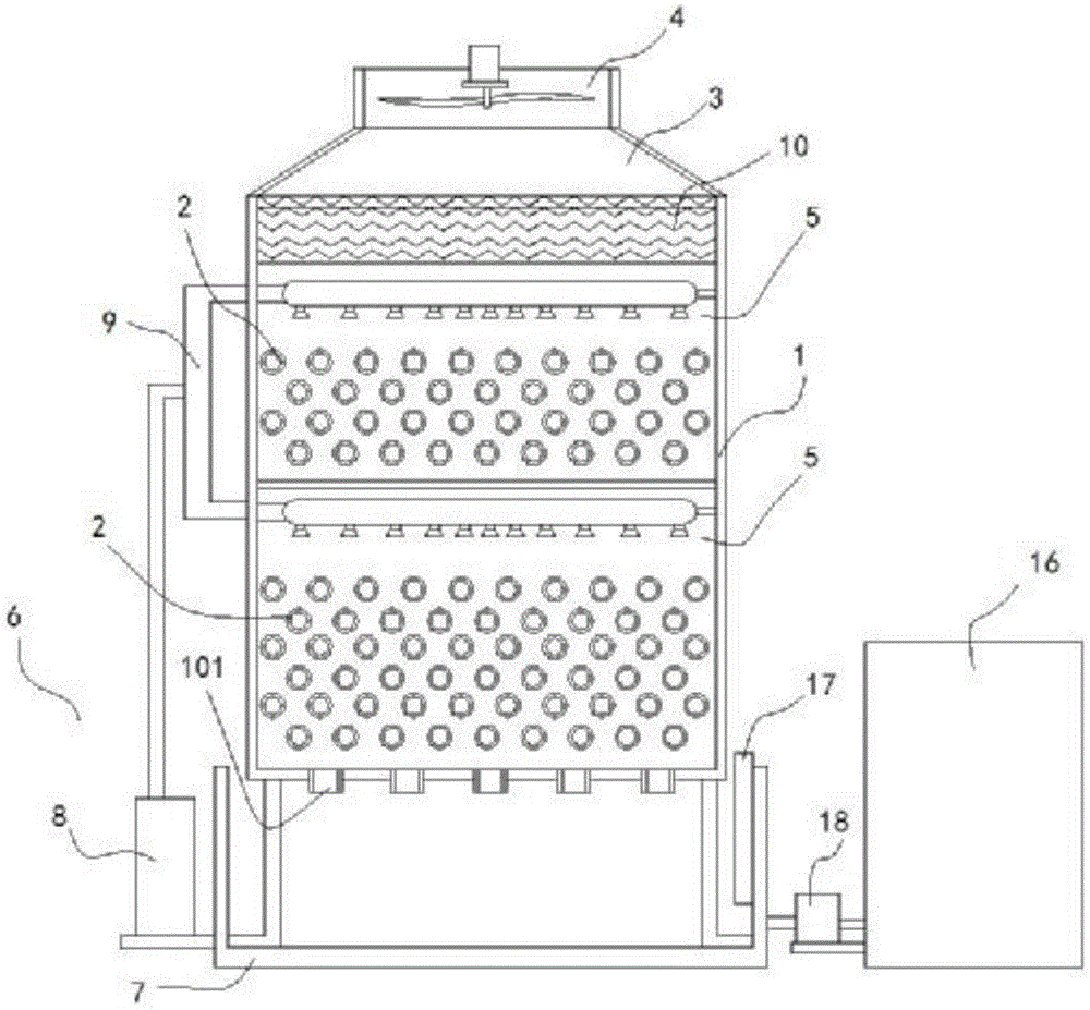
图1为本实用新型一种集合管式可喷淋空气冷却器的结构示意图;1 is a schematic structural diagram of a manifold type sprayable air cooler of the present invention;
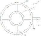
图2为喷淋组件的结构示意图;Figure 2 is a schematic structural diagram of a spray assembly;
附图中,各标号所代表的部件列表如下:In the accompanying drawings, the list of components represented by each number is as follows:
1-箱体,2-热流导管,3-聚风罩,4-风机,5-喷淋组件,6-供水装置,7-水槽,8-管道泵,9-三通管,10-除雾器,11-第一环形管道,12-第二环形管道,13-喷头,14-第一连接管,15-第二连接管,16-蓄水箱,17-液位开关,18-电磁管道阀,101-导流管。1-Box, 2-Heat flow duct, 3-Air collecting hood, 4-Fan, 5-Spray component, 6-Water supply device, 7-Sink, 8-Pipe pump, 9-Tee pipe, 10-Defogging device, 11-first annular pipe, 12-second annular pipe, 13-spray head, 14-first connecting pipe, 15-second connecting pipe, 16-water storage tank, 17-liquid level switch, 18-electromagnetic pipe Valve, 101 - Vent.
具体实施方式Detailed ways
下面将结合本实用新型实施例中的附图,对本实用新型实施例中的技术方案进行清楚、完整地描述,显然,所描述的实施例仅仅是本实用新型一部分实施例,而不是全部的实施例。基于本实用新型中的实施例,本领域普通技术人员在没有作出创造性劳动前提下所获得的所有其它实施例,都属于本实用新型保护的范围。The technical solutions in the embodiments of the present utility model will be clearly and completely described below with reference to the accompanying drawings in the embodiments of the present utility model. Obviously, the described embodiments are only a part of the embodiments of the present utility model, rather than all the implementations. example. Based on the embodiments of the present invention, all other embodiments obtained by those of ordinary skill in the art without creative work fall within the protection scope of the present invention.
请参阅图1-2所示,本实用新型为一种集合管式可喷淋空气冷却器,包括矩形上端开口的箱体1;箱体1一相对侧面间贯穿固定有交错设置的热流导管2;箱体1上端面固定有聚风罩3;聚风罩3上端面固定有风机4;箱体1下端面贯穿固定有用于进气排水的导流管101;还包括安装在箱体1内的两个喷淋组件5、以及用于两个喷淋组件5供水的供水装置6;供水装置6包括水槽7、管道泵8;水槽7与两个喷淋组件5通过三通管9连通;箱体1安装在水槽7内部,且箱体1下端面固定有固定支撑腿;管道泵8安装在与水槽7连接的三通管9支管上;箱体1上端部内壁安装有除雾器10;Please refer to FIGS. 1-2 , the utility model is a manifold type sprayable air cooler, comprising a box body 1 with a rectangular upper end opening;
喷淋组件5包括内外套设的第一环形管道11与第二环形管道12,以及环形均布安装在第一环形管道11与第二环形管道12下侧的喷头13;第一环形管道11与第二环形管道12通过四个第一连接管14连通;第二环形管道12周侧固定连通有一个贯穿箱体1侧壁且与三通管9连通的第二连接管15;The
热流导管2在箱体1内部分为上半部与下半部;两个喷淋组件5分别安装在箱体1内部的上半部与下半部。The
其中,供水装置6还包括蓄水箱16、液位开关17、电磁管道阀18;蓄水箱16设置在水槽7一侧且通过补给水管与水槽7连通;电磁管道阀18安装在补给水管上;液位开关17安装在水槽7内侧壁,设计的蓄水箱16、液位开关17和电磁管道阀18用于时刻补充水箱5中的水,保障散热用水的持续稳定,以及降低回流水温提高水雾降温的高效。The
其中,箱体1下端部周侧面环形阵列开设进气孔,增加气孔,降低风机4的工作压力。Among them, the annular array on the peripheral side surface of the lower end of the box body 1 is provided with air inlet holes, and the air holes are increased to reduce the working pressure of the fan 4 .
其中,热流导管2周侧面环形排列固定有沿轴向设置的翅片;翅片表面矩形阵列开有过水孔,过水孔用于将过多滞留的水分流至相邻的翅片或下一层的热流导管2,翅片增加了喷淋的水雾与热流导管2的接触面积,增加热交换面积,提高热交换效率。Among them, the fins arranged in the axial direction are arranged in an annular arrangement on the two sides of the heat flow conduit; the rectangular array on the surface of the fins is provided with water-passing holes, which are used to flow the excessively retained water to the adjacent fins or lower parts. The
喷淋组件5的数量为两个,分别安装在热流导管2上半部与下半部的上方,采用两级喷淋的方式,上半部热流导管2热量较大,喷淋的水损失量较大,下侧的喷淋组件5用于增加下半部的热流导管2周侧的喷淋水量以及降低喷淋水的温度,整体提高热流导管2的喷淋散热效率;箱体1下端面贯穿固定的用于进气排水的导流管101,水流向下,气流向上,快速的对回流的水降温,提高水冷喷淋的效果。The number of
在本说明书的描述中,参考术语“一个实施例”、“示例”、“具体示例”等的描述意指结合该实施例或示例描述的具体特征、结构、材料或者特点包含于本实用新型的至少一个实施例或示例中。在本说明书中,对上述术语的示意性表述不一定指的是相同的实施例或示例。而且,描述的具体特征、结构、材料或者特点可以在任何的一个或多个实施例或示例中以合适的方式结合。In the description of this specification, description with reference to the terms "one embodiment", "example", "specific example", etc. means that a specific feature, structure, material or characteristic described in connection with the embodiment or example is included in the present invention. in at least one embodiment or example. In this specification, schematic representations of the above terms do not necessarily refer to the same embodiment or example. Furthermore, the particular features, structures, materials or characteristics described may be combined in any suitable manner in any one or more embodiments or examples.
以上公开的本实用新型优选实施例只是用于帮助阐述本实用新型。优选实施例并没有详尽叙述所有的细节,也不限制该实用新型仅为所述的具体实施方式。显然,根据本说明书的内容,可作很多的修改和变化。本说明书选取并具体描述这些实施例,是为了更好地解释本实用新型的原理和实际应用,从而使所属技术领域技术人员能很好地理解和利用本实用新型。本实用新型仅受权利要求书及其全部范围和等效物的限制。The preferred embodiments of the present invention disclosed above are only used to help illustrate the present invention. The preferred embodiments do not describe all the details, nor do they limit the invention to only the described embodiments. Obviously, many modifications and variations are possible in light of the contents of this specification. This specification selects and specifically describes these embodiments in order to better explain the principle and practical application of the present invention, so that those skilled in the art can well understand and utilize the present invention. The present invention is limited only by the claims and their full scope and equivalents.
Claims (4)
Priority Applications (1)
| Application Number | Priority Date | Filing Date | Title |
|---|---|---|---|
| CN202020269377.8U CN212006808U (en) | 2020-03-07 | 2020-03-07 | Manifold type air cooler capable of spraying |
Applications Claiming Priority (1)
| Application Number | Priority Date | Filing Date | Title |
|---|---|---|---|
| CN202020269377.8U CN212006808U (en) | 2020-03-07 | 2020-03-07 | Manifold type air cooler capable of spraying |
Publications (1)
| Publication Number | Publication Date |
|---|---|
| CN212006808U true CN212006808U (en) | 2020-11-24 |
Family
ID=73424098
Family Applications (1)
| Application Number | Title | Priority Date | Filing Date |
|---|---|---|---|
| CN202020269377.8U Expired - Fee Related CN212006808U (en) | 2020-03-07 | 2020-03-07 | Manifold type air cooler capable of spraying |
Country Status (1)
| Country | Link |
|---|---|
| CN (1) | CN212006808U (en) |
Cited By (2)
| Publication number | Priority date | Publication date | Assignee | Title |
|---|---|---|---|---|
| CN113266998A (en) * | 2021-06-30 | 2021-08-17 | 中国有色(沈阳)冶金机械有限公司 | Drum-type high-temperature material cooling system |
| CN120846111A (en) * | 2025-09-19 | 2025-10-28 | 福建圣农发展股份有限公司 | A split-flow heat-conducting air-cooled heat exchanger structure |
-
2020
- 2020-03-07 CN CN202020269377.8U patent/CN212006808U/en not_active Expired - Fee Related
Cited By (2)
| Publication number | Priority date | Publication date | Assignee | Title |
|---|---|---|---|---|
| CN113266998A (en) * | 2021-06-30 | 2021-08-17 | 中国有色(沈阳)冶金机械有限公司 | Drum-type high-temperature material cooling system |
| CN120846111A (en) * | 2025-09-19 | 2025-10-28 | 福建圣农发展股份有限公司 | A split-flow heat-conducting air-cooled heat exchanger structure |
Similar Documents
| Publication | Publication Date | Title |
|---|---|---|
| CN103134344B (en) | Open-close type energy-saving cooling tower | |
| CN105403068B (en) | Cooling tower and its application are combined using the dry and wet of gravity-flow ventilation and combined running pattern | |
| CN209431910U (en) | A kind of high-efficiency cooling tower | |
| CN201141732Y (en) | A constant temperature evaporative cooler | |
| CN201740135U (en) | Tube-type indirect evaporative high-temperature chiller plant | |
| CN204301556U (en) | A kind of nested type double tower body double flash evaporation cooling tower | |
| CN207963544U (en) | A kind of energy-efficient cooling tower | |
| CN1963369A (en) | Evaporative closed cooling tower | |
| CN103471422B (en) | Open and close type energy-saving cooling tower | |
| CN212006809U (en) | Manifold water mist type efficient air cooler | |
| CN204593678U (en) | Based on the enclosed evaporative cooling handpiece Water Chilling Units of civil engineering structure | |
| CN213515155U (en) | Compound closed fog dispersal water-saving cooling tower | |
| CN206670401U (en) | Efficient quick-cooking type closed cooling tower | |
| CN205316531U (en) | Evaporation cooling temperature humidity independent control fresh air unit | |
| CN205002625U (en) | Fixed filler cooling tower that sprays | |
| CN214403691U (en) | A combined spray vacuum device inside and outside the pipeline of a direct air cooling unit | |
| CN204694113U (en) | The special cooler of a kind of closed cooling tower | |
| CN208153074U (en) | A Cooling System Applied to Circumferential Steam Injection of Low Pressure Cylinder of 200MW Three-cylinder Three-row Steam Turbine | |
| CN224004249U (en) | Double air inlet countercurrent type closed cooling tower | |
| CN207095100U (en) | A kind of evaporative condenser | |
| CN223388969U (en) | Dry-wet combined cooling tower | |
| CN213901996U (en) | Wave curved plate type evaporative cooler | |
| CN207556317U (en) | A kind of air cooling plate heat exchanger | |
| CN206626981U (en) | A kind of re-pasteurization cools down water-cooling circulating device | |
| CN222165770U (en) | Closed cooling tower |
Legal Events
| Date | Code | Title | Description |
|---|---|---|---|
| GR01 | Patent grant | ||
| GR01 | Patent grant | ||
| CF01 | Termination of patent right due to non-payment of annual fee |
Granted publication date: 20201124 |
|
| CF01 | Termination of patent right due to non-payment of annual fee |