CN212006082U - Novel cooling dust exhausting fan - Google Patents
Novel cooling dust exhausting fan Download PDFInfo
- Publication number
- CN212006082U CN212006082U CN202020836750.3U CN202020836750U CN212006082U CN 212006082 U CN212006082 U CN 212006082U CN 202020836750 U CN202020836750 U CN 202020836750U CN 212006082 U CN212006082 U CN 212006082U
- Authority
- CN
- China
- Prior art keywords
- shell
- air
- fixedly connected
- pipe
- water tank
- Prior art date
- Legal status (The legal status is an assumption and is not a legal conclusion. Google has not performed a legal analysis and makes no representation as to the accuracy of the status listed.)
- Active
Links
Images


Abstract
The utility model discloses a novel cooling dust exhausting fan, including the shell, remove wheel, tool rest and fan body, remove the wheel and be provided with four and fix the bottom at the shell, beneficial effect is: this device is through being provided with the inflator, be provided with the aviation baffle in the inflator, can make the inspiratory air of fan body upwards blow away under the effect of aviation baffle, filter wherein impurity back through the filter, blow in the pressure boost pipe, this kind of design, can adsorb filtration treatment to the impurity in the air, through being provided with the water tank etc., the pressure boost pipe is with inside air transportation to the water tank, thereby increase the inside atmospheric pressure of water tank, make water carry to the nozzle through the outlet pipe, spraying by the nozzle is gone out, thereby realized this function of cooling after removing dust, thereby the effectual practicality that has increased the device.
Description
Technical Field
The utility model relates to an air purification field specifically is a novel cooling dust exhausting fan.
Background
Among the prior art, in the building work progress, dust and temperature on the construction ground are higher, and traditional dust exhausting fan mostly only has the function of removing dust, if need the cooling, then need be equipped with watering device in addition, and building site construction space is limited, places multiple equipment and influences the construction easily, consequently the utility model provides a novel cooling dust exhausting fan.
Disclosure of Invention
An object of the utility model is to provide a novel cooling dust exhausting fan to solve the problem that proposes in the above-mentioned background art.
In order to achieve the above object, the utility model provides a following technical scheme:
a novel cooling and dedusting fan comprises a shell, a moving wheel, a tool rack and a fan body, wherein the moving wheel is provided with four wheels and fixed at the bottom of the shell, the tool rack is installed at one side of the bottom of the shell, the fan body is arranged in the shell, the bottom of the fan body is fixedly connected with the inner wall of the shell through a bracket, one side of the fan body is fixedly communicated with an air suction pipe, the air suction pipe is inserted on the shell, one end of the air suction pipe, which is arranged outside the shell, is fixedly connected with an air suction hood, one side of the fan body, which is far away from the air suction pipe, is fixedly communicated with an exhaust pipe, one end of the exhaust pipe, which is far away from the fan body, is fixedly communicated with an exhaust nozzle, the outer sleeve is fixedly connected with the outer sleeve, one side of the outer sleeve is fixedly communicated with an inflator, the inflator is fixedly installed on the inner wall, a filter plate is arranged above the air deflector, one end of the filter plate, which is far away from the air deflector, is fixedly connected with the inner wall of the air cylinder, a collecting box is arranged below the air cylinder, the top of the collecting box is in contact with the bottom of the air cylinder, a collecting tank is chiseled at the top of the collecting box and is mutually communicated with the interior of the air cylinder, a plurality of hand fasteners are arranged on the front surface of the collecting box, a plurality of clamping blocks are fixedly connected with the bottom of the collecting box, the clamping blocks are oppositely inserted on the clamping plates, the clamping plates are fixedly arranged at the inner bottom of the shell, the top of the air cylinder is fixedly communicated with a water tank through a pressurizing pipe, the water tank is fixedly arranged on the inner wall of the shell, a one-way valve is arranged on the pressurizing pipe, a water inlet pipe is fixedly communicated with the top of the water tank, the improved water-saving hand-operated water dispenser is characterized in that a corrugated pipe is arranged on the water outlet pipe, the water outlet pipe is arranged on a connecting plate fixedly connected to the side face of one end outside the shell, a threaded rod is movably inserted into the connecting plate, a hand ring is fixedly connected to the top of the threaded rod, a limiting plate is fixedly connected to the outer side of the threaded rod between the hand ring and the connecting plate, the bottom end of the threaded rod is in threaded connection with a threaded sleeve at the top of the shell, and the connecting plate is.
As a further aspect of the present invention, the clip plate is fixedly mounted on the inner bottom of the housing.
As the utility model discloses scheme further again, through spring fixed connection between connecting plate and the shell, keep away from the one end fixedly connected with nozzle of water tank on the outlet pipe.
As the utility model discloses further scheme again, be provided with the cabinet door on collecting box one side shell, through a plurality of hinge swing joint between cabinet door and the shell.
As the utility model discloses further scheme again, the cross sectional dimension of limiting plate is greater than the cross sectional dimension of threaded rod and connecting plate junction.
As a further proposal of the utility model, the inlet tube is fixedly inserted on the shell, the top end threaded connection of the inlet tube has the rotary torsion cover.
Advantageous effects
Compared with the prior art, the beneficial effects of the utility model are that:
1. the utility model discloses in, through being provided with the inflator, be provided with the aviation baffle in the inflator, can make the inspiratory air of fan body upwards blow away under the effect of aviation baffle, filter wherein impurity through the filter after, blow in the pressure boost pipe, this kind of design can adsorb filtration processing to the impurity in the air.
2. Through being provided with the water tank etc. pressure boost pipe is with inside air transportation to the water tank to increase the inside atmospheric pressure of water tank, make water carry to the nozzle through the outlet pipe, spraying by the nozzle is gone out, thereby realized can cooling down this function after removing dust, thereby the effectual practicality that has increased the device.
Drawings
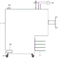
Fig. 1 is a schematic structural view of the present invention;
fig. 2 is a schematic external structural view of the present invention;
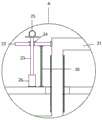
FIG. 3 is a schematic structural view of the position A of the present invention;
fig. 4 is a schematic structural view of the collecting box of the present invention.
In the figure: 1. a housing; 2. a moving wheel; 3. a tool holder; 4. a fan body; 5. an air suction pipe; 6. an air suction hood; 7. an exhaust duct; 8. an exhaust nozzle; 9. an outer sleeve; 10. an air cylinder; 11. an air deflector; 12. a filter plate; 13. a collection box; 14. collecting tank; 15. c, hand buckling; 16. a clamping block; 17. clamping a plate; 18. a pressure increasing pipe; 19. a water tank; 20. a water inlet pipe; 21. a water outlet pipe; 22. a connecting plate; 23. a threaded rod; 24. a limiting plate; 25. a bracelet; 26. a threaded sleeve; 27. a nozzle; 28. a cabinet door; 29. a support; 30. a spring.
Detailed Description
The technical solutions in the embodiments of the present invention will be described clearly and completely with reference to the accompanying drawings in the embodiments of the present invention, and it is obvious that the described embodiments are only some embodiments of the present invention, not all embodiments. Based on the embodiments in the present invention, all other embodiments obtained by a person skilled in the art without creative work belong to the protection scope of the present invention.
Referring to fig. 1-4, in the embodiment of the present invention, a novel cooling and dust removing fan comprises a housing 1, a moving wheel 2, a tool rack 3 and a fan body 4, wherein the moving wheel 2 is provided with four moving wheels and fixed at the bottom of the housing 1, the tool rack 3 is installed at one side of the bottom of the housing 1, the fan body 4 is arranged inside the housing 1, the bottom of the fan body 4 is fixedly connected with the inner wall of the housing 1 through a bracket 29, an air suction pipe 5 is fixedly communicated with one side of the fan body 4, the air suction pipe 5 is inserted on the housing 1, an air suction hood 6 is fixedly connected with one end of the air suction pipe 5 arranged outside the housing 1, an exhaust pipe 7 is fixedly communicated with one side of the fan body 4 far away from the air suction pipe 5, an exhaust nozzle 8 is fixedly communicated with one end of the exhaust pipe 7 far away from the fan body 4, an outer sleeve 9 is fixedly connected with, the inflator 10 is fixedly arranged on the inner wall of the shell 1, the outer sleeve 9 is arranged on the inner walls of the inflator 10 at the upper side and the lower side in the inflator 10, a pair of air deflectors 11 is arranged on the inner walls of the air deflectors 11, a filter plate 12 is arranged above the air deflectors 11, one end of the filter plate 12, far away from the air deflectors 11, is fixedly connected with the inner wall of the inflator 10, a collection box 13 is arranged below the inflator 10, the top of the collection box 13 is in contact with the bottom of the inflator 10, a collection groove 14 is chiseled at the top of the collection box 13, the collection groove 14 is communicated with the interior of the inflator 10, a plurality of hand fasteners 15 are arranged on the front surface of the collection box 13, a plurality of fixture blocks 16 are fixedly connected at the bottom of the collection box 13, the fixture blocks 16 are inserted on the fixture blocks 17, the fixture blocks 17 are clamped with the fixture blocks 16, the installation and the disassembly of the collection box 13 can be more, water tank 19 fixed mounting is on the inner wall of shell 1, be provided with the check valve on the pressure boost pipe 18, thereby the water backward flow that the design of check valve was avoided and ensure that the air gets into the inside pressure that increases in water tank 19 of water tank 19, the fixed intercommunication in top of water tank 19 has inlet tube 20, the fixed intercommunication in water tank 19 one side has outlet pipe 21, outlet pipe 21 activity is inserted and is established on shell 1, be provided with the bellows on the outlet pipe 21, outlet pipe 21 sets up at the outside one end side fixedly connected with connecting plate 22 of shell 1, threaded rod 23 is inserted in the activity on connecting plate 22, the top fixedly connected with handle ring 25 of threaded rod 23, the threaded rod 23 outside fixedly connected with limiting plate 24 between handle ring 25 and the connecting plate 22, the bottom of threaded rod 23 and the threaded sleeve 26 threaded connection at shell 1 top, pass through spring 30.
Collect and be provided with cabinet door 28 on box 13 one side shell 1, through a plurality of hinge swing joint between cabinet door 28 and the shell 1, cardboard 17 fixed mounting is at the interior bottom of shell 1, inlet tube 20 is fixed to be inserted and is established on shell 1, the top threaded connection of inlet tube 20 has the rotation to turn round the lid, through spring 30 fixed connection between connecting plate 22 and the shell 1, the one end fixedly connected with nozzle 27 of keeping away from water tank 19 on the outlet pipe 21, the cross sectional dimension of limiting plate 24 is greater than the cross sectional dimension of threaded rod 23 and connecting plate 22 junction.
The utility model discloses a theory of operation is: the device is moved to a designated position by moving the wheel 2, the fan body 4 is started, the fan body 4 works, air on one side of the air suction hood 6 is sucked into the air suction pipe 5, the air is conveyed to the exhaust pipe 7 and conveyed into the air cylinder 10 by the air exhaust nozzle 8, the air sucked by the fan body 4 is blown upwards under the action of the air deflector 11, impurities in the air are filtered by the filter plate 12 and then blown into the booster pipe 18, the impurities in the air can be adsorbed and filtered, the filtered impurities fall into the collecting tank 14 at the top of the collecting box 13 under the action of the filter plate 12 and the air deflector 11 to be collected, after a period of time, the cabinet door 28 is opened, the collecting box 13 is taken out by holding the hand buckle 15 to be cleaned, the booster pipe 18 conveys the air into the water tank 19 through the arrangement of the water tank 19 and the like, so that the air pressure in the water tank 19 is increased, and the water is conveyed to the, spraying by nozzle 27 to realize this function of cooling down after removing dust, thereby the effectual practicality that has increased the device, and in nozzle 27 working process, can utilize threaded rod 23 to reciprocate in threaded sleeve 26 through handle ring 25 rotatory threaded rod 23, and then drive connecting plate 22 through limiting plate 24 and reciprocate, thereby make nozzle 27 reciprocate along with connecting plate 22, and then adjust nozzle 27's the scope of spraying.
The above, only be the concrete implementation of the preferred embodiment of the present invention, but the protection scope of the present invention is not limited thereto, and any person skilled in the art is in the technical scope of the present invention, according to the technical solution of the present invention and the utility model, the concept of which is equivalent to replace or change, should be covered within the protection scope of the present invention.
Claims (6)
1. A novel cooling dust removal fan comprises a shell (1), four moving wheels (2), a tool rack (3) and a fan body (4), and is characterized in that the four moving wheels (2) are arranged and fixed at the bottom of the shell (1), the tool rack (3) is installed at one side of the bottom of the shell (1), the fan body (4) is arranged inside the shell (1), the bottom of the fan body (4) is fixedly connected with the inner wall of the shell (1) through a support (29), an air suction pipe (5) is fixedly communicated with one side of the fan body (4), the air suction pipe (5) is inserted into the shell (1), one end of the air suction pipe (5) arranged outside the shell (1) is fixedly connected with an air suction hood (6), and an exhaust pipe (7) is fixedly communicated with one side of the fan body (4) far away from the air suction pipe (5), an air exhaust nozzle (8) is fixedly communicated with one end of the air exhaust pipe (7) far away from the fan body (4), an outer sleeve (9) is fixedly connected to the outer portion of the air exhaust nozzle (8), one side of the outer sleeve (9) is fixedly communicated with the air cylinder (10), the air cylinder (10) is fixedly installed on the inner wall of the shell (1), a pair of air deflectors (11) are arranged on the inner walls of the air cylinder (10) on the upper side and the lower side of the inner portion of the air cylinder (10) of the outer sleeve (9), a filter plate (12) is arranged above the air deflectors (11), one end of the filter plate (12) far away from the air deflectors (11) is fixedly connected with the inner wall of the air cylinder (10), a collection box (13) is arranged below the air cylinder (10), the top of the collection box (13) is in contact with the bottom of the air cylinder (10), and a collection groove (14) is formed, collecting vat (14) and inflator (10) inside intercommunication each other, be provided with a plurality of hand fasteners (15) on the front of collecting box (13), a plurality of fixture blocks (16) of bottom fixedly connected with of collecting box (13), fixture block (16) are all to establishing on cardboard (17) with inserting, cardboard (17) fixed mounting is at the interior bottom of shell (1), the top of inflator (10) is through pressure boost pipe (18) fixed intercommunication have water tank (19), water tank (19) fixed mounting is on the inner wall of shell (1), be provided with the check valve on pressure boost pipe (18), the fixed intercommunication in top of water tank (19) has inlet tube (20), water tank (19) one side fixed intercommunication has outlet pipe (21), outlet pipe (21) activity is inserted and is established on shell (1), be provided with the bellows on outlet pipe (21), outlet pipe (21) set up in the outside one end side fixedly connected with connecting plate (22) of shell (1) (22) ) The improved handle bar is characterized in that a threaded rod (23) is movably inserted into the connecting plate (22), a handle ring (25) is fixedly connected to the top of the threaded rod (23), a limiting plate (24) is fixedly connected to the outer side of the threaded rod (23) between the handle ring (25) and the connecting plate (22), the bottom end of the threaded rod (23) is in threaded connection with a threaded sleeve (26) at the top of the shell (1), and the connecting plate (22) is fixedly connected with the shell (1) through a spring (30).
2. The novel cooling and dedusting fan as claimed in claim 1, characterized in that: the clamping plate (17) is fixedly arranged at the inner bottom of the shell (1).
3. The novel cooling and dedusting fan as claimed in claim 1, characterized in that: the connecting plate (22) is fixedly connected with the shell (1) through a spring (30), and one end, far away from the water tank (19), of the water outlet pipe (21) is fixedly connected with a nozzle (27).
4. The novel cooling and dedusting fan as claimed in claim 1, characterized in that: a cabinet door (28) is arranged on the shell (1) on one side of the collecting box (13), and the cabinet door (28) is movably connected with the shell (1) through a plurality of hinges.
5. The novel cooling and dedusting fan as claimed in claim 1, characterized in that: the cross-sectional dimension of the limiting plate (24) is larger than that of the joint of the threaded rod (23) and the connecting plate (22).
6. The novel cooling and dedusting fan as claimed in claim 1, characterized in that: the water inlet pipe (20) is fixedly inserted on the shell (1), and the top end of the water inlet pipe (20) is in threaded connection with a rotary twist cover.
Priority Applications (1)
| Application Number | Priority Date | Filing Date | Title |
|---|---|---|---|
| CN202020836750.3U CN212006082U (en) | 2020-05-19 | 2020-05-19 | Novel cooling dust exhausting fan |
Applications Claiming Priority (1)
| Application Number | Priority Date | Filing Date | Title |
|---|---|---|---|
| CN202020836750.3U CN212006082U (en) | 2020-05-19 | 2020-05-19 | Novel cooling dust exhausting fan |
Publications (1)
| Publication Number | Publication Date |
|---|---|
| CN212006082U true CN212006082U (en) | 2020-11-24 |
Family
ID=73417211
Family Applications (1)
| Application Number | Title | Priority Date | Filing Date |
|---|---|---|---|
| CN202020836750.3U Active CN212006082U (en) | 2020-05-19 | 2020-05-19 | Novel cooling dust exhausting fan |
Country Status (1)
| Country | Link |
|---|---|
| CN (1) | CN212006082U (en) |
Cited By (1)
| Publication number | Priority date | Publication date | Assignee | Title |
|---|---|---|---|---|
| CN115228218A (en) * | 2022-06-13 | 2022-10-25 | 青岛环城建工集团有限公司 | Multi-angle rotatable multifunctional heatstroke prevention dust removal water sprinkling device for building construction |
-
2020
- 2020-05-19 CN CN202020836750.3U patent/CN212006082U/en active Active
Cited By (1)
| Publication number | Priority date | Publication date | Assignee | Title |
|---|---|---|---|---|
| CN115228218A (en) * | 2022-06-13 | 2022-10-25 | 青岛环城建工集团有限公司 | Multi-angle rotatable multifunctional heatstroke prevention dust removal water sprinkling device for building construction |
Similar Documents
| Publication | Publication Date | Title |
|---|---|---|
| CN212006082U (en) | Novel cooling dust exhausting fan | |
| CN210303003U (en) | Dust collector for construction | |
| CN214439999U (en) | Novel wet electrostatic precipitator | |
| CN212548843U (en) | Dust collecting equipment for municipal construction | |
| CN210544081U (en) | Dust remover for grinding inner wall of steel pipe | |
| CN211073077U (en) | Wet-type polishing dust removal all-in-one | |
| CN209952506U (en) | Low-cost efficient dust collector | |
| CN107812433A (en) | A kind of high-efficiency environment friendly cleaner | |
| CN208121666U (en) | A kind of efficient dust exhaust apparatus of construction | |
| CN210645704U (en) | Smoke dust processor for sculpture workshop | |
| CN217004816U (en) | High-efficient wet dust collecting equipment | |
| CN2491738Y (en) | Mechanical fume and smoke purifier | |
| CN216932944U (en) | High-efficient environment-friendly industrial dust collector | |
| CN218554533U (en) | High-pressure airless spraying machine | |
| CN209828606U (en) | Dust extraction for ceramic machining | |
| CN214437610U (en) | Dust remover convenient to remove | |
| CN211585747U (en) | Compound exhaust-gas treatment equipment | |
| CN213643584U (en) | High-efficient wet dust collector | |
| CN210544113U (en) | Weaving is with weaving quick-witted weaving dirt collection device | |
| CN219563762U (en) | Wet dust collector of brick cutting machine | |
| CN213421149U (en) | Boiler dust removal environmental protection equipment | |
| CN213433661U (en) | Tail gas collection and treatment device is retrieved to tailing | |
| CN214404135U (en) | Energy-saving dust exhausting fan | |
| CN218687793U (en) | Heat accumulating type oxidation furnace with waste gas treatment function | |
| CN216986766U (en) | Combined silicon dioxide powder collecting cover |
Legal Events
| Date | Code | Title | Description |
|---|---|---|---|
| GR01 | Patent grant | ||
| GR01 | Patent grant |