CN211993999U - Injection mold for anti-electric shock ferrule socket - Google Patents
Injection mold for anti-electric shock ferrule socket Download PDFInfo
- Publication number
- CN211993999U CN211993999U CN202020580923.XU CN202020580923U CN211993999U CN 211993999 U CN211993999 U CN 211993999U CN 202020580923 U CN202020580923 U CN 202020580923U CN 211993999 U CN211993999 U CN 211993999U
- Authority
- CN
- China
- Prior art keywords
- cavity
- injection
- cooling water
- template
- chamber
- Prior art date
- Legal status (The legal status is an assumption and is not a legal conclusion. Google has not performed a legal analysis and makes no representation as to the accuracy of the status listed.)
- Active
Links
Images


Landscapes
- Moulds For Moulding Plastics Or The Like (AREA)
Abstract
本实用新型公开了一种防触电插芯插座注塑模具,包括底板,所述底板的顶部固定安装有定模板,定模板的上方设有连接板,连接板的底部固定安装有动模板,定模板的顶部开设有第一注塑腔,第一注塑腔内固定安装有第一模仁,动模板的底部开设有第二注塑腔,第二注塑腔内固定安装有第二模仁,第二注塑腔与第一注塑腔相连通。本实用新型设计合理,实用性好,能够对动模板与定模板合模时产生的冲击力进行有效缓冲,避免动模板与定模板长期受到合模时产生的冲击力而受损坏,并且可对注塑成型的物件进行快速的冷却降温,加快物件的成型,提高了工作效率,而且便于动模板与定模板进行顺利脱模,方便取出成型物件。

The utility model discloses an injection mold for an electric shock-proof ferrule socket. A first injection cavity is opened at the top of the movable platen, a first mold core is fixedly installed in the first injection cavity, a second injection cavity is opened at the bottom of the movable platen, a second injection cavity is fixedly installed in the second injection cavity, and the second injection cavity communicated with the first injection cavity. The utility model has reasonable design and good practicability, can effectively buffer the impact force generated when the movable template and the fixed template are closed, avoid the moving template and the fixed template from being damaged by the impact force generated when the movable template and the fixed template are closed for a long time, and can The injection-molded objects are rapidly cooled and cooled, which speeds up the molding of the objects, improves the work efficiency, and facilitates the smooth demoulding of the movable template and the fixed template, and facilitates the removal of the molded objects.
Description
技术领域technical field
本实用新型涉及模具技术领域,具体为一种防触电插芯插座注塑模具。The utility model relates to the technical field of molds, in particular to an injection mold for an electric shock-proof ferrule socket.
背景技术Background technique
注塑模具是一种生产塑胶制品的工具,也是赋予塑胶制品完整结构和精确尺寸的工具,注塑成型是批量生产某些形状复杂部件时用到的一种加工方法,具体指将受热融化的塑料由注塑机高压射入模腔,经冷却固化后,得到成形品,注塑模具是由定模板和动模板组成,现今,在生产防触电插芯插座时,需要使用到注塑模具对生产防触电插芯插座的原料进行注塑成型,然后再进行下一道加工工序的生产。Injection mold is a tool for producing plastic products, and it is also a tool for imparting complete structure and precise dimensions to plastic products. Injection molding is a processing method used in mass production of some complex shapes. The injection molding machine injects high pressure into the mold cavity, and after cooling and solidifying , a molded product is obtained. The injection mold is composed of a fixed template and a moving template. Nowadays, when producing an electric shock-proof ferrule socket, an injection mold is required to produce an electric-shock-proof ferrule. The raw material of the socket is injection molded, and then the production of the next processing step is carried out.
但是,现有技术中,常用的注塑模具对防触电插芯插座进行生产过程中,对注塑成型的物件冷却降温效果不佳,对物件的冷却速度慢,导致工作效率降低,而且在注塑成型后,动模板和定模板之间容易粘合,不便于把动模板和定模板之间进行顺利脱模,给工作人员的工作带来不便,为此,我们提出一种防触电插芯插座注塑模具用于解决上述问题。However, in the prior art, during the production process of the anti-shock ferrule socket by the commonly used injection mold, the cooling effect of the injection-molded object is not good, and the cooling speed of the object is slow, resulting in a decrease in work efficiency, and after injection molding , It is easy to bond between the movable template and the fixed template, and it is not convenient to smoothly demold the movable template and the fixed template, which brings inconvenience to the work of the staff. For this reason, we propose an injection mold for electric shock-proof ferrule socket used to solve the above problems.
实用新型内容Utility model content
(一)解决的技术问题(1) Technical problems solved
针对现有技术的不足,本实用新型提供了一种防触电插芯插座注塑模具,解决了注塑模具对防触电插芯插座生产过程中,对注塑成型的物件冷却降温效果不佳,对物件的冷却速度慢,导致工作效率降低,而且在注塑成型后,动模板和定模板之间容易粘合,不便于把动模板和定模板之间进行顺利脱模,给工作人员的工作带来不便的问题。In view of the deficiencies of the prior art, the utility model provides an injection mold for an electric shock-proof ferrule socket, which solves the problem that the injection mold has poor cooling and cooling effect on the injection-molded object during the production process of the electric-shock-proof ferrule socket, and has a negative effect on the object. The cooling speed is slow, resulting in lower work efficiency, and after injection molding, the movable template and the fixed template are easy to bond, which is inconvenient for the smooth demoulding between the movable template and the fixed template, which brings inconvenience to the work of the staff. question.
(二)技术方案(2) Technical solutions
为实现上述目的,本实用新型提供如下技术方案:一种防触电插芯插座注塑模具,包括底板,所述底板的顶部固定安装有定模板,定模板的上方设有连接板,连接板的底部固定安装有动模板,定模板的顶部开设有第一注塑腔,第一注塑腔内固定安装有第一模仁,动模板的底部开设有第二注塑腔,第二注塑腔内固定安装有第二模仁,第二注塑腔与第一注塑腔相连通,定模板的顶部开设有四个滑槽,四个滑槽呈两两对称设置,四个滑槽内均滑动安装有滑板,四个滑板的底部均固定安装有弹簧,四个弹簧的底端分别与相对应滑槽的底部内壁固定连接,动模板的底部固定安装有四个顶杆,四个顶杆呈两两对称设置,四个顶杆分别延伸至相对应的滑槽内,且四个顶杆的底端分别与相对应滑板的顶部接触,定模板上开设有位于第一注塑腔下方的第一冷却水腔和第二冷却水腔,定模板上开设有位于第一冷却水腔和第二冷却水腔之间的第一连接腔,第一冷却水腔和第二冷却水腔均与第一连接腔相连通。In order to achieve the above purpose, the present invention provides the following technical solutions: an injection mold for an electric shock-proof ferrule socket, comprising a bottom plate, a fixed template is fixedly installed on the top of the bottom plate, a connecting plate is arranged above the fixed template, and the bottom of the connecting plate is A movable template is fixedly installed, a first injection cavity is opened on the top of the fixed template, a first mold core is fixedly installed in the first injection cavity, a second injection cavity is opened at the bottom of the movable template, and a second injection cavity is fixedly installed in the second injection cavity. Two mold cores, the second injection cavity is communicated with the first injection cavity, the top of the fixed mold plate is provided with four chutes, and the four chutes are arranged symmetrically in pairs. The bottom of the slide plate is fixedly installed with springs, and the bottom ends of the four springs are respectively fixedly connected with the bottom inner wall of the corresponding chute. Each ejector rod extends into the corresponding chute respectively, and the bottom ends of the four ejector rods are respectively in contact with the top of the corresponding slide plate, and the fixed template is provided with a first cooling water cavity and a second cooling water cavity located below the first injection cavity. In the cooling water cavity, the fixed plate is provided with a first connecting cavity between the first cooling water cavity and the second cooling water cavity, and both the first cooling water cavity and the second cooling water cavity are communicated with the first connecting cavity.
优选的,所述定模板上开设有位于第一注塑腔下方的第二连接腔,第一冷却水腔和第二冷却水腔均与第二连接腔相连通。Preferably, the fixed plate is provided with a second connection cavity located below the first injection cavity, and both the first cooling water cavity and the second cooling water cavity are communicated with the second connection cavity.
优选的,所述第二模仁的顶部开设有进料孔,连接板的顶部固定安装有进料管,进料管的底端延伸至第二注塑腔内,且进料管与进料孔相连通,进料管的顶端固定连接有输料软管。Preferably, the top of the second mold core is provided with a feeding hole, the top of the connecting plate is fixedly installed with a feeding pipe, the bottom end of the feeding pipe extends into the second injection cavity, and the feeding pipe is connected to the feeding hole. The top of the feeding pipe is fixedly connected with a feeding hose.
优选的,所述定模板的一侧固定安装有进水管和出水管,进水管与第一冷却水腔相连通,出水管与第二冷却水腔相连通。Preferably, a water inlet pipe and a water outlet pipe are fixedly installed on one side of the fixed formwork, the water inlet pipe is communicated with the first cooling water cavity, and the water outlet pipe is communicated with the second cooling water cavity.
优选的,所述滑槽的两侧内壁上均开设有限位槽,滑板的两侧均固定安装有限位杆,限位杆滑动安装在相对应的限位槽内。Preferably, limit slots are provided on both inner walls of the chute, limit bars are fixedly installed on both sides of the slide plate, and the limit bars are slidably installed in the corresponding limit slots.
优选的,所述第一连接腔的数量为多个,多个第一连接腔呈等间距排布,且多个第一连接腔均为倾斜设置。Preferably, the number of the first connection cavities is multiple, the plurality of first connection cavities are arranged at equal intervals, and the plurality of first connection cavities are all inclined.
(三)有益效果(3) Beneficial effects
本实用新型提供了一种防触电插芯插座注塑模具。具备以下有益效果:The utility model provides an injection mold for an electric shock-proof ferrule socket. Has the following beneficial effects:
(1)、该一种防触电插芯插座注塑模具,通过控制动模板向下移动,使得动模板的底部与定模板的顶部紧密贴合,进行合模工作,四个顶杆分别插入相对应的滑槽内,并分别推动相对应的滑板向下滑动,四个弹簧受到压缩变形产生弹力,利用四个弹簧产生的弹力作用,可对动模板与定模板合模时产生的冲击力进行有效缓冲,避免动模板与定模板长期受到合模时产生的冲击力而受损坏,延长动模板与定模板的使用寿命。(1) This kind of injection mold for the anti-electric shock ferrule socket, by controlling the moving platen to move downward, so that the bottom of the moving platen and the top of the fixed platen are closely fitted, and the mold clamping work is carried out, and the four ejector pins are respectively inserted into the corresponding The four springs are compressed and deformed to generate elastic force, and the elastic force generated by the four springs can effectively affect the impact force generated when the movable template and the fixed template are closed. Cushioning to prevent the moving and fixed formwork from being damaged by the impact force generated when the mold is closed for a long time, and prolong the service life of the moving formwork and the fixed formwork.
(2)、该一种防触电插芯插座注塑模具,通过把注塑原料经过输料软管、进料管和进料孔注入成型腔室内,从而使得第一模仁和第二模仁之间形成的成型腔室内的原料注塑成型,在注塑成型过程中,冷却水经过进水管流入第一冷却水腔内,再经过多个第一连接腔和第二连接腔回流至第二冷却水腔内,最后从出水管流出,从而利用冷却水的循环流动,可对注塑成型物件中的热量进行吸收,对注塑成型的物件进行冷却降温,加快了对注塑成型物件的冷却效率,提高了工作效率。(2) This kind of injection mold for the anti-electric shock ferrule socket, by injecting the injection raw material into the molding cavity through the feeding hose, the feeding pipe and the feeding hole, so that the first mold core and the second mold core are formed. The raw materials in the molding chamber are injection-molded. During the injection molding process, the cooling water flows into the first cooling water chamber through the water inlet pipe, and then flows back into the second cooling water chamber through a plurality of first and second connecting cavities. It flows out from the water outlet pipe, so that the circulating flow of cooling water can be used to absorb the heat in the injection-molded objects, cool the injection-molded objects, speed up the cooling efficiency of the injection-molded objects, and improve the work efficiency.
(3)、该一种防触电插芯插座注塑模具,通过控制连接板和动模板上升,使得动模板与定模板进行脱模,利用四个弹簧的弹力作用下,推动相对应的滑板向上滑动,四个滑板推动四个顶杆、动模板上移,使得动模板与定模板进行脱模时更加顺利,动模板与定模板之间不会因为粘合而打不开,提高了动模板与定模板的脱模效率。(3) This anti-shock ferrule socket injection mold, by controlling the rise of the connecting plate and the moving platen, makes the moving platen and the fixed platen to be demolded, and uses the elastic force of the four springs to push the corresponding sliding plate to slide upwards , The four sliding plates push the four ejector rods and the movable template to move up, which makes the demoulding of the movable template and the fixed template more smoothly, and the movable template and the fixed template will not be opened due to the bonding, which improves the relationship between the movable template and the fixed template. The demolding efficiency of the fixed template.
附图说明Description of drawings
图1为本实用新型主视的剖视结构示意图;Fig. 1 is the sectional structure schematic diagram of the front view of the utility model;
图2为图1中A部分的放大示意图;Fig. 2 is the enlarged schematic diagram of part A in Fig. 1;
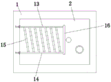
图3为定模板俯视的剖视结构示意图。FIG. 3 is a schematic cross-sectional structural diagram of a fixed template from a top view.
图中:1、底板;2、定模板;3、连接板;4、动模板;5、第一注塑腔;6、第一模仁;7、第二注塑腔;8、第二模仁;9、滑槽;10、弹簧;11、滑板;12、顶杆;13、第一冷却水腔;14、第二冷却水腔;15、第一连接腔;16、第二连接腔;17、进料孔;18、进料管。In the figure: 1. Bottom plate; 2. Fixed template; 3. Connecting plate; 4. Moving template; 5. First injection cavity; 6. First mold core; 7. Second injection cavity; 8. Second mold core; 9, chute; 10, spring; 11, slide plate; 12, ejector rod; 13, first cooling water chamber; 14, second cooling water chamber; 15, first connecting chamber; 16, second connecting chamber; 17, Feed hole; 18. Feed pipe.
具体实施方式Detailed ways
下面将结合本实用新型实施例中的附图,对本实用新型实施例中的技术方案进行清楚、完整地描述,显然,所描述的实施例仅仅是本实用新型一部分实施例,而不是全部的实施例。基于本实用新型中的实施例,本领域普通技术人员在没有做出创造性劳动前提下所获得的所有其他实施例,都属于本实用新型保护的范围。The technical solutions in the embodiments of the present utility model will be clearly and completely described below with reference to the accompanying drawings in the embodiments of the present utility model. Obviously, the described embodiments are only a part of the embodiments of the present utility model, rather than all the implementations. example. Based on the embodiments of the present invention, all other embodiments obtained by those of ordinary skill in the art without creative work fall within the protection scope of the present invention.
如图1-3所示,本实用新型提供一种技术方案:一种防触电插芯插座注塑模具,包括底板1,底板1的顶部固定安装有定模板2,定模板2的上方设有连接板3,连接板3的底部固定安装有动模板4,定模板2的顶部开设有第一注塑腔5,第一注塑腔5内固定安装有第一模仁6,动模板4的底部开设有第二注塑腔7,第二注塑腔7内固定安装有第二模仁8,第二注塑腔7与第一注塑腔5相连通,定模板2的顶部开设有四个滑槽9,四个滑槽9呈两两对称设置,四个滑槽9内均滑动安装有滑板11,四个滑板11的底部均固定安装有弹簧10,四个弹簧10的底端分别与相对应滑槽9的底部内壁固定连接,动模板4的底部固定安装有四个顶杆12,四个顶杆12呈两两对称设置,四个顶杆12分别延伸至相对应的滑槽9内,且四个顶杆12的底端分别与相对应滑板11的顶部接触,定模板2上开设有位于第一注塑腔5下方的第一冷却水腔13和第二冷却水腔14,定模板2上开设有位于第一冷却水腔13和第二冷却水腔14之间的第一连接腔15,第一冷却水腔13和第二冷却水腔14均与第一连接腔15相连通。As shown in Figures 1-3, the present invention provides a technical solution: an injection mold for an electric shock-proof ferrule socket, comprising a
定模板2上开设有位于第一注塑腔5下方的第二连接腔16,第一冷却水腔13和第二冷却水腔14均与第二连接腔16相连通,第二模仁8的顶部开设有进料孔17,连接板3的顶部固定安装有进料管18,进料管18的底端延伸至第二注塑腔7内,且进料管18与进料孔17相连通,进料管18的顶端固定连接有输料软管,定模板2的一侧固定安装有进水管和出水管,进水管与第一冷却水腔13相连通,出水管与第二冷却水腔14相连通,滑槽9的两侧内壁上均开设有限位槽,滑板11的两侧均固定安装有限位杆,限位杆滑动安装在相对应的限位槽内,第一连接腔15的数量为多个,多个第一连接腔15呈等间距排布,且多个第一连接腔15均为倾斜设置。The fixed
使用时,底板1固定安装在工作台上,连接板3的顶部与气缸活塞杆固定连接,利用气缸活塞杆可控制连接板3和动模板4的升降,在对防触电插芯插座进行注塑工作时,首先,控制动模板4向下移动,使得动模板4的底部与定模板2的顶部紧密贴合,此时四个顶杆12分别插入相对应的滑槽9内,四个顶杆12推动相对应的滑板11向下滑动,滑板11带动相对应的限位杆在相对应的限位槽内下滑,四个弹簧10受到压缩变形产生弹力,利用四个弹簧10的弹力作用,可对动模板4与定模板2合模时产生的冲击力进行有效缓冲,避免动模板4与定模板2长期受到合模时产生的冲击力而受损坏,延长动模板4与定模板2的使用寿命,第一注塑腔5和第二注塑腔7形成密封空间,使得第一模仁6和第二模仁8之间形成成型腔室,然后把注塑原料依次经过输料软管、进料管18和进料孔注入成型腔室内,从而使得成型腔室内的原料注塑成型,在注塑成型过程中,冷却水经过进水管流入第一冷却水腔13内,然后再经过多个第一连接腔15和第二连接腔16回流至第二冷却水腔14内,最后从出水管流出,从而使得冷却水进行循环流动,利用冷却水的循环流动,可对注塑成型物件中的热量进行吸收,对注塑成型的物件进行冷却降温,加快注塑成型物件的注塑成型,提高了工作效率,对注塑成型的物件冷却完毕后,控制连接板3和动模板4上升,使得动模板4与定模板2进行脱模,此时在四个弹簧10的弹力作用下,推动相对应的滑板11向上滑动,四个滑板11推动四个顶杆12、动模板4上移,从而使得动模板4与定模板2进行脱模时更加顺利,动模板4与定模板2之间不会因为粘合而打不开,提高了动模板4与定模板2的脱模效率,然后便可把成型的物件取出,同时本说明书中未作详细描述的内容均属于本领域专业技术人员公知的现有技术。When in use, the
综上可得,该一种防触电插芯插座注塑模具,通过控制动模板4向下移动,使得动模板4的底部与定模板2的顶部紧密贴合,进行合模工作,四个顶杆12分别插入相对应的滑槽9内,并分别推动相对应的滑板11向下滑动,四个弹簧10受到压缩变形产生弹力,利用四个弹簧10产生的弹力作用,可对动模板4与定模板2合模时产生的冲击力进行有效缓冲,避免动模板4与定模板2长期受到合模时产生的冲击力而受损坏,延长动模板4与定模板2的使用寿命,通过把注塑原料经过输料软管、进料管18和进料孔注入成型腔室内,从而使得第一模仁6和第二模仁8之间形成的成型腔室内的原料注塑成型,在注塑成型过程中,冷却水经过进水管流入第一冷却水腔13内,再经过多个第一连接腔15和第二连接腔16回流至第二冷却水腔14内,最后从出水管流出,从而利用冷却水的循环流动,可对注塑成型物件中的热量进行吸收,对注塑成型的物件进行冷却降温,加快了对注塑成型物件的冷却效率,提高了工作效率,通过控制连接板3和动模板4上升,使得动模板4与定模板2进行脱模,利用四个弹簧10的弹力作用下,推动相对应的滑板11向上滑动,四个滑板11推动四个顶杆12、动模板4上移,使得动模板4与定模板2进行脱模时更加顺利,动模板4与定模板2之间不会因为粘合而打不开,提高了动模板4与定模板2的脱模效率,本实用新型设计合理,实用性好,能够对动模板4与定模板2合模时产生的冲击力进行有效缓冲,避免动模板4与定模板2长期受到合模时产生的冲击力而受损坏,并且可对注塑成型的物件进行快速的冷却降温,加快物件的成型,提高了工作效率,而且便于动模板4与定模板2进行顺利脱模,方便取出成型物件。To sum up, this kind of injection mold for the anti-electric shock ferrule socket can control the moving
Claims (6)
Priority Applications (1)
| Application Number | Priority Date | Filing Date | Title |
|---|---|---|---|
| CN202020580923.XU CN211993999U (en) | 2020-04-18 | 2020-04-18 | Injection mold for anti-electric shock ferrule socket |
Applications Claiming Priority (1)
| Application Number | Priority Date | Filing Date | Title |
|---|---|---|---|
| CN202020580923.XU CN211993999U (en) | 2020-04-18 | 2020-04-18 | Injection mold for anti-electric shock ferrule socket |
Publications (1)
| Publication Number | Publication Date |
|---|---|
| CN211993999U true CN211993999U (en) | 2020-11-24 |
Family
ID=73415662
Family Applications (1)
| Application Number | Title | Priority Date | Filing Date |
|---|---|---|---|
| CN202020580923.XU Active CN211993999U (en) | 2020-04-18 | 2020-04-18 | Injection mold for anti-electric shock ferrule socket |
Country Status (1)
| Country | Link |
|---|---|
| CN (1) | CN211993999U (en) |
-
2020
- 2020-04-18 CN CN202020580923.XU patent/CN211993999U/en active Active
Similar Documents
| Publication | Publication Date | Title |
|---|---|---|
| CN210453475U (en) | Keyboard button liquid injection molding equipment | |
| CN215039753U (en) | Injection mold for plastic products convenient for rapid demoulding | |
| CN218462793U (en) | Injection mold structure with high demolding efficiency | |
| CN105172045B (en) | Mould structure | |
| CN217573943U (en) | Injection mold convenient to take off material fast | |
| CN209955187U (en) | Injection mold capable of being rapidly disassembled | |
| CN218053749U (en) | Impact Resistant Injection Mold | |
| CN216992926U (en) | Injection mold quick ejection mechanism capable of efficiently demolding | |
| CN212123881U (en) | A computer shell mold with secondary ejection | |
| CN213166614U (en) | Safe and rapid demoulding injection mold | |
| CN210999852U (en) | Plastic foam mould convenient to drawing of patterns | |
| CN218640256U (en) | Quick demoulding mould of preservation box cover | |
| CN215750506U (en) | Mould with novel structure | |
| CN217395609U (en) | Injection mold for small products | |
| CN220741996U (en) | Plastic product forming die | |
| CN219522889U (en) | Tap box bottom shell injection mold | |
| CN217414723U (en) | Low-pressure injection molding die carrier for automobile parts | |
| CN222245876U (en) | Mould for electronic component injection molding | |
| CN218462812U (en) | Plastic injection mold easy to demould | |
| CN223302138U (en) | Socket housing injection mold | |
| CN221819362U (en) | Precise injection molding device for mold | |
| CN221365658U (en) | Double-hole core-pulling die | |
| CN219004309U (en) | Cutting board die convenient to drawing of patterns | |
| CN216708186U (en) | Good mould of shaping | |
| CN222844633U (en) | Cavity structure of runner-free injection mold |
Legal Events
| Date | Code | Title | Description |
|---|---|---|---|
| GR01 | Patent grant | ||
| GR01 | Patent grant | ||
| PE01 | Entry into force of the registration of the contract for pledge of patent right | ||
| PE01 | Entry into force of the registration of the contract for pledge of patent right |
Denomination of utility model: An injection mold for anti electric shock plug socket Effective date of registration: 20211103 Granted publication date: 20201124 Pledgee: Guangdong Nanhai Rural Commercial Bank branch branch of Limited by Share Ltd. Pledgor: FOSHAN SHUNDE TIMMAS ELECTRONIC CO.,LTD. Registration number: Y2021980011868 |
|
| PC01 | Cancellation of the registration of the contract for pledge of patent right | ||
| PC01 | Cancellation of the registration of the contract for pledge of patent right |
Granted publication date: 20201124 Pledgee: Guangdong Nanhai Rural Commercial Bank branch branch of Limited by Share Ltd. Pledgor: FOSHAN SHUNDE TIMMAS ELECTRONIC CO.,LTD. Registration number: Y2021980011868 |
|
| PE01 | Entry into force of the registration of the contract for pledge of patent right | ||
| PE01 | Entry into force of the registration of the contract for pledge of patent right |
Denomination of utility model: An injection mold for anti electric shock plug socket Granted publication date: 20201124 Pledgee: Agricultural Bank of China Limited Shunde Daliang sub branch Pledgor: FOSHAN SHUNDE TIMMAS ELECTRONIC CO.,LTD. Registration number: Y2026980018356 |