CN211993873U - EPP product demolding is with ejecting structure of steam - Google Patents
EPP product demolding is with ejecting structure of steam Download PDFInfo
- Publication number
- CN211993873U CN211993873U CN202020394118.8U CN202020394118U CN211993873U CN 211993873 U CN211993873 U CN 211993873U CN 202020394118 U CN202020394118 U CN 202020394118U CN 211993873 U CN211993873 U CN 211993873U
- Authority
- CN
- China
- Prior art keywords
- steam
- steam outlet
- hole
- wall
- channel
- Prior art date
- Legal status (The legal status is an assumption and is not a legal conclusion. Google has not performed a legal analysis and makes no representation as to the accuracy of the status listed.)
- Expired - Fee Related
Links
- 238000007789 sealing Methods 0.000 claims description 7
- 230000003068 static effect Effects 0.000 claims description 5
- 238000004519 manufacturing process Methods 0.000 description 3
- 239000000463 material Substances 0.000 description 3
- 238000007493 shaping process Methods 0.000 description 3
- 230000005540 biological transmission Effects 0.000 description 2
- 238000004891 communication Methods 0.000 description 2
- 238000000034 method Methods 0.000 description 2
- 238000000926 separation method Methods 0.000 description 2
- 230000004075 alteration Effects 0.000 description 1
- 239000011324 bead Substances 0.000 description 1
- 230000009286 beneficial effect Effects 0.000 description 1
- 230000006835 compression Effects 0.000 description 1
- 238000007906 compression Methods 0.000 description 1
- 238000001816 cooling Methods 0.000 description 1
- 238000010586 diagram Methods 0.000 description 1
- 230000005484 gravity Effects 0.000 description 1
- 238000012986 modification Methods 0.000 description 1
- 230000004048 modification Effects 0.000 description 1
- 238000011084 recovery Methods 0.000 description 1
- 238000006467 substitution reaction Methods 0.000 description 1
Images


Landscapes
- Moulds For Moulding Plastics Or The Like (AREA)
Abstract
The utility model discloses a EPP product goes out mould and uses ejecting structure of steam, its technical scheme main points are: the steam mold comprises a mold core, wherein a mold cavity is formed in the middle of the upper surface of the mold core, a steam outlet is formed below the mold cavity, a steam outlet through hole is formed below the steam outlet, and the mold cavity and the steam outlet are communicated with the steam outlet through hole; a steam outlet communicating sleeve is fixedly arranged in the steam outlet through hole, a sliding block is arranged on the inner wall of the steam outlet communicating sleeve in a sliding fit manner, the upper end of the sliding block is fixedly connected with a push rod, the upper end of the push rod is in threaded connection with a top block, and the shape of the top block is matched with that of a steam outlet; the body fixed connection of mold core is in quiet die holder, and the steam passageway has been seted up to the inside of quiet die holder, and the longitudinal channel of steam passageway is linked together with the lower extreme that steam goes out vapour through-hole, and the transverse channel of steam passageway runs through quiet die holder and accesss to the external world. The utility model discloses shorten the length of push rod, utilized steam to blow off the product, shortened the drawing of patterns time of product.
Description
Technical Field
The utility model relates to an ejecting technical field of mould, in particular to EPP product goes out mould with ejecting structure of steam.
Background
EPP material specific gravity is light, elasticity is good, antidetonation resistance to compression, deformation recovery rate are high, EPP is widely used on the car, can mould into EPP products of various shapes in the mould of make-up machine with EPP bead, generally process into thin wall, lamellar, and in the mould shaping process, in order to make the product drop after shaping, usually adopt the push rod to push out the product. However, when the push rod is used for ejection, the push rod needs to have a longer stroke, and the length of the corresponding push rod is also longer, so that the demolding time is long, and the production efficiency is influenced.
SUMMERY OF THE UTILITY MODEL
To the problem mentioned in the background art, the utility model aims at providing a EPP product goes out ejecting structure of steam for the mould uses through the cooperation that sets up steam play vapour through-hole and push rod to solve the longer long problem of drawing of patterns time that leads to of the length of the push rod of mentioning in the background art.
The above technical purpose of the present invention can be achieved by the following technical solutions:
a steam ejection structure for mold stripping of an EPP product comprises a mold core, wherein a cavity is formed in the middle of the upper surface of the mold core, a steam outlet is formed below the cavity, a steam outlet through hole is formed below the steam outlet, and the cavity and the steam outlet are communicated with the steam outlet through hole; a steam outlet communicating sleeve is fixedly arranged in the steam outlet through hole, a sliding block is arranged on the inner wall of the steam outlet communicating sleeve in a sliding fit manner, the upper end of the sliding block is fixedly connected with a push rod, the upper end of the push rod is in threaded connection with a top block, and the shape of the top block is matched with that of a steam outlet; the body fixed connection of mold core is in quiet die holder, and the steam passageway has been seted up to the inside of quiet die holder, and the longitudinal channel of steam passageway is linked together with the lower extreme that steam goes out vapour through-hole, and the transverse channel of steam passageway runs through quiet die holder and accesss to the external world.
Through adopting above-mentioned technical scheme, this device is when using, high-pressure steam passes through steam channel and gets into steam play vapour through-hole, promote the slider and drive the push rod and upwards slide in a play vapour intercommunication cover, the push rod promotes the kicking block and makes kicking block and steam play steam outlet separation, the ejecting EPP product of kicking block, the length of push rod has been shortened to above structural design, high-pressure steam's transmission rate is fast, steam can follow steam outlet and blow off the EPP product simultaneously, the time of the product drawing of patterns has been shortened, and the production efficiency is improved.
Furthermore, a return spring is fixedly arranged between the inner wall of the top end of the steam outlet communicating sleeve and the sliding block.
Through above technical scheme, after the kicking block ejecting EPP product, stop letting in steam, the kicking block can move downwards with the help of reset spring's elasticity, cooperates with steam outlet again.
Furthermore, the bottom of the steam outlet communicating sleeve is tightly attached to the inner wall of the steam outlet through hole, the diameter of the outer wall of the upper part of the steam outlet communicating sleeve is smaller than that of the inner wall of the steam outlet through hole, and a steam outlet circular hole is formed in the side wall of the upper part of the steam outlet communicating sleeve.
Through above technical scheme, go out the upper portion outer wall diameter of vapour intercommunication cover and be less than the inner wall diameter that steam goes out the vapour through-hole, go out the lateral wall on vapour intercommunication cover upper portion and seted up out the vapour round hole, steam can get into steam through going out the vapour round hole and go out the vapour through-hole, then get into steam and go out the steam port to blow off the EPP product.
Furthermore, a sealing ring is fixedly arranged on the bottom surface of the mold core and the top surface of the static mold base outside the lower port of the steam outlet through hole.
Through above technical scheme, the leakproofness of steam play vapour through-hole lower extreme department can be improved to the sealing washer, avoids appearing gas leakage phenomenon.
Furthermore, the outer wall of the static die holder is fixedly provided with a steam pipe joint at an outlet of a transverse channel of the steam channel.
Through above technical scheme, steam pipe connection can connect the steam pipe, and the steam pipe is connected with external steam source, provides high-pressure steam for this device, and steam pipe connection is the pivot of this device connection power supply.
To sum up, the utility model discloses mainly have following beneficial effect:
this device is when using, and high-pressure steam passes through steam passageway and gets into steam and goes out the vapour through-hole, promotes the slider and drives the push rod upwards to slide in going out vapour intercommunication cover, and the push rod promotes the kicking block and makes kicking block and steam play steam outlet separation, and the ejecting EPP product of kicking block, above structural design has shortened the length of push rod, and high-pressure steam's transmission speed is fast, and steam can be followed steam outlet and blown EPP product down, has shortened the time of product drawing of patterns simultaneously, improves production efficiency.
Drawings
Fig. 1 is a schematic structural diagram of an embodiment of the present invention;
FIG. 2 is an enlarged view at A in FIG. 1;
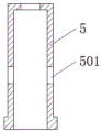
fig. 3 is a schematic structural view of the steam outlet communication sleeve in the embodiment of the present invention.
Reference numerals: 1. a mold core; 2. a cavity; 3. a steam outlet; 4. a steam outlet through hole; 5. a steam outlet communicating sleeve; 6. a slider; 7. a push rod; 8. a top block; 9. a static die holder; 10. a steam channel; 11. a return spring; 12. a seal ring; 13. a steam pipe joint; 501. and a steam outlet circular hole.
Detailed Description
In order to make the objects and technical solutions of the present invention clear and fully described, and the advantages thereof more clearly understood, the embodiments of the present invention are described in further detail below with reference to the accompanying drawings.
In the description of the present invention, it should be noted that the terms "center", "upper", "lower", "left", "right", "inner", "outer", "top", "bottom", "side", "vertical", "horizontal", and the like indicate the orientation or positional relationship based on the orientation or positional relationship shown in the drawings, and are only for convenience of description and simplification of description, but do not indicate or imply that the device or element referred to must have a specific orientation, be constructed and operated in a specific orientation, and thus, should not be construed as limiting the present invention. Furthermore, the terms "first," "second," "third," "fourth," "fifth," and "sixth" are used for descriptive purposes only and are not to be construed as indicating or implying relative importance.
In the description of the present invention, it is to be noted that, unless otherwise explicitly specified or limited, the terms "mounted," "connected," and "connected" are to be construed broadly, and may be, for example, fixedly connected, detachably connected, or integrally connected; can be mechanically or electrically connected; they may be connected directly or indirectly through intervening media, or they may be interconnected between two elements. The specific meaning of the above terms in the present invention can be understood in specific cases to those skilled in the art.
For the purposes of simplicity and explanation, the principles of the embodiments are described by referring mainly to examples. In the following description, numerous specific details are set forth in order to provide a thorough understanding of the embodiments. It will be apparent, however, to one skilled in the art that the embodiments may be practiced without these specific details. In some instances, well-known methods and structures have not been described in detail so as not to unnecessarily obscure the embodiments, and all embodiments may be used in combination with each other.
The present invention will be described in detail with reference to the accompanying drawings and examples.
Example 1
Referring to fig. 1, 2 and 3, the steam ejection structure for the mold stripping of the EPP product comprises a mold core 1, a mold cavity 2 is arranged in the middle of the upper surface of the mold core 1, a steam outlet 3 is arranged below the mold cavity 2, a steam outlet through hole 4 is arranged below the steam outlet 3, and the mold cavity 2 and the steam outlet 3 are communicated with the steam outlet through hole 4; a steam outlet communicating sleeve 5 is fixedly arranged in the steam outlet through hole 4, a sliding block 6 is arranged on the inner wall of the steam outlet communicating sleeve 5 in a sliding fit manner, a push rod 7 is fixedly connected to the upper end of the sliding block 6, the upper end of the push rod 7 is in threaded connection with a top block 8, a threaded hole is formed in the bottom of the top block 8, an external thread matched with the threaded hole of the top block 8 is arranged at the top end of the push rod 7, the shape of the top block 8 is matched with that of the steam outlet 3, and the top block 8 and the steam outlet 3 are in a conical shape with a large upper end diameter and a small lower end diameter; the body fixed connection of mold core 1 is in quiet die holder 9, and quiet die holder 9 is whole to be located the below of mold core 1, and steam channel 10 has been seted up to the inside of quiet die holder 9, and steam channel 10 is including the longitudinal channel and the transverse channel that are linked together, and the longitudinal channel of steam channel 10 is linked together with the lower extreme that steam goes out vapour through-hole 4, and the transverse channel of steam channel 10 runs through quiet die holder 9 and accesss to the external world.
Referring to fig. 1 and 2, in order to stop introducing steam after the ejector block 8 ejects the EPP product, the ejector block 8 can move downwards by means of the elastic force of the return spring 11 and is matched with the steam outlet 3 again, so that the molten EPP material can be cooled and molded in the cavity 2, and the return spring 11 is fixedly arranged between the inner wall of the top end of the steam outlet communication sleeve 5 and the sliding block 6.
Referring to fig. 2 and 3, in order to allow steam to enter the steam outlet through hole 4 through the steam outlet circular hole 501 and then enter the steam outlet 3, so as to blow off the EPP product, the bottom of the steam outlet communicating sleeve 5 is closely attached to the inner wall of the steam outlet through hole 4, the diameter of the outer wall of the upper part of the steam outlet communicating sleeve 5 is smaller than that of the inner wall of the steam outlet through hole 4, and the steam outlet circular hole 501 is formed in the side wall of the upper part of the steam outlet communicating sleeve 5.
Referring to fig. 1, in order to improve the tightness of the lower end of the steam outlet through hole 4 and avoid the occurrence of air leakage, the bottom surface of the mold core 1 and the top surface of the stationary mold base 9 are fixedly provided with a sealing ring 12 outside the lower end of the steam outlet through hole 4, the sealing ring 12 is made of high temperature resistant rubber material, and the sealing ring is good in sealing performance and durable.
Referring to fig. 1, in order to connect a steam pipe to the device, the steam pipe is connected with an external steam source to provide high-pressure steam for the device, a steam pipe joint 13 is fixedly arranged on the outer wall of the stationary die holder 9 at an outlet of a transverse channel of the steam channel 10, and the steam pipe joint 13 is a pivot for connecting the device with a power source.
The working principle is as follows: this device is when using, the outside steam source provides high-pressure steam, steam gets into steam channel 10 through the steam pipe that steam pipe joint 13 connects, steam gets into out vapour communicating sleeve 5 by steam channel 10 again, steam promotes out the inside slider 6 of vapour communicating sleeve 5 and drives push rod 7 and kicking block 8 rebound, then ejecting cooling shaping EPP product, when slider 6 removed the top of a vapour round hole 501, steam got into steam by a vapour round hole 501 and goes out vapour through-hole 4, then got into communicating steam play vapour mouth 3 and blown off the EPP product, the time of the product drawing of patterns has been shortened.
Although embodiments of the present invention have been shown and described, it will be appreciated by those skilled in the art that changes, modifications, substitutions and alterations can be made in these embodiments without departing from the principles and spirit of the invention, the scope of which is defined in the appended claims and their equivalents.
Claims (5)
1. The utility model provides a EPP product demolding is with ejecting structure of steam, includes mold core (1), its characterized in that: a cavity (2) is formed in the middle of the upper surface of the mold core (1), a steam outlet (3) is formed below the cavity (2), a steam outlet through hole (4) is formed below the steam outlet (3), and the cavity (2) and the steam outlet (3) are communicated with the steam outlet through hole (4); a steam outlet communicating sleeve (5) is fixedly arranged in the steam outlet through hole (4), a sliding block (6) is arranged on the inner wall of the steam outlet communicating sleeve (5) in a sliding fit manner, a push rod (7) is fixedly connected to the upper end of the sliding block (6), an ejector block (8) is in threaded connection with the upper end of the push rod (7), and the shape of the ejector block (8) is matched with that of the steam outlet (3); the body fixed connection of mold core (1) is in quiet die holder (9), steam channel (10) have been seted up to the inside of quiet die holder (9), the longitudinal channel of steam channel (10) with the lower extreme of steam play vapour through-hole (4) is linked together, the transverse channel of steam channel (10) runs through quiet die holder (9) accesss to the external world.
2. The steam ejection structure for EPP product demolding according to claim 1, wherein: and a return spring (11) is fixedly arranged between the inner wall of the top end of the steam outlet communicating sleeve (5) and the sliding block (6).
3. The steam ejection structure for EPP product demolding according to claim 1, wherein: the bottom of the steam outlet communicating sleeve (5) is tightly attached to the inner wall of the steam outlet through hole (4), the diameter of the outer wall of the upper portion of the steam outlet communicating sleeve (5) is smaller than that of the inner wall of the steam outlet through hole (4), and a steam outlet circular hole (501) is formed in the side wall of the upper portion of the steam outlet communicating sleeve (5).
4. The steam ejection structure for EPP product demolding according to claim 1, wherein: and a sealing ring (12) is fixedly arranged on the bottom surface of the mold core (1) and the top surface of the static mold base (9) at the outer side of the lower port of the steam outlet through hole (4).
5. The steam ejection structure for EPP product demolding according to claim 1, wherein: and a steam pipe joint (13) is fixedly arranged on the outer wall of the static die holder (9) at the outlet of the transverse channel of the steam channel (10).
Priority Applications (1)
| Application Number | Priority Date | Filing Date | Title |
|---|---|---|---|
| CN202020394118.8U CN211993873U (en) | 2020-03-25 | 2020-03-25 | EPP product demolding is with ejecting structure of steam |
Applications Claiming Priority (1)
| Application Number | Priority Date | Filing Date | Title |
|---|---|---|---|
| CN202020394118.8U CN211993873U (en) | 2020-03-25 | 2020-03-25 | EPP product demolding is with ejecting structure of steam |
Publications (1)
| Publication Number | Publication Date |
|---|---|
| CN211993873U true CN211993873U (en) | 2020-11-24 |
Family
ID=73431302
Family Applications (1)
| Application Number | Title | Priority Date | Filing Date |
|---|---|---|---|
| CN202020394118.8U Expired - Fee Related CN211993873U (en) | 2020-03-25 | 2020-03-25 | EPP product demolding is with ejecting structure of steam |
Country Status (1)
| Country | Link |
|---|---|
| CN (1) | CN211993873U (en) |
Cited By (1)
| Publication number | Priority date | Publication date | Assignee | Title |
|---|---|---|---|---|
| CN116765326A (en) * | 2023-06-29 | 2023-09-19 | 洛阳科品钛业股份有限公司 | Titanium alloy deep cylindrical casting self-releasing metal mold |
-
2020
- 2020-03-25 CN CN202020394118.8U patent/CN211993873U/en not_active Expired - Fee Related
Cited By (2)
| Publication number | Priority date | Publication date | Assignee | Title |
|---|---|---|---|---|
| CN116765326A (en) * | 2023-06-29 | 2023-09-19 | 洛阳科品钛业股份有限公司 | Titanium alloy deep cylindrical casting self-releasing metal mold |
| CN116765326B (en) * | 2023-06-29 | 2025-07-29 | 洛阳科品钛业股份有限公司 | Self-demoulding metal mould for titanium alloy deep cylindrical casting |
Similar Documents
| Publication | Publication Date | Title |
|---|---|---|
| CN102107523B (en) | Horizontal type blow molding die for automobile oil tube and blow molding method thereof | |
| CN109159384B (en) | No weld mark injection structure of accurate car grid mould | |
| CN112248389A (en) | Injection mold for producing high-strength accessories | |
| CN202344743U (en) | Mold structure of bottle cap compression molding machine | |
| CN213006408U (en) | Auto-parts injection mold convenient to drawing of patterns | |
| CN209971510U (en) | Toothpaste tube production gas blowing device | |
| CN108568960B (en) | Vapour-pressure type mould of drawing of patterns of being convenient for | |
| CN210733113U (en) | Tubular cavity injection mold | |
| CN209699786U (en) | A kind of ejecting mechanism of plastics injection mould | |
| CN217434875U (en) | High temperature mould inner insert injection moulding mould | |
| CN114918400B (en) | Mould for rack lock convenient to drawing of patterns | |
| CN214872310U (en) | Plastic part injection molding cooling mold | |
| CN206598469U (en) | A kind of injection mould | |
| CN205871070U (en) | Plastic mold for automotive interior | |
| CN202895672U (en) | Air-blowing pre-ventilating device for injection blow hollow molding machine | |
| CN210940080U (en) | Smooth and easy semiconductor plastic envelope mould of exhaust | |
| CN210820610U (en) | High-speed injection mold | |
| CN211917673U (en) | Plastic hollow body blow molding system | |
| CN210553225U (en) | Portable demoulding structure of hardware mould | |
| CN213944585U (en) | One-die two-piece forming die based on heat shield production | |
| CN209580448U (en) | A kind of Cavity blow mold | |
| CN219114700U (en) | Blowing device of mold demolding mechanism | |
| CN209616263U (en) | A kind of ejecting structure of injection mold | |
| CN210634044U (en) | Ejection mechanism of mold | |
| CN216442956U (en) | A forming mold for plastic shell production |
Legal Events
| Date | Code | Title | Description |
|---|---|---|---|
| GR01 | Patent grant | ||
| GR01 | Patent grant | ||
| CF01 | Termination of patent right due to non-payment of annual fee |
Granted publication date: 20201124 |
|
| CF01 | Termination of patent right due to non-payment of annual fee |