CN211990819U - a new mold - Google Patents
a new mold Download PDFInfo
- Publication number
- CN211990819U CN211990819U CN202020287555.XU CN202020287555U CN211990819U CN 211990819 U CN211990819 U CN 211990819U CN 202020287555 U CN202020287555 U CN 202020287555U CN 211990819 U CN211990819 U CN 211990819U
- Authority
- CN
- China
- Prior art keywords
- mold
- fixedly connected
- positioning seat
- cushion block
- gear
- Prior art date
- Legal status (The legal status is an assumption and is not a legal conclusion. Google has not performed a legal analysis and makes no representation as to the accuracy of the status listed.)
- Active
Links
- 230000005540 biological transmission Effects 0.000 claims abstract description 17
- 230000008878 coupling Effects 0.000 claims abstract description 9
- 238000010168 coupling process Methods 0.000 claims abstract description 9
- 238000005859 coupling reaction Methods 0.000 claims abstract description 9
- 239000000463 material Substances 0.000 abstract description 9
- 238000010521 absorption reaction Methods 0.000 abstract description 5
- 230000035939 shock Effects 0.000 abstract description 5
- 238000003825 pressing Methods 0.000 abstract description 3
- 238000000034 method Methods 0.000 description 12
- 230000008569 process Effects 0.000 description 10
- 238000004519 manufacturing process Methods 0.000 description 5
- 230000003139 buffering effect Effects 0.000 description 4
- 230000007704 transition Effects 0.000 description 4
- 238000012986 modification Methods 0.000 description 3
- 230000004048 modification Effects 0.000 description 3
- 238000010586 diagram Methods 0.000 description 2
- 238000000465 moulding Methods 0.000 description 2
- 239000000243 solution Substances 0.000 description 2
- 238000003723 Smelting Methods 0.000 description 1
- 230000009286 beneficial effect Effects 0.000 description 1
- 238000000071 blow moulding Methods 0.000 description 1
- 238000004891 communication Methods 0.000 description 1
- 230000006835 compression Effects 0.000 description 1
- 238000007906 compression Methods 0.000 description 1
- 230000007812 deficiency Effects 0.000 description 1
- 238000004512 die casting Methods 0.000 description 1
- 230000000694 effects Effects 0.000 description 1
- 238000005516 engineering process Methods 0.000 description 1
- 238000002474 experimental method Methods 0.000 description 1
- 238000001125 extrusion Methods 0.000 description 1
- 238000005242 forging Methods 0.000 description 1
- 238000009776 industrial production Methods 0.000 description 1
- 238000001746 injection moulding Methods 0.000 description 1
- 238000012545 processing Methods 0.000 description 1
- 239000002699 waste material Substances 0.000 description 1
Images

Landscapes
- Moulds For Moulding Plastics Or The Like (AREA)
Abstract
本实用新型公开了一种新型模具,属于模具技术领域,所述新型模具包括上模座以及下模座,所述上模座左侧固定连接有齿条,所述齿条左侧啮合连接有齿轮,所述齿轮上固定连接有旋转轴,所述旋转轴下端通过联轴器传动连接有传动轴,所述传动轴动力输入端与电机动力输出端相连接,所述下模座上端固定连接有定位座,所述定位座内壁底部固定连接有垫块A。本实用新型中,当定位柱进入定位座内部凹槽中时,会对垫块B产生挤压力,与底部的垫块A从而压迫下方所衔接的弹簧进行压缩,弹簧收缩从而起到一定缓冲减震作用,采用自动化设备将合模后的模具进行分离,方便工作人员取料,适合被广泛推广和使用。

The utility model discloses a novel mold, belonging to the technical field of molds. The novel mold comprises an upper mold base and a lower mold base. A rack is fixedly connected to the left side of the upper mold base, and a gear rack is meshed and connected to the left side of the rack. Gear, a rotating shaft is fixedly connected to the gear, the lower end of the rotating shaft is connected to a transmission shaft through a coupling, the power input end of the transmission shaft is connected to the power output end of the motor, and the upper end of the lower die base is fixedly connected There is a positioning seat, and a cushion block A is fixedly connected to the bottom of the inner wall of the positioning seat. In the utility model, when the positioning column enters the inner groove of the positioning seat, it will produce a pressing force on the cushion block B, and the cushion block A at the bottom will press the spring connected below to compress, and the spring will shrink to play a certain buffer. Shock absorption, the use of automatic equipment to separate the mold after clamping, convenient for the staff to take materials, suitable for widespread promotion and use.
Description
技术领域technical field
本实用新型涉及模具技术领域,尤其涉及一种新型模具。The utility model relates to the technical field of molds, in particular to a novel mold.
背景技术Background technique
模具,工业生产上用以注塑、吹塑、挤出、压铸或锻压成型、冶炼、冲压等方法得到所需产品的各种模子和工具。 简而言之,模具是用来制作成型物品的工具,这种工具由各种零件构成,不同的模具由不同的零件构成。它主要通过所成型材料物理状态的改变来实现物品外形的加工。素有“工业之母”的称号。Molds, various molds and tools used in industrial production to obtain the desired products by injection molding, blow molding, extrusion, die casting or forging, smelting, stamping and other methods. In a nutshell, a mold is a tool used to make a shaped item, this tool is made up of various parts, and different molds are made up of different parts. It mainly realizes the processing of the shape of the article by changing the physical state of the formed material. Known as the "Mother of Industry".
专利号CN201820472354.X公布了一种模具,有助于在内浇道包括多个与成型腔连通的分支浇道时减少废料。本实用新型的模具包括彼此层叠的第一模具和第二模具,且具有与外部连通的直浇道、与所述直浇道连通的横浇道以及经由过渡部与所述横浇道连通的内浇道,该内浇道包括沿所述第一模具和所述第二模具的层叠方向延伸的多个分支浇道,这多个分支浇道从所述过渡部分岔出,且与成型腔连通,所述第一模具与所述第二模具配合形成所述过渡部,所述第二模具形成所述多个分支浇道,其中,所述第一模具具有朝向所述第二模具突出的突起部,所述第二模具具有供所述突起部嵌入的凹陷部,所述突起部与所述凹陷部配合形成所述过渡部。Patent No. CN201820472354.X discloses a mold that helps reduce waste when an inner runner includes a plurality of branch runners that communicate with a molding cavity. The mold of the present invention includes a first mold and a second mold stacked on each other, and has a sprue communicating with the outside, a runner communicating with the sprue, and a runner communicating with the runner via a transition portion The runner includes a plurality of branch runners extending along the stacking direction of the first mold and the second mold, the plurality of branch runners branching out from the transition portion and being connected to the molding cavity communication, the first mold cooperates with the second mold to form the transition portion, and the second mold forms the plurality of branch runners, wherein the first mold has a protrusion protruding toward the second mold A protruding part, the second mold has a concave part into which the protruding part is embedded, and the protruding part cooperates with the concave part to form the transition part.
目前,上述专利所公布的模具在技术上存在一定不足:1、以往模具合模过程接触震动较大的问题;2、以往模具不易取料的问题。At present, the molds disclosed in the above-mentioned patents have certain technical deficiencies: 1. In the past, the contact vibration of the mold during the mold clamping process was relatively large; 2. In the past, the mold was not easy to take materials.
发明内容SUMMARY OF THE INVENTION
本实用新型提供一种新型模具,当定位柱进入定位座内部凹槽中时,会对垫块B产生挤压力,与底部的垫块A从而压迫下方所衔接的弹簧进行压缩,弹簧收缩从而起到一定缓冲减震作用,采用自动化设备将合模后的模具进行分离,方便工作人员取料,可以有效解决背景技术中的问题。The utility model provides a new type of mold. When the positioning column enters the inner groove of the positioning seat, a pressing force will be generated on the cushion block B, and the cushion block A at the bottom will press the spring connected below to compress, and the spring will shrink to It plays a certain role of buffering and shock absorption, and adopts automatic equipment to separate the molds after mold closing, which is convenient for workers to take materials, and can effectively solve the problems in the background technology.
本实用新型提供的具体技术方案如下:The concrete technical scheme that the utility model provides is as follows:
本实用新型提供的一种新型模具,包括上模座以及下模座,所述上模座左侧固定连接有齿条,所述齿条左侧啮合连接有齿轮,所述齿轮上固定连接有旋转轴,所述旋转轴下端通过联轴器传动连接有传动轴,所述传动轴动力输入端与电机动力输出端相连接,所述下模座上端固定连接有定位座,所述定位座内壁底部固定连接有垫块A,所述垫块A上端弹性连接有垫块B,所述垫块B两侧衔接有滑块,所述定位座内侧壁开设有滑槽,所述滑槽内部滑动连接有滑块。A new type of mold provided by the utility model includes an upper mold base and a lower mold base, a rack is fixedly connected to the left side of the upper mold base, a gear is meshed and connected to the left side of the rack, and a gear is fixedly connected to the gear. A rotating shaft, the lower end of the rotating shaft is connected with a transmission shaft through a coupling, the power input end of the transmission shaft is connected with the power output end of the motor, the upper end of the lower die base is fixedly connected with a positioning seat, and the inner wall of the positioning seat is The bottom is fixedly connected with a pad A, the upper end of the pad A is elastically connected with a pad B, the two sides of the pad B are connected with a slider, the inner side wall of the positioning seat is provided with a chute, and the inner side of the chute slides A slider is attached.
可选的,所述上模座下表面固定连接有上模板。Optionally, an upper template is fixedly connected to the lower surface of the upper mold base.
可选的,所述下模座上表面固定连接有下模板。Optionally, a lower template is fixedly connected to the upper surface of the lower mold base.
可选的,所述上模座下端衔接有定位柱。Optionally, a positioning column is connected to the lower end of the upper die base.
可选的,所述上模板下表面开设有段差凹槽。Optionally, a level difference groove is formed on the lower surface of the upper template.
本实用新型的有益效果如下:The beneficial effects of the present utility model are as follows:
1、本实用新型实用,上模板通过与下模板进行合模,从而生产出模具所需要的工件,定位柱与定位座配合,在合模过程中定位柱插入定位座上孔内部,从而使得上模板与下模板进行完全契合,避免出现合模误差,当定位柱进入定位座内部凹槽中时,会对垫块B产生挤压力,与底部的垫块A从而压迫下方所衔接的弹簧进行压缩,弹簧收缩从而起到一定缓冲减震作用,解决了以往模具合模过程接触震动较大的问题。1. The utility model is practical, the upper template is clamped with the lower template to produce the workpiece required by the mold, the positioning column is matched with the positioning seat, and the positioning column is inserted into the upper hole of the positioning seat during the mold clamping process, so that the upper The template and the lower template are completely fitted to avoid mold clamping errors. When the positioning column enters the internal groove of the positioning seat, it will produce a squeezing force on the pad B, which will press the spring connected to the bottom with the pad A at the bottom. Compression, the spring shrinks to play a certain role in buffering and shock absorption, which solves the problem of large contact vibration in the previous mold clamping process.
2、本实用新型中,生产完成后,电机接通外部电源工作,然后电机带动传动轴进行转动,传动轴通过联轴器带动旋转轴进行转动,齿轮随之旋转,通过与齿条间的啮合作用从而将齿轮自身旋转运动转换为齿条的直线运动,继而将合模后的模具进行分离,方便工作人员取料,解决了以往模具不易取料的问题。2. In the present utility model, after the production is completed, the motor is connected to the external power supply to work, and then the motor drives the transmission shaft to rotate, the transmission shaft drives the rotation shaft to rotate through the coupling, and the gear rotates accordingly. It can convert the rotary motion of the gear itself into the linear motion of the rack, and then separate the mold after clamping, which is convenient for the staff to take the material, and solves the problem that the mold is not easy to take the material in the past.
附图说明Description of drawings
为了更清楚地说明本实用新型实施例中的技术方案,下面将对实施例描述中所需要使用的附图作简单地介绍,显而易见地,下面描述中的附图仅仅是本实用新型的一些实施例,对于本领域普通技术人员来讲,在不付出创造性劳动的前提下,还可以根据这些附图获得其他的附图。In order to illustrate the technical solutions in the embodiments of the present invention more clearly, the following briefly introduces the accompanying drawings used in the description of the embodiments. Obviously, the drawings in the following description are only some implementations of the present invention. For example, for those of ordinary skill in the art, other drawings can also be obtained based on these drawings without any creative effort.
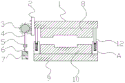
图1为本实用新型实施例的一种新型模具的整体结构示意图;1 is a schematic diagram of the overall structure of a novel mold according to an embodiment of the present utility model;
图2为本实用新型实施例的一种新型模具的上模板结构示意图;2 is a schematic structural diagram of an upper template of a novel mold according to an embodiment of the present utility model;
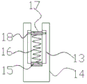
图3为本实用新型实施例的一种新型模具的A处结构示意图;Fig. 3 is the structural representation of the A place of a kind of novel mold of the utility model embodiment;
图中:1、上模座;2、齿条;3、齿轮;4、旋转轴;5、联轴器;6、传动轴;7、电机;8、上模板;9、下模座;10、下模板;11、段差凹槽;12、定位柱;13、滑槽;14、定位座;15、垫块A;16、弹簧;17、垫块B;18、滑块。In the figure: 1. Upper die base; 2. Rack; 3. Gear; 4. Rotating shaft; 5. Coupling; 6. Transmission shaft; 7. Motor; 8. Upper template; 9. Lower die base; 10 , lower template; 11, step groove; 12, positioning column; 13, chute; 14, positioning seat; 15, pad A; 16, spring; 17, pad B; 18, slider.
具体实施方式Detailed ways
为了使本实用新型的目的、技术方案和优点更加清楚,下面将结合附图对本实用新型作进一步地详细描述,显然,所描述的实施例仅是本实用新型一部分实施例,而不是全部的实施例。基于本实用新型中的实施例,本领域普通技术人员在没有做出创造性劳动前提下所获得的所有其它实施例,都属于本实用新型保护的范围。In order to make the purpose, technical solutions and advantages of the present utility model clearer, the present utility model will be described in further detail below in conjunction with the accompanying drawings. Obviously, the described embodiments are only a part of the present utility model, rather than all the implementations. example. Based on the embodiments of the present invention, all other embodiments obtained by those of ordinary skill in the art without creative work fall within the protection scope of the present invention.
下面将结合图1~图3,对本实用新型实施例的一种新型模具进行详细的说明。A new type of mold according to an embodiment of the present invention will be described in detail below with reference to FIGS. 1 to 3 .
如图1-3所示,一种新型模具,包括上模座1以及下模座9,所述上模座1左侧固定连接有齿条2,所述齿条2左侧啮合连接有齿轮3,所述齿轮3上固定连接有旋转轴4,所述旋转轴4下端通过联轴器5传动连接有传动轴6,所述传动轴6动力输入端与电机7动力输出端相连接,所述下模座9上端固定连接有定位座14,所述定位座14内壁底部固定连接有垫块A15,所述垫块A15上端弹性连接有垫块B17,所述垫块B17两侧衔接有滑块18,所述定位座14内侧壁开设有滑槽13,所述滑槽13内部滑动连接有滑块18。As shown in Figures 1-3, a new type of mold includes an upper die base 1 and a lower die base 9, the left side of the upper die base 1 is fixedly connected with a rack 2, and the left side of the rack 2 is meshed with gears 3. A rotating shaft 4 is fixedly connected to the gear 3, the lower end of the rotating shaft 4 is connected to a transmission shaft 6 through a coupling 5, and the power input end of the transmission shaft 6 is connected with the power output end of the motor 7, so A
本实施例中如图1-3所示,上模板8通过与下模板10进行合模,从而生产出模具所需要的工件,定位柱12与定位座14配合,在合模过程中定位柱12插入定位座14上孔内部,从而使得上模板8与下模板10进行完全契合,避免出现合模误差,当定位柱12进入定位座14内部凹槽中时,会对垫块B17产生挤压力,与底部的垫块A15从而压迫下方所衔接的弹簧16进行压缩,弹簧16收缩从而起到一定缓冲减震作用,解决了以往模具合模过程接触震动较大的问题;生产完成后,电机7接通外部电源工作,然后电机7带动传动轴6进行转动,传动轴6通过联轴器5带动旋转轴4进行转动,齿轮2随之旋转,通过与齿条2间的啮合作用从而将齿轮3自身旋转运动转换为齿条2的直线运动,继而将合模后的模具进行分离,方便工作人员取料,解决了以往模具不易取料的问题。In this embodiment, as shown in FIGS. 1-3 , the
其中,所述上模座1下表面固定连接有上模板8。Wherein, an
本实施例中如图1所示,上模板8通过与下模板10进行合模,从而生产出模具所需要的工件。In this embodiment, as shown in FIG. 1 , the
其中,所述下模座9上表面固定连接有下模板10。Wherein, a
本实施例中如图1所示,下模板10通过与上模板8进行合模,从而生产出模具所需要的工件。In this embodiment, as shown in FIG. 1 , the
其中,所述上模座1下端衔接有定位柱12。Wherein, the lower end of the upper die base 1 is connected with a
本实施例中如图1所示,定位柱12与定位座14配合,在合模过程中定位柱12插入定位座14上孔内部,从而使得上模板8与下模板10进行完全契合,避免出现合模误差。In this embodiment, as shown in FIG. 1 , the
其中,所述上模板8下表面开设有段差凹槽11。Wherein, the lower surface of the
本实施例中如图2所示,段差凹槽11可以减少合模过程中上模与下模整体碰撞面积,从而减少生产噪音。In this embodiment, as shown in FIG. 2 , the
需要说明的是,本实用新型为一种新型模具,工作时,上模板8通过与下模板10进行合模,从而生产出模具所需要的工件,定位柱12与定位座14配合,在合模过程中定位柱12插入定位座14上孔内部,从而使得上模板8与下模板10进行完全契合,避免出现合模误差,当定位柱12进入定位座14内部凹槽中时,会对垫块B17产生挤压力,与底部的垫块A15从而压迫下方所衔接的弹簧16进行压缩,弹簧16收缩从而起到一定缓冲减震作用,解决了以往模具合模过程接触震动较大的问题;生产完成后,电机7接通外部电源工作,然后电机7带动传动轴6进行转动,传动轴6通过联轴器5带动旋转轴4进行转动,齿轮2随之旋转,通过与齿条2间的啮合作用从而将齿轮3自身旋转运动转换为齿条2的直线运动,继而将合模后的模具进行分离,方便工作人员取料,解决了以往模具不易取料的问题;此外,段差凹槽11可以减少合模过程中上模与下模整体碰撞面积,从而减少生产噪音。所述元器件具体的型号为IDZ2065-8AE02-2电机。It should be noted that the present invention is a new type of mold. During operation, the
本实用新型的上模座1;齿条2;齿轮3;旋转轴4;联轴器5;传动轴6;电机7;上模板8;下模座9;下模板10;段差凹槽11;定位柱12;滑槽13;定位座14;垫块A15;弹簧16;垫块B17;滑块18部件均为通用标准件或本领域技术人员知晓的部件,其结构和原理都为本技术人员均可通过技术手册得知或通过常规实验方法获知。The utility model has an upper die holder 1; a rack 2; a gear 3; a rotating shaft 4; a coupling 5; a transmission shaft 6; a motor 7; an
显然,本领域的技术人员可以对本实用新型实施例进行各种改动和变型而不脱离本实用新型实施例的精神和范围。这样,倘若本实用新型实施例的这些修改和变型属于本实用新型权利要求及其等同技术的范围之内,则本实用新型也意图包含这些改动和变型在内。Obviously, those skilled in the art can make various changes and modifications to the embodiments of the present invention without departing from the spirit and scope of the embodiments of the present invention. In this way, if these modifications and variations of the embodiments of the present utility model fall within the scope of the claims of the present utility model and their equivalents, the present utility model is also intended to include these modifications and variations.
Claims (5)
Priority Applications (1)
| Application Number | Priority Date | Filing Date | Title |
|---|---|---|---|
| CN202020287555.XU CN211990819U (en) | 2020-03-10 | 2020-03-10 | a new mold |
Applications Claiming Priority (1)
| Application Number | Priority Date | Filing Date | Title |
|---|---|---|---|
| CN202020287555.XU CN211990819U (en) | 2020-03-10 | 2020-03-10 | a new mold |
Publications (1)
| Publication Number | Publication Date |
|---|---|
| CN211990819U true CN211990819U (en) | 2020-11-24 |
Family
ID=73433042
Family Applications (1)
| Application Number | Title | Priority Date | Filing Date |
|---|---|---|---|
| CN202020287555.XU Active CN211990819U (en) | 2020-03-10 | 2020-03-10 | a new mold |
Country Status (1)
| Country | Link |
|---|---|
| CN (1) | CN211990819U (en) |
Cited By (1)
| Publication number | Priority date | Publication date | Assignee | Title |
|---|---|---|---|---|
| CN112548066A (en) * | 2020-12-12 | 2021-03-26 | 靖江市钜顺精密轻合金成型科技有限公司 | Prevent die casting die that slider moves backward |
-
2020
- 2020-03-10 CN CN202020287555.XU patent/CN211990819U/en active Active
Cited By (1)
| Publication number | Priority date | Publication date | Assignee | Title |
|---|---|---|---|---|
| CN112548066A (en) * | 2020-12-12 | 2021-03-26 | 靖江市钜顺精密轻合金成型科技有限公司 | Prevent die casting die that slider moves backward |
Similar Documents
| Publication | Publication Date | Title |
|---|---|---|
| CN217454717U (en) | Novel plastic toy injection mold | |
| CN206967877U (en) | A kind of rotary injection mold | |
| CN210969634U (en) | Mould for plastic processing convenient to get material | |
| CN215092661U (en) | A rapid grinding mechanism for mold surface finish machining | |
| CN212021367U (en) | Mould structure convenient for demoulding | |
| CN213767364U (en) | Novel positioning mechanism for die | |
| CN209869246U (en) | Three-dimensional embedded type die | |
| CN208116685U (en) | A rapid prototyping precision mold | |
| CN210940238U (en) | Mould with antiseized mould function | |
| CN210789199U (en) | Quick demoulding's mould | |
| CN207448948U (en) | A kind of cover injection mold | |
| CN217752936U (en) | Press split type mould of material shaping | |
| CN222199988U (en) | Grinding device is used in mould production | |
| CN221968391U (en) | A new type of ceramic wine bottle mold | |
| CN206839040U (en) | A kind of hard alloy mould | |
| CN207642181U (en) | A kind of automobile die processing demoulding mechanism | |
| CN219095642U (en) | Multifunctional plastic die | |
| CN206326807U (en) | A kind of pressure injection mold of wood plastics tray | |
| CN213829980U (en) | Thin-wall plastic part forming die | |
| CN222645102U (en) | Auxiliary docking type foam mold assembly frame | |
| CN212598700U (en) | Template with novel assembly mechanism | |
| CN218555498U (en) | Valve aluminum die easy to demould | |
| CN216544548U (en) | Injection mold convenient for demolding | |
| CN220637578U (en) | Mould processing platform | |
| CN212045543U (en) | Vaulting pole improved generation resin forming die |
Legal Events
| Date | Code | Title | Description |
|---|---|---|---|
| GR01 | Patent grant | ||
| GR01 | Patent grant |