CN211984452U - Drawer type shoe cabinet - Google Patents
Drawer type shoe cabinet Download PDFInfo
- Publication number
- CN211984452U CN211984452U CN202020023031.XU CN202020023031U CN211984452U CN 211984452 U CN211984452 U CN 211984452U CN 202020023031 U CN202020023031 U CN 202020023031U CN 211984452 U CN211984452 U CN 211984452U
- Authority
- CN
- China
- Prior art keywords
- shoe
- shoe box
- drawer
- type
- cabinet body
- Prior art date
- Legal status (The legal status is an assumption and is not a legal conclusion. Google has not performed a legal analysis and makes no representation as to the accuracy of the status listed.)
- Active
Links
Images


Landscapes
- Apparatus For Disinfection Or Sterilisation (AREA)
Abstract
本实用新型提供一种抽屉式鞋柜,包括柜体,柜体下端面四角位置处设置有万向轮;柜体内通过横隔板分为上腔室和下腔室,下腔室内设置有控制系统;上腔室内通过竖隔板分为前腔室和后腔室,后腔室内设置有换气风扇;前腔室内部通过隔板被分为多个鞋盒架,各鞋盒架内上侧均固定设置有紫外线杀菌灯、远红外加热器和臭氧发生器;各鞋盒架内设置有相适配的抽屉式可抽拉鞋盒;换气风扇、紫外线杀菌灯、远红外加热器、臭氧发生器以及多个总控制按钮均与控制系统电性连接。本实用新型结构简单、实用性强,可单独对不同的鞋盒进行烘干除臭干燥等处理,减少鞋柜使用产生的能耗。
The utility model provides a drawer type shoe cabinet, which comprises a cabinet body, universal wheels are arranged at the four corners of the lower end face of the cabinet body; system; the upper chamber is divided into a front chamber and a rear chamber by a vertical partition, and a ventilation fan is arranged in the rear chamber; the interior of the front chamber is divided into a plurality of shoebox racks by The sides are fixedly provided with ultraviolet germicidal lamps, far-infrared heaters and ozone generators; each shoe box rack is provided with a matching drawer-type pull-out shoe box; ventilation fans, ultraviolet germicidal lamps, far-infrared heaters, The ozone generator and a plurality of master control buttons are all electrically connected with the control system. The utility model has the advantages of simple structure and strong practicability, and can be used for drying, deodorizing, drying and other treatments for different shoe boxes independently, thereby reducing the energy consumption generated by the use of the shoe cabinets.
Description
技术领域technical field
本实用新型涉及鞋柜技术领域,具体涉及一种抽屉式鞋柜。The utility model relates to the technical field of shoe cabinets, in particular to a drawer type shoe cabinet.
背景技术Background technique
鞋柜的主要用途是来陈列闲置的鞋,随着社会的进步和人类生活水平的提高,从早期的木鞋柜演变成现在多种多样款式和制材的鞋柜,包括:木质鞋柜、电子鞋柜、消毒鞋柜等等,功能和款式各不相同。The main purpose of the shoe cabinet is to display idle shoes. With the progress of society and the improvement of human living standards, it has evolved from the early wooden shoe cabinet to the shoe cabinet of various styles and materials, including: wooden shoe cabinet, Electronic shoe cabinets, disinfection shoe cabinets, etc., have different functions and styles.
然而,现有的鞋柜大都比较笨重,当需要晾晒鞋子时,只能慢慢从鞋柜内一双一双的取出鞋子,当需要清理或晾晒鞋柜时,移动鞋柜很不方便,给人们的生活带来极大的不便。且目前的鞋盒多为一体式的收纳盒形式,鞋子放置在收纳盒内通过盖子形成密闭环境,虽然不容易积灰,但是密闭不透气容易滋生细菌。However, most of the existing shoe cabinets are relatively bulky. When the shoes need to be dried, the shoes can only be slowly taken out one by one from the shoe cabinet. When the shoe cabinet needs to be cleaned or dried, it is very inconvenient to move the shoe cabinet. Life brings great inconvenience. And most of the current shoe boxes are in the form of an integrated storage box. The shoes are placed in the storage box to form a closed environment through the cover. Although it is not easy to accumulate dust, the airtight airtightness is easy to breed bacteria.
另外在梅雨季节或者当人运动后,鞋难于干燥、鞋内具有潮湿的感觉,人们家中的鞋消毒都是露天晾晒,利用太阳的紫外线照射消毒,但是这种消毒方式容易受天气影响,特别是雨天、雪天和阴天。即便是晴天,人们也不一定有时间去晾晒鞋In addition, in the rainy season or after exercising, the shoes are difficult to dry, and the shoes have a damp feeling. People’s shoes are sterilized in the open air, and the ultraviolet rays of the sun are used to sterilize them. However, this method of sterilization is easily affected by the weather, especially Rainy, snowy and cloudy days. Even on sunny days, people don't necessarily have time to dry their shoes
实用新型内容Utility model content
为了解决现有技术中存在的缺陷,本实用新型提供一种可通风干燥、消毒除菌、除尘除臭的可移动抽屉式鞋柜。In order to solve the defects existing in the prior art, the utility model provides a movable drawer type shoe cabinet which can be ventilated and dried, disinfected and sterilized, and dust-removed and deodorized.
本实用新型所采用的技术方案是:一种抽屉式鞋柜,包括柜体,上述柜体下端面四角位置处设置有万向轮;上述柜体内通过横隔板分为上腔室和下腔室,上述下腔室内设置有控制系统,与控制系统相对应的柜体外侧面上设置有多个总控制按钮;上述上腔室内通过竖隔板分为前腔室和后腔室,上述后腔室内设置有换气风扇;上述柜体后侧面板及隔板上开设有相互对应的导气孔,上述柜体左右两侧面设置有排气孔;上述前腔室内部通过隔板被分为多个鞋盒架,各鞋盒架内上侧均固定设置有紫外线杀菌灯、远红外加热器和臭氧发生器;各上述鞋盒架内设置有相适配的抽屉式可抽拉鞋盒;上述换气风扇、紫外线杀菌灯、远红外加热器、臭氧发生器以及多个总控制按钮均与控制系统电性连接。The technical scheme adopted by the utility model is: a drawer type shoe cabinet, comprising a cabinet body, universal wheels are arranged at the four corners of the lower end face of the cabinet body; the cabinet body is divided into an upper chamber and a lower chamber by a diaphragm There is a control system in the lower chamber, and a plurality of general control buttons are arranged on the outer side of the cabinet corresponding to the control system; the upper chamber is divided into a front chamber and a rear chamber by a vertical partition, and the rear chamber is divided into a front chamber and a rear chamber. A ventilating fan is arranged indoors; air guide holes corresponding to each other are provided on the rear side panel and the partition of the cabinet body, and exhaust holes are arranged on the left and right sides of the cabinet body; the interior of the front chamber is divided into a plurality of Shoe box racks, the inner and upper sides of each shoe box rack are fixedly provided with ultraviolet germicidal lamps, far-infrared heaters and ozone generators; each above-mentioned shoe box rack is provided with a matching drawer-type pullable shoe box; the above-mentioned replacement Air fans, ultraviolet germicidal lamps, far-infrared heaters, ozone generators and a number of master control buttons are all electrically connected to the control system.
上述鞋盒架内底部设置有滑轨,抽屉式可抽拉鞋盒底部设置有与滑轨相适配的滑槽,抽屉式可抽拉鞋盒通过滑轨与滑槽的配合可抽拉的设置于鞋盒架内;上述抽屉式可抽拉鞋盒与鞋盒架后侧相对应一面通过弹簧与鞋盒架后侧连接;上述鞋盒架内后侧还设置有磁铁I,上述抽屉式可抽拉鞋盒与鞋盒架后侧相对应一面设置有与磁铁I相吸引的磁铁II,上述磁铁II位于上述弹簧的螺旋圈内并连接上述抽屉式可抽拉鞋盒;上述抽屉式可抽拉鞋盒两侧面设置有与上述排气孔相对应的通孔。The inner bottom of the above-mentioned shoe box rack is provided with a sliding rail, and the bottom of the drawer-type pullable shoe box is provided with a sliding groove that matches the sliding rail, and the drawer-type pullable shoe box can be pulled out through the cooperation of the sliding rail and the sliding groove. Be arranged in the shoe box rack; The above-mentioned drawer type can draw the shoe box and the shoe box rack rear side corresponding one side is connected with the shoe box rack rear side by the spring; The drawable shoe box is provided with a magnet II that is attracted to the magnet I on one side corresponding to the rear side of the shoe box frame, and the above-mentioned magnet II is located in the spiral circle of the above-mentioned spring and connects the above-mentioned drawer-type drawable shoebox; the above-mentioned drawer-type can be The two sides of the pull-out shoe box are provided with through holes corresponding to the above-mentioned exhaust holes.
上述抽屉式可抽拉鞋盒位于鞋盒架内部时,上述弹簧处于正常状态时,且磁铁I与磁铁II之间相接触吸引。When the above-mentioned drawer-type drawable shoe box is located inside the shoe box frame, the above-mentioned spring is in a normal state, and the magnet I and the magnet II are in contact and attract.
上述总控制按钮包括并联的换气风扇总按钮、紫外线杀菌灯总按钮、远红外加热器总按钮、臭氧发生器总按钮。The above-mentioned general control buttons include the general buttons of ventilation fans, the general buttons of ultraviolet germicidal lamps, the general buttons of far-infrared heaters, and the general buttons of ozone generators connected in parallel.
各上述鞋盒架上侧均设置有紫外线杀菌灯按钮、远红外加热器按钮、臭氧发生器按钮,且各鞋盒架上的紫外线杀菌灯按钮之间并联,各鞋盒架上的远红外加热器按钮之间并联,各鞋盒架上的臭氧发生器按钮之间并联。The upper side of each shoe box rack is provided with an ultraviolet germicidal lamp button, a far-infrared heater button, and an ozone generator button, and the ultraviolet germicidal lamp buttons on each shoe box rack are connected in parallel, and the far-infrared heating button on each shoe box rack is connected in parallel. The buttons of the ozone generator are connected in parallel, and the buttons of the ozone generator on each shoe box rack are connected in parallel.
上述抽屉式可抽拉鞋盒正面设置有凹槽把手。The front side of the drawer-type pullable shoe box is provided with a groove handle.
上述柜体左右两侧上端设置有把手。The upper ends of the left and right sides of the cabinet body are provided with handles.
上述柜体后侧面外壁上可拆卸连接有过滤网。A filter screen is detachably connected to the outer wall of the rear side of the cabinet.
上述抽屉式鞋柜还包括刹车装置,上述刹车装置设置于万向轮上方及柜体下方。The above-mentioned drawer-type shoe cabinet also includes a braking device, and the above-mentioned braking device is arranged above the universal wheel and below the cabinet body.
本实用新型一种抽屉式鞋柜,通过柜体底部的万向轮方便鞋柜整体的移动;通过隔板分隔开来的鞋盒架,便于不同鞋子间的单独取放;抽屉式可抽拉鞋盒正面的凹槽把手,保证了鞋柜的美观大方;通过启动远红外加热器和换气风扇来启动烘干功能,可以使鞋快速干燥,并使鞋干燥、清洁、舒适;利用各个鞋盒架内单独设置的紫外线杀菌灯和臭氧发生器便于进行单独杀菌,减少能耗,同时也避免造成气味难闻和细菌滋生等问题,改变传统鞋柜气味难闻细菌滋生的弊端,更加环保。本实用新型实用性强、结构简单、且操作安全。The utility model relates to a drawer type shoe cabinet, which facilitates the movement of the shoe cabinet as a whole through the universal wheels at the bottom of the cabinet body; the shoe box racks separated by partitions facilitate the separate picking and placement of different shoes; the drawer type can be withdrawn Pull the groove handle on the front of the shoe box to ensure the beautiful appearance of the shoe cabinet; start the drying function by starting the far-infrared heater and ventilation fan, which can make the shoes dry quickly, and make the shoes dry, clean and comfortable; The ultraviolet germicidal lamp and ozone generator set separately in the shoe box rack facilitate separate sterilization, reduce energy consumption, and also avoid problems such as unpleasant odor and bacterial growth, change the drawbacks of traditional shoe cabinets that have unpleasant smell and bacterial growth, and are more environmentally friendly . The utility model has the advantages of strong practicability, simple structure and safe operation.
附图说明Description of drawings
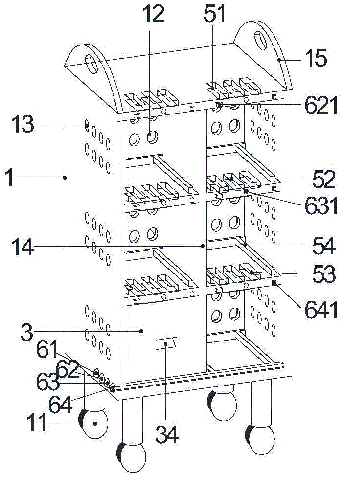
图1为本实用新型一种抽屉式鞋柜的结构示意图;Fig. 1 is the structural representation of a kind of drawer type shoe cabinet of the present utility model;
图2为本实用新型一种抽屉式鞋柜的后视图;Fig. 2 is the rear view of a kind of drawer type shoe cabinet of the present utility model;
图3为本实用新型图1中抽屉式可抽拉鞋盒3的结构示意图;Fig. 3 is the structural representation of the drawer-type pull-
附图标记说明:Description of reference numbers:
1-柜体;11-万向轮;12-导气孔;13-排气孔;14-隔板;15-把手;2-换气风扇;3-抽屉式可抽拉鞋盒;31-滑槽;32-磁铁II;33-通孔;34-凹槽把手;4-弹簧; 51-紫外线杀菌灯;52-远红外加热器;53-臭氧发生器;54-滑轨;61-换气风扇总按钮;62-紫外线杀菌灯总按钮;621-紫外线杀菌灯按钮;63-远红外加热器总按钮;631-远红外加热器按钮;64-臭氧发生器总按钮;641-臭氧发生器按钮。1-Cabinet body; 11-Universal wheel; 12-Air guide hole; 13-Exhaust hole; 14-Partition plate; 15-Handle; 2-Ventilation fan; 3-Drawer type pullable shoe box; 31-Slide 32-magnet II; 33-through hole; 34-groove handle; 4-spring; 51-ultraviolet germicidal lamp; 52-far infrared heater; 53-ozone generator; 54-slide rail; 61-ventilation Fan master button; 62-ultraviolet germicidal lamp master button; 621-ultraviolet germicidal lamp button; 63-far-infrared heater master button; 631-far-infrared heater button; 64-ozone generator master button; 641-ozone generator button .
具体实施方式Detailed ways
为了使本实用新型所要解决的技术问题、技术方案及有益效果更加清楚明白,以下结合附图及实施例,对本实用新型进行进一步详细说明。应当理解,此处所描述的具体实施例仅仅用以解释本实用新型,并不用于限定本实用新型。In order to make the technical problems, technical solutions and beneficial effects to be solved by the present utility model clearer, the present utility model will be further described in detail below with reference to the accompanying drawings and embodiments. It should be understood that the specific embodiments described herein are only used to explain the present invention, and are not intended to limit the present invention.
下面结合附图对本实用新型进行详细说明,本实用新型实施例中,一种抽屉式鞋柜,包括柜体1,柜体1下端面四角位置处设置有万向轮11,柜体1左右两侧上端设置有把手15,柜体1后侧面外壁上可拆卸连接有过滤网,保证鞋柜内的整洁;抽屉式鞋柜还包括刹车装置,刹车装置设置于万向轮11上方及柜体1 下方;通过万向轮11及刹车装置方便控制抽屉式鞋柜的移动和固定。柜体1内通过横隔板分为上腔室和下腔室,在下腔室内设置有控制系统,与下腔室内控制系统相对应的柜体1外侧面上设置有多个总控制按钮,总控制按钮包括换气风扇总按钮61、紫外线杀菌灯总按钮62、远红外加热器总按钮63、臭氧发生器总按钮64,换气风扇总按钮61、紫外线杀菌灯总按钮62、远红外加热器总按钮63、臭氧发生器总按钮64之间并联;通过不同的按钮控制不同的装置运行,避免同时开启整个装置,造成不必要的能耗。The present utility model will be described in detail below with reference to the accompanying drawings. In an embodiment of the present utility model, a drawer-type shoe cabinet includes a
上腔室内通过竖隔板分为前腔室和后腔室,后腔室内设置有换气风扇2,换气风扇2可转动的安装在后腔室内;柜体1后侧面板及竖隔板上开设有相互对应的导气孔12,换气风扇2将外部空气通过导气孔12吹入抽屉式鞋柜内部,且柜体1左右两侧面设置有排气孔13,用以将鞋柜内部的气体排出,实现气体的交换,保证鞋柜内部的通风;前腔室内部通过隔板14被分为多个鞋盒架,各鞋盒架内设置有相适配的抽屉式可抽拉鞋盒3,抽屉式可抽拉鞋盒3正面设置有凹槽把手34,抽屉式可抽拉鞋盒3两侧面设置有与排气孔13相对应的通孔33,用以将抽屉式可抽拉鞋盒3内部的气体排出;各鞋盒架内上侧均固定设置有紫外线杀菌灯51、远红外加热器52和臭氧发生器53,换气风扇2、紫外线杀菌灯51、远红外加热器52、臭氧发生器53以及多个总控制按钮均与控制系统电性连接;各鞋盒架上侧与紫外线杀菌灯51、远红外加热器52、臭氧发生器53相对应位置处均设置有紫外线杀菌灯按钮621、远红外加热器按钮631、臭氧发生器按钮641,且各鞋盒架上的紫外线杀菌灯按钮621之间并联,各鞋盒架上的远红外加热器按钮631之间并联,各鞋盒架上的臭氧发生器按钮641之间并联,通过在不同的鞋盒架上分别设置按钮,可以对不同鞋盒进行不同的处理操作,避免对不需要进行干燥或杀菌的鞋盒进行无用的操作。The upper chamber is divided into a front chamber and a rear chamber by a vertical partition, a
鞋盒架内底部设置有滑轨54,抽屉式可抽拉鞋盒3底部设置有与滑轨54相适配的滑槽31,抽屉式可抽拉鞋盒3通过滑轨54与滑槽31的配合可抽拉的设置于鞋盒架内;抽屉式可抽拉鞋盒3与鞋盒架后侧相对应一面通过弹簧4与鞋盒架后侧连接;鞋盒架内后侧还设置有磁铁I,抽屉式可抽拉鞋盒3与鞋盒架后侧相对应一面设置有与磁铁I相吸引的磁铁II32,磁铁II32位于弹簧4的螺旋圈内并连接抽屉式可抽拉鞋盒3;抽屉式可抽拉鞋盒3位于鞋盒架内部时,弹簧4处于正常状态时,且磁铁I与磁铁II32之间相接触吸引。通过弹簧4的弹性作用及磁铁I与磁铁II32之间的相互吸引作用,保证不使用抽屉式可抽拉鞋盒3时,抽屉式可抽拉鞋盒3位于鞋盒架内,保证鞋柜的整洁美观。The inner bottom of the shoe box rack is provided with a
本实用新型使用时,通过刹车装置和万向轮11实现抽屉式鞋柜的固定和转移;需要对鞋柜进行通风处理时,先通过换气风扇总按钮61开启换气风扇2,换气风扇2将外部空气通过导气孔12吹入抽屉式鞋柜内部,且柜体1左右两侧面设置有排气孔13、抽屉式可抽拉鞋盒3两侧面设置有通孔33,用以将鞋柜内部的气体排出,实现气体的交换,保证鞋柜内部的通风;杀菌除臭和干燥处理时,需要先打开紫外线杀菌灯总按钮62、远红外加热器总按钮63、臭氧发生器总按钮64,而后打开需要进行相关处理的抽屉式可抽拉鞋盒3对应的鞋盒架上侧的紫外线杀菌灯按钮621、远红外加热器按钮631、臭氧发生器按钮641,使相应的抽屉式可抽拉鞋盒3对应的鞋盒架内的紫外线杀菌灯51、远红外加热器52、臭氧发生器53开启运行,进行杀菌、干燥及除臭处理。When the utility model is used, the fixing and transfer of the drawer type shoe cabinet is realized through the braking device and the
上面结合附图对本实用新型进行了示例性的描述,但本实用新型的技术范围并不局限于说明书上的内容,必须要根据权利要求范围来确定其技术性范围。The present invention has been exemplarily described above in conjunction with the accompanying drawings, but the technical scope of the present invention is not limited to the content in the description, and its technical scope must be determined according to the scope of the claims.
Claims (9)
Priority Applications (1)
| Application Number | Priority Date | Filing Date | Title |
|---|---|---|---|
| CN202020023031.XU CN211984452U (en) | 2020-01-07 | 2020-01-07 | Drawer type shoe cabinet |
Applications Claiming Priority (1)
| Application Number | Priority Date | Filing Date | Title |
|---|---|---|---|
| CN202020023031.XU CN211984452U (en) | 2020-01-07 | 2020-01-07 | Drawer type shoe cabinet |
Publications (1)
| Publication Number | Publication Date |
|---|---|
| CN211984452U true CN211984452U (en) | 2020-11-24 |
Family
ID=73425206
Family Applications (1)
| Application Number | Title | Priority Date | Filing Date |
|---|---|---|---|
| CN202020023031.XU Active CN211984452U (en) | 2020-01-07 | 2020-01-07 | Drawer type shoe cabinet |
Country Status (1)
| Country | Link |
|---|---|
| CN (1) | CN211984452U (en) |
Cited By (3)
| Publication number | Priority date | Publication date | Assignee | Title |
|---|---|---|---|---|
| CN113232984A (en) * | 2021-05-21 | 2021-08-10 | 冯鹏 | Settlement material management device for construction cost |
| CN114216139A (en) * | 2021-10-25 | 2022-03-22 | 浙江亚厦装饰股份有限公司 | Detachable cooking integrated storage cabinet |
| CN117356836A (en) * | 2023-11-01 | 2024-01-09 | 中国农业科学院哈尔滨兽医研究所(中国动物卫生与流行病学中心哈尔滨分中心) | An integrated shoe-changing cabinet in a clean room with disinfection and drying functions |
-
2020
- 2020-01-07 CN CN202020023031.XU patent/CN211984452U/en active Active
Cited By (3)
| Publication number | Priority date | Publication date | Assignee | Title |
|---|---|---|---|---|
| CN113232984A (en) * | 2021-05-21 | 2021-08-10 | 冯鹏 | Settlement material management device for construction cost |
| CN114216139A (en) * | 2021-10-25 | 2022-03-22 | 浙江亚厦装饰股份有限公司 | Detachable cooking integrated storage cabinet |
| CN117356836A (en) * | 2023-11-01 | 2024-01-09 | 中国农业科学院哈尔滨兽医研究所(中国动物卫生与流行病学中心哈尔滨分中心) | An integrated shoe-changing cabinet in a clean room with disinfection and drying functions |
Similar Documents
| Publication | Publication Date | Title |
|---|---|---|
| KR100899948B1 (en) | Built-in cabinet with sterile deodorizer | |
| CN203860731U (en) | Multifunctional shoe cabinet | |
| CN205493103U (en) | Shoe cabinet for family life | |
| CN201436908U (en) | Combined disinfection shoe cabinet | |
| CN211882860U (en) | Shoe cabinet that intelligence was disinfected, and deodorization is dried | |
| CN105167420A (en) | Shoe cabinet device for blowing deodorization with solar energy | |
| CN211608634U (en) | Sterilizing and deodorizing drying shoe cabinet | |
| CN211533300U (en) | Three-dimensional shoe cabinet of intelligence house | |
| CN205321725U (en) | Multifunctional shoe cabinet | |
| CN215456370U (en) | Shoe cabinet with sterilization function | |
| KR102373174B1 (en) | Sterilizer for shoe closet | |
| CN205040980U (en) | Utilize solar energy deodorant shoe cabinet device of blowing | |
| CN201153724Y (en) | Sterilizing shoes cabinet | |
| CN2539524Y (en) | Electric heating sterilisation health-care disinfection cabinet | |
| CN211510988U (en) | Deodorization intelligent shoe cabinet | |
| CN218219556U (en) | Intelligent sterilizing wardrobe | |
| CN211608636U (en) | A smart shoe cabinet | |
| CN2456541Y (en) | Health shoe cabinet | |
| CN217644802U (en) | Multifunctional table type sterilizing and drying shoe cabinet | |
| CN220157839U (en) | Shoe cabinet | |
| CN222171602U (en) | An intelligent drying and sterilizing shoe cabinet | |
| CN110811167A (en) | A smart cabinet with air circulation structure | |
| CN208590662U (en) | A kind of Household shoe cabinet | |
| CN216166070U (en) | Clothes sterilizing and disinfecting cabinet | |
| CN219396648U (en) | Ventilated shoe cabinet |
Legal Events
| Date | Code | Title | Description |
|---|---|---|---|
| GR01 | Patent grant | ||
| GR01 | Patent grant | ||
| CP03 | Change of name, title or address | ||
| CP03 | Change of name, title or address |
Address after: 214121 Jiangsu Province, Wuxi high wave West Road, No. 1600 Patentee after: Wuxi Vocational and Technical University Country or region after: China Address before: 214121 Jiangsu Province, Wuxi high wave West Road, No. 1600 Patentee before: WUXI INSTITUTE OF TECHNOLOGY Country or region before: China |