CN211977821U - Detection device - Google Patents
Detection device Download PDFInfo
- Publication number
- CN211977821U CN211977821U CN202020430392.6U CN202020430392U CN211977821U CN 211977821 U CN211977821 U CN 211977821U CN 202020430392 U CN202020430392 U CN 202020430392U CN 211977821 U CN211977821 U CN 211977821U
- Authority
- CN
- China
- Prior art keywords
- driving
- driving member
- detection device
- detection
- signal
- Prior art date
- Legal status (The legal status is an assumption and is not a legal conclusion. Google has not performed a legal analysis and makes no representation as to the accuracy of the status listed.)
- Active
Links
Images


Landscapes
- Details Of Measuring And Other Instruments (AREA)
Abstract
本实用新型提供了一种检测设备,包括底座、固设于底座左右两端的第一支架、设于两第一支架的两个移动组件、架设于两移动组件上的第一连接件、两组第一光栅尺、检测平台、第一检测装置和控制装置;两组第一光栅尺用于分别检测两移动组件驱动第一连接件移动的距离,并将该信号反馈至控制装置;控制装置根据该信号控制两移动组件同步驱动;第一检测装置与第一连接件连接,并能随第一连接件在移动组件的带动下移动,并用于检测支撑于检测平台上的待测产品。两个移动组件和第一连接件组成龙门架结构,能够更好更稳定地支撑第一检测装置,避免产生变形和晃动;两个移动组件同步驱动,使第一检测装置的运行更加平稳,提高检测设备的检测精度。
The utility model provides a detection device, which comprises a base, first brackets fixed on the left and right ends of the base, two moving assemblies arranged on the two first brackets, a first connecting piece erected on the two moving assemblies, two sets of A first grating ruler, a detection platform, a first detection device and a control device; the two sets of first grating rulers are used to respectively detect the distance that the two moving components drive the first connecting piece to move, and feed the signal back to the control device; the control device according to The signal controls the synchronous driving of the two moving components; the first detection device is connected with the first connecting piece and can move with the first connecting piece under the driving of the moving component, and is used to detect the product to be tested supported on the testing platform. The two moving components and the first connecting piece form a gantry structure, which can support the first detection device better and more stably, and avoid deformation and shaking; the two moving components are driven synchronously, which makes the operation of the first detection device more stable and improves the performance of the first detection device. The detection accuracy of the detection equipment.
Description
技术领域technical field
本实用新型属于工业检测技术领域,更具体地说,是涉及一种检测设备。The utility model belongs to the technical field of industrial detection, and more particularly relates to a detection device.
背景技术Background technique
目前,随着机械加工精度以及效率的不断提高,对产品的要求也越来越高,不仅需要在机械加工过程中对产品进行尺寸检测保证内部性能,而且需要在加工完成后对产品的外部尺寸进行检测保证外观属性。因此,检测装置的要求也越来越高。At present, with the continuous improvement of machining accuracy and efficiency, the requirements for products are also getting higher and higher. Not only need to carry out dimensional inspection of products during the machining process to ensure the internal performance, but also need to check the external dimensions of the products after the machining is completed. Inspections are performed to ensure appearance properties. Therefore, the requirements for detection devices are also getting higher and higher.
现有检测方式主要有两种,一是人工使用检测装置进行检测,二是将检测装置安装在机械手上进行检测。然而,一些检测装置重量过大,特别是检测大尺寸产品时,不仅难以人工手持使用;而且安装在机械手上时,由于安装处受力大容易导致机械手变形,且检测移动距离长,易于产生晃动,严重影响检测精度。There are mainly two existing detection methods, one is to manually use a detection device for detection, and the other is to install the detection device on a manipulator for detection. However, some detection devices are too heavy, especially when detecting large-sized products, it is not only difficult to use by hand; when installed on the robot, the robot is easily deformed due to the large force at the installation place, and the detection moving distance is long, which is prone to shaking. , which seriously affects the detection accuracy.
发明内容SUMMARY OF THE INVENTION
本实用新型的目的在于提供一种检测设备,以解决现有技术中存在的检测装置过重影响检测精度的技术问题。The purpose of the present invention is to provide a detection device to solve the technical problem in the prior art that the detection device is too heavy and affects the detection accuracy.
为实现上述目的,本实用新型采用的技术方案是:提供一种检测设备,包括框架、第一移动装置、检测平台、第一检测装置和控制装置;In order to achieve the above purpose, the technical solution adopted by the present invention is to provide a detection device, including a frame, a first moving device, a detection platform, a first detection device and a control device;
所述框架包括底座和固设于所述底座左右两端的第一支架;The frame includes a base and first brackets fixed on the left and right ends of the base;
所述第一移动装置包括分别设于两所述第一支架的两个移动组件、架设于两所述移动组件上的第一连接件、以及两组第一光栅尺;所述移动组件用于带动所述第一连接件移动;The first moving device includes two moving assemblies respectively arranged on the two first brackets, a first connecting piece erected on the two moving assemblies, and two sets of first grating rulers; the moving assemblies are used for driving the first connector to move;
所述第一光栅尺与所述移动组件一一对应连接,用于检测对应的所述移动组件驱动所述第一连接件移动的距离,并将该信号反馈至所述控制装置;The first grating scale is connected with the moving assembly in a one-to-one correspondence, and is used to detect the distance that the corresponding moving assembly drives the first connecting piece to move, and feed the signal back to the control device;
所述控制装置用于接收所述第一光栅尺反馈的信号,并根据该信号控制两所述移动组件同步驱动;The control device is used to receive the signal fed back by the first grating ruler, and control the two moving components to drive synchronously according to the signal;
所述检测平台设于所述底座,用于支撑待测产品;The detection platform is arranged on the base to support the product to be tested;
所述第一检测装置与所述第一连接件连接,并能随所述第一连接件移动,并用于检测支撑于所述检测平台上的待测产品。The first detection device is connected with the first connector, can move with the first connector, and is used for detecting the product to be tested supported on the detection platform.
进一步地,所述移动组件包括固设于所述第一支架的升降机构和连接于所述升降机构的第一驱动件;Further, the moving assembly includes a lifting mechanism fixed on the first bracket and a first driving member connected to the lifting mechanism;
所述升降机构用于带动所述第一驱动件升降运动;The lifting mechanism is used to drive the first driving member to move up and down;
所述第一连接件与所述第一驱动件连接,并能在所述第一驱动件的带动下前后移动;The first connecting piece is connected with the first driving piece, and can move back and forth under the driving of the first driving piece;
每组所述第一光栅尺包括与所述第一驱动件连接的光栅尺A和与所述升降机构连接的光栅尺B;Each group of the first grating rulers includes a grating ruler A connected with the first driving member and a grating ruler B connected with the lifting mechanism;
所述光栅尺A用于检测对应的所述第一驱动件驱动所述第一连接件前后移动的距离,并将该信号反馈至所述控制装置;所述控制装置用于接收所述光栅尺A反馈的信号,并根据该信号控制两所述移动组件的所述第一驱动件同步驱动;The grating ruler A is used to detect the distance that the corresponding first driving member drives the first connecting member to move back and forth, and feed the signal back to the control device; the control device is used to receive the grating ruler A feedback signal, and control the first driving member of the two moving assemblies to drive synchronously according to the signal;
所述光栅尺B用于检测对应的所述升降机构驱动所述第一连接件升降的距离,并将该信号反馈至所述控制装置;所述控制装置用于接收所述光栅尺B反馈的信号,并根据该信号控制两所述移动组件的所述升降机构同步驱动。The grating ruler B is used to detect the distance that the corresponding lifting mechanism drives the first connecting piece to rise and fall, and feed the signal back to the control device; the control device is used to receive the feedback from the grating ruler B. signal, and control the lifting mechanism of the two moving assemblies to drive synchronously according to the signal.
进一步地,所述第一连接件包括与所述第一驱动件连接的第二驱动件和连接于所述第二驱动件的第二光栅尺;Further, the first connecting member includes a second driving member connected with the first driving member and a second grating scale connected with the second driving member;
所述第一检测装置与所述第二驱动件连接,并能在所述第二驱动件的带动下左右移动;The first detection device is connected with the second driving member, and can move left and right under the driving of the second driving member;
所述第二光栅尺用于检测所述第二驱动件驱动所述第一检测装置左右移动的距离,并将该信号反馈至所述控制装置;所述控制装置用于接收所述第二光栅尺反馈的信号,并根据该信号控制所述第二驱动件对所述第一检测装置的驱动。The second grating scale is used to detect the distance that the second driving member drives the first detection device to move left and right, and feed the signal back to the control device; the control device is used to receive the second grating The feedback signal of the ruler is controlled, and the driving of the first detection device by the second driving member is controlled according to the signal.
进一步地,所述第一移动装置还包括连接于所述第二驱动件的第一转动件;所述第一转动件能在所述第二驱动件的带动下左右移动;Further, the first moving device further includes a first rotating member connected to the second driving member; the first rotating member can move left and right under the driving of the second driving member;
所述第一检测装置与所述第一转动件连接,并能在所述第一转动件的带动下旋转运动。The first detection device is connected with the first rotating member and can rotate under the driving of the first rotating member.
进一步地,所述框架还包括固设于所述底座的后端的第二支架;Further, the frame further includes a second bracket fixed on the rear end of the base;
所述检测设备还包括固设于所述第二支架的第二移动装置和连接于所述第二移动装置的第二检测装置;The detection device further includes a second mobile device fixed on the second bracket and a second detection device connected to the second mobile device;
所述第二检测装置用于检测支撑于所述检测平台上的待测产品,并能在所述第二移动装置的带动下移动。The second detection device is used for detecting the product to be tested supported on the detection platform, and can be moved under the driving of the second moving device.
进一步地,所述第二移动装置包括两个第三驱动件、两个第三光栅尺和第二连接件;Further, the second moving device includes two third driving members, two third grating rulers and a second connecting member;
两所述第三驱动件分别固设于所述第二支架左右两端;The two third driving parts are respectively fixed on the left and right ends of the second bracket;
所述第二连接件架设于两所述第三驱动件上,并能在所述第三驱动件的带动下上下移动;The second connecting piece is erected on the two third driving pieces, and can move up and down under the driving of the third driving pieces;
所述第三光栅尺与所述第三驱动件一一对应连接,用于检测对应的所述第三驱动件驱动所述第二连接件上下移动的距离,并将该信号反馈至所述控制装置;所述控制装置用于接收所述第三光栅尺反馈的信号,并根据该信号控制两所述第三驱动件同步驱动;The third grating scale is connected with the third driving member in one-to-one correspondence, and is used to detect the distance that the corresponding third driving member drives the second connecting member to move up and down, and feedback the signal to the control device; the control device is configured to receive the signal fed back by the third grating scale, and control the two third drive members to drive synchronously according to the signal;
所述第二检测装置与所述第二连接件连接,并能随所述第二连接件移动。The second detection device is connected with the second connecting piece and can move with the second connecting piece.
进一步地,所述第二连接件包括架设于两所述第三驱动件上的第四驱动件和连接于所述第四驱动件的第四光栅尺;Further, the second connecting member includes a fourth driving member mounted on the two third driving members and a fourth grating scale connected to the fourth driving member;
所述第二检测装置与所述第四驱动件连接,并能在所述第四驱动件的带动下左右移动;The second detection device is connected with the fourth driving member, and can move left and right under the driving of the fourth driving member;
所述第四光栅尺用于检测所述第四驱动件驱动所述第二检测装置左右移动的距离,并将该信号反馈至所述控制装置;所述控制装置用于接收所述第四光栅尺反馈的信号,并根据该信号控制所述第四驱动件对所述第二检测装置的驱动。The fourth grating scale is used to detect the distance that the fourth driving member drives the second detection device to move left and right, and feed the signal back to the control device; the control device is used to receive the fourth grating The feedback signal of the ruler is controlled, and the driving of the second detection device by the fourth driving member is controlled according to the signal.
进一步地,所述第二移动装置还包括连接于所述第四驱动件的第二转动件;所述第二转动件能在所述第四驱动件的带动下左右移动;Further, the second moving device further includes a second rotating member connected to the fourth driving member; the second rotating member can move left and right under the driving of the fourth driving member;
所述第二检测装置与所述第二转动件连接,并能在所述第二转动件的带动下旋转运动。The second detection device is connected with the second rotating member and can rotate under the driving of the second rotating member.
进一步地,还包括设于所述底座的第三移动装置;所述检测平台与所述第三移动装置连接,并能在所述第三移动装置的带动下移动。Further, it also includes a third moving device arranged on the base; the detection platform is connected with the third moving device and can move under the driving of the third moving device.
进一步地,所述第三移动装置包括第五驱动件、第五光栅尺、辅助轴、第六驱动件和第六光栅尺;Further, the third moving device includes a fifth driving member, a fifth grating ruler, an auxiliary shaft, a sixth driving member and a sixth grating ruler;
所述第五驱动件和所述辅助轴前后间隔固设于所述底座;The fifth driving member and the auxiliary shaft are fixed on the base at a front and rear interval;
所述第六驱动件架设于所述第五驱动件和所述辅助轴上,并能在所述第五驱动件的带动下左右移动;The sixth driving member is erected on the fifth driving member and the auxiliary shaft, and can move left and right under the driving of the fifth driving member;
所述检测平台与所述第六驱动件连接,并能在所述第六驱动件的带动下前后移动,并能随所述第六驱动件左右移动;The detection platform is connected with the sixth driving member, and can move back and forth under the driving of the sixth driving member, and can move left and right with the sixth driving member;
所述第五光栅尺与所述第五驱动件连接,用于检测所述第五驱动件驱动所述检测平台左右移动的距离,并将该信号反馈至所述控制装置;所述控制装置用于接收所述第五光栅尺反馈的信号,并根据该信号控制所述第五驱动件对所述检测平台的驱动;The fifth grating scale is connected with the fifth driving member, and is used to detect the distance that the fifth driving member drives the detection platform to move left and right, and feedback the signal to the control device; the control device uses receiving the signal fed back by the fifth grating ruler, and controlling the driving of the detection platform by the fifth driving member according to the signal;
所述第六光栅尺与所述第六驱动件连接,用于检测所述第六驱动件驱动所述检测平台前后移动的距离,并将该信号反馈至所述控制装置;所述控制装置用于接收所述第六光栅尺反馈的信号,并根据该信号控制所述第六驱动件对所述检测平台的驱动。The sixth grating scale is connected with the sixth driving member, and is used to detect the distance that the sixth driving member drives the detection platform to move back and forth, and feeds the signal back to the control device; the control device uses receiving the signal fed back by the sixth grating ruler, and controlling the driving of the detection platform by the sixth driving member according to the signal.
本实用新型提供的检测设备的有益效果在于:与现有技术相比,第一移动装置包括两个移动组件和第一连接件,并通过移动组件和第一连接件组成龙门架结构,龙门架结构稳定,强度高,第一检测装置安装于第一连接件上,使第一移动装置能够更好更稳定地支撑第一检测装置,不易受第一检测装置的重载影响产生变形,也能防止第一移动装置带动第一检测装置运动时产生晃动从而影响检测精准性;移动组件设于第一支架上,第一支架对移动组件起到支撑作用,避免移动组件受第一检测装置的重载影响产生变形,也能避免移动组件移动时产生晃动;两个移动组件实现双动力驱动第一连接件,驱动力大,保证第一检测装置的移动动力,同时通过两组第一光栅尺分别检测两移动组件驱动第一连接件移动的距离并反馈至控制装置,控制装置根据该信号控制两移动组件同步驱动第一连接件移动,保证双动力驱动一致性,第一检测装置的运行更加平稳,能够严格控制第一检测装置的移动距离,提高检测设备的检测精度。The beneficial effect of the detection device provided by the present invention is that compared with the prior art, the first moving device includes two moving components and a first connecting piece, and a gantry structure is formed by the moving components and the first connecting piece, and the gantry frame The structure is stable and the strength is high. The first detection device is installed on the first connecting piece, so that the first mobile device can support the first detection device better and more stably, and is not easily deformed by the heavy load of the first detection device, and can also Prevent the first mobile device from shaking when driving the first detection device to move, thereby affecting the detection accuracy; the mobile component is arranged on the first bracket, and the first bracket supports the mobile component to prevent the mobile component from being weighed by the first detection device. The deformation caused by the load effect can also avoid the shaking of the moving component when it moves; the two moving components realize the dual power drive of the first connecting piece, the driving force is large, and the moving power of the first detection device is ensured. Detect the distance that the two moving components drive the first connecting piece to move and feed it back to the control device, and the control device controls the two moving components to synchronously drive the first connecting piece to move according to the signal, so as to ensure the consistency of the dual power drive, and the operation of the first detection device is more stable , the moving distance of the first detection device can be strictly controlled, and the detection accuracy of the detection device can be improved.
附图说明Description of drawings
为了更清楚地说明本实用新型实施例中的技术方案,下面将对实施例或现有技术描述中所需要使用的附图作简单地介绍,显而易见地,下面描述中的附图仅仅是本实用新型的一些实施例,对于本领域普通技术人员来讲,在不付出创造性劳动性的前提下,还可以根据这些附图获得其他的附图。In order to illustrate the technical solutions in the embodiments of the present invention more clearly, the following briefly introduces the accompanying drawings that need to be used in the description of the embodiments or the prior art. Obviously, the drawings in the following description are only for the present utility model. For some novel embodiments, for those of ordinary skill in the art, other drawings can also be obtained according to these drawings without any creative effort.
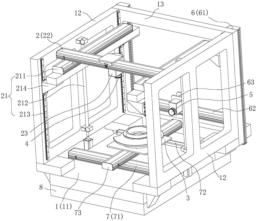
图1为本实用新型实施例提供的检测设备的结构示意图;1 is a schematic structural diagram of a detection device provided by an embodiment of the present invention;
图2为图1中支撑组件的结构示意图;Fig. 2 is the structural schematic diagram of the support assembly in Fig. 1;
图3为图1中第二检测装置和第二移动装置的结构示意图;3 is a schematic structural diagram of a second detection device and a second moving device in FIG. 1;
图4为图1中检测平台和第三移动装置的结构示意图。FIG. 4 is a schematic structural diagram of the detection platform and the third mobile device in FIG. 1 .
其中,图中各附图标记:Among them, each reference sign in the figure:
1、框架;11、底座;12、第一支架;13、第二支架;1. Frame; 11. Base; 12. First bracket; 13. Second bracket;
2、第一移动装置;21、移动组件;211、第一驱动件;212、升降机构;2. The first moving device; 21. The moving assembly; 211, the first driving member; 212, the lifting mechanism;
213、导轨;214、滑动件;213, guide rail; 214, sliding piece;
22、第二驱动件;23、第一转动件;22. The second driving member; 23. The first rotating member;
3、检测平台;4、第一检测装置;5、第二检测装置;3. Testing platform; 4. First testing device; 5. Second testing device;
6、第二移动装置;61、第三驱动件;62、第四驱动件;63、第二转动件;6. The second moving device; 61, the third driving member; 62, the fourth driving member; 63, the second rotating member;
7、第三移动装置;71、第五驱动件;72、辅助轴;73、第六驱动件;7. The third moving device; 71. The fifth driving member; 72. The auxiliary shaft; 73. The sixth driving member;
8、支撑件。8. Supports.
具体实施方式Detailed ways
为了使本实用新型所要解决的技术问题、技术方案及有益效果更加清楚明白,以下结合附图及实施例,对本实用新型进行进一步详细说明。应当理解,此处所描述的具体实施例仅仅用以解释本实用新型,并不用于限定本实用新型。In order to make the technical problems, technical solutions and beneficial effects to be solved by the present utility model clearer, the present utility model will be further described in detail below with reference to the accompanying drawings and embodiments. It should be understood that the specific embodiments described herein are only used to explain the present invention, and are not intended to limit the present invention.
需要说明的是,当元件被称为“固定于”或“设置于”另一个元件,它可以直接在另一个元件上或者间接在该另一个元件上。当一个元件被称为是“连接于”另一个元件,它可以是直接连接到另一个元件或间接连接至该另一个元件上。It should be noted that when an element is referred to as being "fixed to" or "disposed on" another element, it can be directly on the other element or indirectly on the other element. When an element is referred to as being "connected to" another element, it can be directly connected to the other element or indirectly connected to the other element.
需要理解的是,术语“长度”、“宽度”、“上”、“下”、“前”、“后”、“左”、“右”、“竖直”、“水平”、“顶”、“底”“内”、“外”等指示的方位或位置关系为基于附图所示的方位或位置关系,仅是为了便于描述本实用新型和简化描述,而不是指示或暗示所指的装置或元件必须具有特定的方位、以特定的方位构造和操作,因此不能理解为对本实用新型的限制。It is to be understood that the terms "length", "width", "upper", "lower", "front", "rear", "left", "right", "vertical", "horizontal", "top" , "bottom", "inside", "outside", etc. indicate the orientation or positional relationship based on the orientation or positional relationship shown in the accompanying drawings, only for the convenience of describing the present utility model and simplifying the description, rather than indicating or implying that A device or element must have a specific orientation, be constructed and operate in a specific orientation, and therefore should not be construed as a limitation of the present invention.
此外,术语“第一”、“第二”仅用于描述目的,而不能理解为指示或暗示相对重要性或者隐含指明所指示的技术特征的数量。由此,限定有“第一”、“第二”的特征可以明示或者隐含地包括一个或者更多个该特征。在本实用新型的描述中,“多个”的含义是两个或两个以上,除非另有明确具体的限定。In addition, the terms "first" and "second" are only used for descriptive purposes, and should not be construed as indicating or implying relative importance or implying the number of indicated technical features. Thus, a feature defined as "first", "second" may expressly or implicitly include one or more of that feature. In the description of the present invention, "plurality" means two or more, unless otherwise expressly and specifically defined.
请一并参阅图1,现对本实用新型提供的检测设备进行说明。所述检测设备,包括框架1、第一移动装置2、检测平台3、第一检测装置4和控制装置(未在图中示出);Please refer to FIG. 1 together, and now the detection equipment provided by the present invention will be described. The detection device includes a
框架1包括底座11和固设于底座11左右两端的第一支架12;The
第一移动装置2包括分别设于两第一支架12的两个移动组件21、架设于两移动组件21上的第一连接件、以及两组第一光栅尺(未在图中示出);移动组件21用于带动第一连接件移动;The first moving
第一光栅尺与移动组件21一一对应连接,用于检测对应的移动组件21驱动第一连接件移动的距离,并将该信号反馈至控制装置;The first grating scale is connected with the moving
控制装置用于接受第一光栅尺反馈的信号,并根据该信号控制两移动组件21同步驱动;The control device is used to receive the signal fed back by the first grating ruler, and control the two moving
检测平台3设于底座11,用于支撑待测产品;The
第一检测装置4与第一连接件连接,并能随第一连接件移动,并用于检测支撑于检测平台3上的待测产品。The
本实用新型提供的检测设备,与现有技术相比,第一移动装置2包括两个移动组件21和第一连接件,并通过移动组件21和第一连接件组成龙门架结构,龙门架结构稳定,强度高,第一检测装置4安装于第一连接件上,使第一移动装置2能够更好更稳定地支撑第一检测装置4,不易受第一检测装置4的重载影响产生变形,也能防止第一移动装置2带动第一检测装置4运动时产生晃动从而影响检测精准性;移动组件21设于第一支架12上,第一支架12对移动组件21起到支撑作用,避免移动组件21受第一检测装置4的重载影响产生变形,也能避免移动组件21移动时产生晃动;两个移动组件21实现双动力驱动第一连接件,驱动力大,保证第一检测装置4的移动动力,同时通过两组第一光栅尺分别检测两移动组件21驱动第一连接件移动的距离并反馈至控制装置,控制装置根据该信号控制两移动组件21同步驱动第一连接件移动,保证双动力驱动一致性,第一检测装置4的运行更加平稳,能够严格控制第一检测装置4的移动距离,提高检测设备的检测精度。Compared with the prior art, in the detection equipment provided by the present invention, the first moving
优选地,框架1设为大理石框架;大理石支撑稳定性好、硬度高、不易变形,也能避免第一移动装置2移动时影响其他结构的稳定,提高检测精度。Preferably, the
具体地,检测设备还包括支撑件8,底座11固设于支撑件8上;使检测设备的整体安装更加平稳,减缓底座11受到的振动。Specifically, the detection device further includes a
进一步地,请一并参阅图1及图2,作为本实用新型提供的检测设备的一种具体实施方式,移动组件21包括固设于第一支架12的升降机构212和连接于升降机构212的第一驱动件211;Further, please refer to FIG. 1 and FIG. 2 together. As a specific embodiment of the detection device provided by the present invention, the moving
升降机构212用于带动所述第一驱动件211升降运动;The
第一连接件与第一驱动件211连接,并能在第一驱动件211的带动下前后移动;The first connecting piece is connected with the
每组第一光栅尺包括与第一驱动件211连接的光栅尺A和与升降机构连接的光栅尺B;Each group of first grating scales includes grating scale A connected with the first driving
光栅尺A用于检测对应的第一驱动件211驱动第一连接件前后移动的距离,并将该信号反馈至控制装置;控制装置用于接收光栅尺A反馈的信号,并根据该信号控制两移动组件21的第一驱动件211同步驱动;The grating ruler A is used to detect the distance that the corresponding first driving
光栅尺B用于检测对应的升降机构212驱动第一连接件升降的距离,并将该信号反馈至控制装置;控制装置用于接收光栅尺B反馈的信号,并根据该信号控制两移动组件21的升降机构212同步驱动;第一移动装置2能够带动第一检测装置4在前后及上下方向上移动,一次定位产品即能从两个方向检测产品尺寸,减少移动产品积累的测量误差,提高检测精度。The grating ruler B is used to detect the distance that the
具体地,移动组件21还包括分别固设于第一支架12前后两端的两个导轨213、以及滑设于导轨213的滑动件214;Specifically, the moving
第一驱动件211固设于滑动件214;滑动件214与升降机构212连接,并能在升降机构212的带动下升降运动;两个导轨213与滑动件214组成龙门架结构,能够更稳定地支撑第一驱动件211,避免第一驱动件211升降时产生晃动,第一驱动件211的升降更加顺畅,第一检测装置4随第一驱动件211升降更加平稳,提高检测设备的检测精度。The
优选地,第一驱动件211设为直线模组,使第一检测装置4的移动更加稳定,定位精度高,能够更好地控制第一检测装置4的前后移动,提高检测的精准性。Preferably, the first driving
具体地,升降机构212包括滚珠丝杆和连接于滚珠丝杆的第三伺服电机;滚珠丝杆与滑动件214连接,第三伺服电机驱动滚珠丝杆运动,滚珠丝杆带动滑动件214升降运动,从而带动第一检测装置4升降运动;滚珠丝杆传动效率高,摩擦损失小,移动精度高。Specifically, the
进一步地,请参阅图1,作为本实用新型提供的检测设备的一种具体实施方式,第一连接件包括与第一驱动件211连接的第二驱动件22和连接于第二驱动件22的第二光栅尺(未在图中示出);Further, please refer to FIG. 1 , as a specific embodiment of the detection device provided by the present invention, the first connecting member includes a
第一检测装置4与第二驱动件22连接,并能在第二驱动件22的带动下左右移动;The
第二光栅尺用于检测第二驱动件22驱动第一检测装置4左右移动的距离,并将该信号反馈至控制装置;控制装置用于接收第二光栅尺反馈的信号,并根据该信号控制第二驱动件22对第一检测装置4的驱动;第一检测装置4能够在前后、上下及左右方向上移动,增加第一检测装置4的移动方向与范围,一次固定产品即能检测产品的三维尺寸,避免多次移动产品积累测量误差,提高检测精度,控制装置能够根据光栅尺(光栅尺A、光栅尺B或第二光栅尺)的测量信号更精准地控制相应驱动结构(第一驱动件、升降机构或第二驱动件)带动第一检测装置4移动来配合检测,提高第一检测装置4在多方向移动的精度,提高检测设备的灵活性。The second grating scale is used to detect the distance that the second driving
优选地,第二驱动件22设为直线模组,使第一检测装置4的移动更加稳定,定位精度高,能够更好地控制第一检测装置4的左右移动,提高检测的精准性。Preferably, the second driving
进一步地,请参阅图1,作为本实用新型提供的检测设备的一种具体实施方式,第一移动装置2还包括连接于第二驱动件22的第一转动件23;第一转动件23能在第二驱动件22的带动下左右移动;Further, please refer to FIG. 1 , as a specific embodiment of the detection device provided by the present invention, the first moving
第一检测装置4与第一转动件23连接,并能在第一转动件23的带动下旋转运动;增加第一检测装置4的灵活性,检测精准度更高,也便于检测各种产品的外观尺寸。The
具体地,第一转动件23为伺服电机,结构简单,便于安装与控制。Specifically, the first rotating
进一步地,请一并参阅图1及图3,作为本实用新型提供的检测设备的一种具体实施方式,框架1还包括固设于底座11的后端的第二支架13;Further, please refer to FIG. 1 and FIG. 3 together, as a specific embodiment of the detection device provided by the present invention, the
检测设备还包括固设于第二支架13的第二移动装置6和连接于第二移动装置6的第二检测装置5;The detection device further includes a second
第二检测装置5用于检测支撑于检测平台3上的待测产品,并能在第二移动装置6的带动下移动;第二移动装置6设于第二支架13上,第二支架13对第二移动装置6起到支撑作用,使第二移动装置6能够更好更稳定的支撑第二检测装置5,避免第二移动装置6受第二检测装置5的重载影响产生变形,也能避免第二移动装置6移动时产生晃动;提高第二移动装置6移动的稳定性;第二移动装置6能够从另一方位检测产品的尺寸,避免产品超出第一检测装置4的检测范围时需要重新调整产品的位置,提高检测效率和检测精度。The
进一步地,请参阅图3,作为本实用新型提供的检测设备的一种具体实施方式,第二移动装置6包括两个第三驱动件61、两个第三光栅尺(未在图中示出)和第二连接件;Further, please refer to FIG. 3, as a specific embodiment of the detection device provided by the present invention, the second moving
两第三驱动件61分别固设于第二支架13左右两端;The two
第二连接件架设于两第三驱动件61上,并能在第三驱动件61的带动下上下移动;The second connecting member is mounted on the two
第三光栅尺与第三驱动件61一一对应连接,用于检测对应的第三驱动件61驱动第二连接件上下移动的距离,并将该信号反馈至控制装置;控制装置用于接收第三光栅尺反馈的信号,并根据该信号控制两第三驱动件61同步驱动;The third grating scale is connected to the third driving
第二检测装置5与第二连接件连接,并能随第二连接件移动。两个第三驱动件61和第二连接件组成龙门架结构,结构稳定,强度高,第二检测装置5安装与第二连接件上,使第二移动装置6能够更好更稳定地支撑第二检测装置5,不易受第二检测装置5的重载影响产生变形,也能防止第二移动装置6移动时产生晃动从而影响检测精准性;两个第三驱动件61实现双动力驱动第二连接件,驱动力大,保证第二检测装置5的移动动力;同时通过两第三光栅尺分别检测两第三驱动件61驱动第二连接件上下移动的距离并反馈至控制系统,控制系统根据该信号控制两第三驱动件61同步驱动第二连接件移动,保证双动力驱动一致性,第二检测装置5的运行更加稳定,能够严格控制第二检测装置5的移动距离,提高检测设备的检测精度。The
具体地,第三驱动件61设为直线模组,使第二检测装置5的移动更加稳定,定位精度高,能够更好地控制第二检测装置5的上下移动,提高检测的精准性。Specifically, the third driving
进一步地,请参阅图3,作为本实用新型提供的检测设备的一种具体实施方式,第二连接件包括架设于两第三驱动件61上的第四驱动件62和连接于第四驱动件62的第四光栅尺(未在图中示出);Further, please refer to FIG. 3 , as a specific embodiment of the detection device provided by the present invention, the second connecting member includes a fourth driving
第二检测装置5与第四驱动件62连接,并能在第四驱动件62的带动下左右移动;The
第四光栅尺用于检测第四驱动件62驱动第二检测装置5左右移动的距离,并将该信号反馈至控制装置;控制装置用于接收第四光栅尺反馈的信号,并根据该信号控制第四驱动件62对第二检测装置5的驱动;第二检测装置5能够在上下及左右方向上移动,增加第二检测装置5的检测范围,减少移动产品积累的测量误差,提高检测效率与检测精度。The fourth grating scale is used to detect the distance that the fourth driving
具体地,第四驱动件62设为直线模组,使第二检测装置5的移动更加稳定,定位精度高,能够更好地控制第二检测装置5的左右移动,提高检测的精准性。Specifically, the fourth driving
进一步地,请参阅图3,作为本实用新型提供的检测设备的一种具体实施方式,第二移动装置6还包括连接于第四驱动件62的第二转动件63;第二转动件63能在第四驱动件62的带动下左右移动;Further, please refer to FIG. 3, as a specific embodiment of the detection device provided by the present invention, the second moving
第二检测装置5与第二转动件63连接,并能在第二转动件63的带动下旋转运动;增加第二检测装置5的灵活性,检测精准度更高,也便于检测各种产品的外观尺寸。The
具体地,第二转动件63为伺服电机,结构简单,便于安装与控制。Specifically, the second rotating
进一步地,请一并参阅图1及图4,作为本实用新型提供的检测设备的一种具体实施方式,还包括设于底座11的第三移动装置7;检测平台3与第三移动装置7连接,并能在第三移动装置7的带动下移动;检测平台3配合第一检测装置4移动,更便于检测产品,提高检测效率,更加适用于大尺寸产品的检测。Further, please refer to FIG. 1 and FIG. 4 together, as a specific embodiment of the detection device provided by the present invention, it also includes a third
进一步地,请参阅图4,作为本实用新型提供的检测设备的一种具体实施方式,第三移动装置7包括第五驱动件71、第五光栅尺(未在图中示出)、辅助轴72、第六驱动件73和第六光栅尺(未在图中示出);Further, please refer to FIG. 4 , as a specific embodiment of the detection device provided by the present invention, the third moving
第五驱动件71和辅助轴72前后间隔固设于底座11;The fifth driving
第六驱动件73架设于第五驱动件71和辅助轴72上,并能在第五驱动件71的带动下左右移动;The sixth driving
检测平台3与第六驱动件73连接,并能在第六驱动件73的带动下前后移动,并能随第六驱动件73左右移动;The
第五光栅尺与第五驱动件71连接,用于检测第五驱动件71驱动检测平台3左右移动的距离,并将该信号反馈至控制装置;控制装置用于接收第五光栅尺反馈的信号,并根据该信号控制第五驱动件71对检测平台3的驱动;The fifth grating scale is connected with the fifth driving
第六光栅尺与第六驱动件73连接,用于检测第六驱动件73驱动检测平台3前后移动的距离,并将该信号反馈至控制装置;控制装置用于接收第六光栅尺反馈的信号,并根据该信号控制第六驱动件73对检测平台3的驱动;检测平台3能够在前后及左右方向上移动,能够更好的配合第一检测装置4和第二检测装置5检测待测产品,提高检测精度,也更适用于检测大尺寸的产品;控制装置能够根据光栅尺(第五光栅尺或第六光栅尺)的测量信号更精准地控制相应驱动件(第五驱动件或第六驱动件)带动检测平台3移动来配合检测,提高检测设备的灵活性。The sixth grating scale is connected with the sixth driving
具体地,第五驱动件71设为直线模组,使检测平台3的移动更加稳定,定位精度高,能够更好地控制检测平台3的左右移动,提高检测的精准性。Specifically, the fifth driving
具体地,第六驱动件73设为直线模组,使检测平台3的移动更加稳定,定位精度高,能够更好地控制检测平台3的前后移动,提高检测的精准性。Specifically, the sixth driving
以上所述仅为本实用新型的较佳实施例而已,并不用以限制本实用新型,凡在本实用新型的精神和原则之内所作的任何修改、等同替换和改进等,均应包含在本实用新型的保护范围之内。The above are only preferred embodiments of the present invention, and are not intended to limit the present invention. Any modifications, equivalent replacements and improvements made within the spirit and principles of the present invention shall be included in the present invention. within the scope of protection of the utility model.
Claims (10)
Priority Applications (1)
| Application Number | Priority Date | Filing Date | Title |
|---|---|---|---|
| CN202020430392.6U CN211977821U (en) | 2020-03-27 | 2020-03-27 | Detection device |
Applications Claiming Priority (1)
| Application Number | Priority Date | Filing Date | Title |
|---|---|---|---|
| CN202020430392.6U CN211977821U (en) | 2020-03-27 | 2020-03-27 | Detection device |
Publications (1)
| Publication Number | Publication Date |
|---|---|
| CN211977821U true CN211977821U (en) | 2020-11-20 |
Family
ID=73381179
Family Applications (1)
| Application Number | Title | Priority Date | Filing Date |
|---|---|---|---|
| CN202020430392.6U Active CN211977821U (en) | 2020-03-27 | 2020-03-27 | Detection device |
Country Status (1)
| Country | Link |
|---|---|
| CN (1) | CN211977821U (en) |
-
2020
- 2020-03-27 CN CN202020430392.6U patent/CN211977821U/en active Active
Similar Documents
| Publication | Publication Date | Title |
|---|---|---|
| CN103353368B (en) | A kind of torque test platform | |
| CN110132307A (en) | A kind of straight line dynamic calibration apparatus | |
| CN203024970U (en) | Rolling linear guide rail pair comprehensive accuracy and performance test device | |
| CN106383007A (en) | Revolving body axial mass center flexible measuring apparatus based on spiral elevators | |
| CN108731617B (en) | Measuring device for polygonal ball seat slender assembly | |
| CN108710033A (en) | A kind of low-cost and high-precision small scanning frame and control method | |
| CN208840899U (en) | A kind of double drive gantry structures | |
| CN112344886B (en) | Geometric error measuring device and method for hollow guide rail of elevator | |
| CN106363296B (en) | Laser scanning inspection and servo-drive system positioning adjustment workbench | |
| CN218781771U (en) | Three-coordinate measuring machine | |
| CN204229843U (en) | A kind of high precision plane positioning system | |
| CN101319876B (en) | Six-axis test bench | |
| CN103217505B (en) | SMT screen plate detection device | |
| CN202171526U (en) | Performance detecting device of static-pressure air floating guide rail | |
| CN109108672A (en) | A kind of double drive gantry structures | |
| CN221404255U (en) | Installation detection device | |
| CN202614739U (en) | Surface mount technology (SMT) screen plate detecting device | |
| CN220051844U (en) | Motion module for accurate operation of Y axis and Z axis | |
| CN210375036U (en) | Large-scale part plane detection device | |
| CN216889396U (en) | Connect material machine with material strutting arrangement | |
| CN102374949A (en) | Load testing machine | |
| CN216846163U (en) | Transmission mechanism for three-coordinate measuring machine | |
| CN209960151U (en) | Rotating mechanism of non-contact testing device | |
| CN223539262U (en) | Inspection Functional Training Device | |
| CN216889405U (en) | Bilateral survey value connects material machine |
Legal Events
| Date | Code | Title | Description |
|---|---|---|---|
| GR01 | Patent grant | ||
| GR01 | Patent grant |